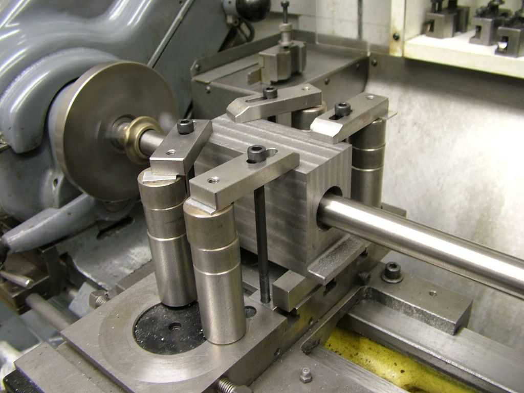
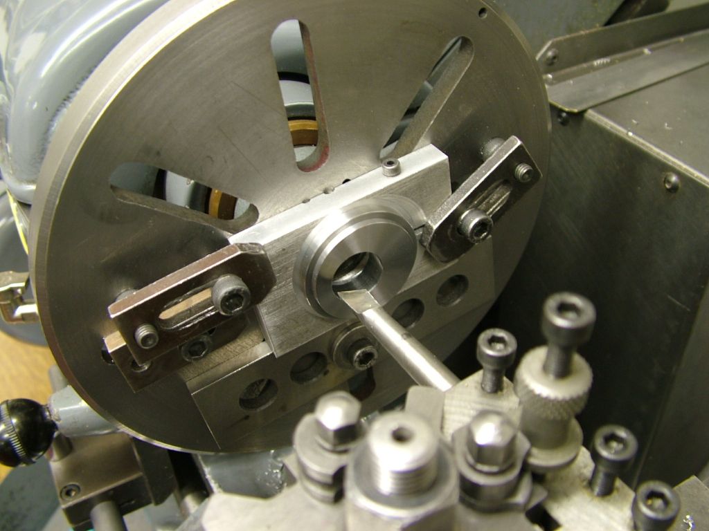
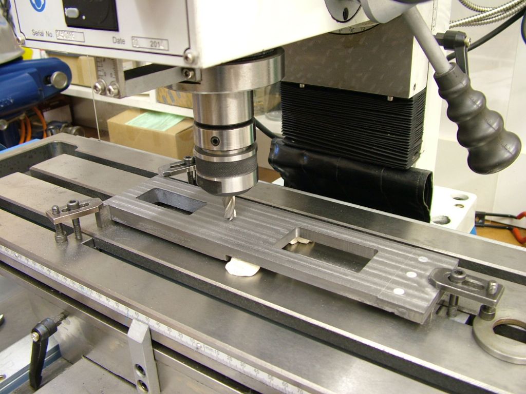
Stuart Twin Victoria (Princess Royal) Mill Engine

Advert

Stuart Twin Victoria (Princess Royal) Mill Engine

Home Forums Work In Progress and completed items Stuart Twin Victoria (Princess Royal) Mill Engine

Viewing 25 posts - 276 through 300 (of 1,206 total)
  • Author
    Posts
  • #555924
    Clive Brown 1
    Participant
      @clivebrown1
      Posted by Dr_GMJN on 27/07/2021 00:21:41:

      ETA I could remove the top clamp for the final fine cuts to eliminate any distortion I guess?

      Edited By Dr_GMJN on 27/07/2021 00:31:44

      I think that's the last thing I'd want to do. Distortion of the CI casting will be insignificant and there's a chance of the set-up moving slightly.

      Clive

      Advert
      #555925
      Zan
      Participant
        @zan

        How about a short turned plug in the feet, then clamp each down with a long stud stud, clamp bar sat on packing

        then add additional clamp bars to the same stud but longer bars going outside the lower clamps, so you now have 8 clamps using 4 studs There would be room in the centre for a strap clamp as well

        it has the additional benefit of making the clamp positions wider on the casting thus removing the tendency of twisting

        with regards to the feet fixings, I think it’s a mistake to tap the holes in the base. The wood plug cantering is very inaccurate and could easily be 10 thou out at each end, thus the bore is angled relative to your base fixings. The easy way is to spot through accurate fitting using plugs in the finished cylinder with reamed holes and a straight bit of silver steel as a pointer. Set this up on the bed, clamp in exact position then tap the base holes. You may find that to correctly align the cylinder ot will need some small rotation so the feet holes will need to be pulled over to allow this . I hope not

        Edit…..perhaps you should rely on the position of the feet holes as you seem to have positioned these very accurately setting these parallel to the lathe axis, then just centering at the headstock end  

        Edited By Zan on 27/07/2021 09:04:08

        Edited By Zan on 27/07/2021 09:08:09

        #555926
        Zan
        Participant
          @zan

          The problem with a strap clamp like yours is that all the down force could be on a single pimple point on the valve face, thus you only have in effect one clamping point with a very high force on it.  This makes them a bit of a problem compared to 4 clamps . Do be certain to use t bars not t nuts or there is a real risk of breaking the t slot in the cross slide, there wupill be considerable force on them

          Edited By Zan on 27/07/2021 09:14:38

          #555928
          Dr_GMJN
          Participant
            @dr_gmjn
            Posted by Zan on 27/07/2021 09:13:14:

            The problem with a strap clamp like yours is that all the down force could be on a single pimple point on the valve face, thus you only have in effect one clamping point with a very high force on it. This makes them a bit of a problem compared to 4 clamps . Do be certain to use t bars not t nuts or there is a real risk of breaking the t slot in the cross slide, there wupill be considerable force on them

            Edited By Zan on 27/07/2021 09:14:38

            Thanks Zan, what's a T-Bar?

            #555933
            Zan
            Participant
              @zan

              Ah. Your beginner status shows again, but Iv been following your posts and your level of skill is impressive!

              t bar, a very long t nut with tapped holes for the studs. Mine for the S7 are 4,2 and 1 inch long with holes tapped every .5” or so they spread the load and minimise the risk of damage. Also be careful the x slide is not bent when the clamps are tightened too much. I’ll provide a sketch of the clamping outlined above if you didn’t fully get it

              #555943
              JasonB
              Moderator
                @jasonb

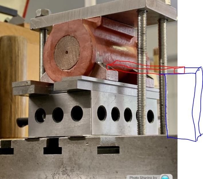
                I'm not sure why you are saying there are not enough tee slots. You could use the slots that the existing top clamp is held down by and easily fit 4 individual clamps with narrowed ends onto each foot pocket and support the other end with blocks.

                vic clamping.jpg


                The machining plate that the casting could be screwed down onto is another method I use quite often usually to hold the whole base of an open crank engine with as the sides of the plate also act as a good straight surface to clock with a DTI


                On the other hand I would say many of these 2 x 1 Stuart cylinders have been machined with just a simple top clamp over the top as that is how Andrew Smith shows them being done in his books and the way I did my beam engine many moons ago and the bar was only 1/4" x 3/4" with a M6 stud either side. Even Tubal Cain uses little more than that in teh Princess Royal article, looks like a bit os 1 x 1 x 1/8" angle to mesmiley


                Edited By JasonB on 27/07/2021 10:17:44

                #555948
                JasonB
                Moderator
                  @jasonb

                  Just had a rumage and found the clamping bar used on my Beam cylinder, probably did not have the othet holes at the time. This clamped the casting to a small faceplate so minimal clamp contact and a smaller "flat" face as I used the port face against the angle plate rather than your wider spread feet. All spinning on the faceplate. This is as I said how Andrew Smith shows it in all his books and I was using his beam engine book as my guide at the time as have many others.

                  20210727_102515[1].jpg

                  #555963
                  Dr_GMJN
                  Participant
                    @dr_gmjn

                    Thanks both. Jason – the other side of the part to your sketch has virtually no room to put a clamp support. It’s the t-slot, a bit of land then fresh air. I can’t move it further over the other way because there are no t-slots where the top slide locates in its hole.

                    I take the point about potentially having a single small contact area on the (unmachined) valve face, but even so, the clamp load has to react somewhere, so this can only be through the machined feet, onto the parallels. BTW I did put a piece of thick paper on the valve face to give a bit more grip.

                    As Jason says, I think the way I’ve done it is similar to what I’ve seen before for this type of thing, but it does seem like it could do with a belt and braces approach.

                    Cheers.

                    #555964
                    Dr_GMJN
                    Participant
                      @dr_gmjn

                      Also – I had to shim and pack to get the right height, and this gives lots of interfaces, all with the potential to slip. I might re-visit the vertical slide method to get around this, but that was also problematic in terms of clamp space when I tried it the other day.

                      #555966
                      Dr_GMJN
                      Participant
                        @dr_gmjn
                        Posted by Zan on 27/07/2021 09:43:17:

                        Ah. Your beginner status shows again, but Iv been following your posts and your level of skill is impressive!

                        t bar, a very long t nut with tapped holes for the studs. Mine for the S7 are 4,2 and 1 inch long with holes tapped every .5” or so they spread the load and minimise the risk of damage. Also be careful the x slide is not bent when the clamps are tightened too much. I’ll provide a sketch of the clamping outlined above if you didn’t fully get it

                        Thanks Zan – yes I understand. I get the basics, and am happy to take time to get things right, but sometimes something just seems a bit wrong and advice is very welcome.

                        #555975
                        JasonB
                        Moderator
                          @jasonb

                          I'd say you still have plenty of room at the back for the packing that the clamp bears on, only needs to be 1/4" wide which will easily keep the stud on the work side of the clamp.

                          Regarding the possible slippyness of the stack of packers, it looks like you are 3/8" plus some feeler gauges. If you have a bit of the 1" x 1/2" aluminium left over from the base take a 2" length, saw it down the middle and then mill to the thickness of what all your packers measure and use one each end of the 1-2-3 block

                          #555982
                          Ramon Wilson
                          Participant
                            @ramonwilson3

                            Been out this morning Doc so only just caught up.

                            Theres nothing wrong in using a bridge clamp per se but in your set up it is the only means of holding. As you say it's on top of a make up of parallels and shims all of which provide a potential for movement. As each bolt is tensioned the forces obviously do transmit downwards through that packing but for maximum effect each would need to be equal relevant to the top surface condition. It will not take much force to bend that plate however slightly and move the pressure point to the edges. A single clamp will press through a single area to ensure a similar clamping force and an even spread of pressure to the four feet

                            Secondary clamping will ensure the component does not move under cutting forces unless the component is restrained by a solid surface – which yours isn't.

                            There may be times when a bridge clamp can be used successfully but usually on a face plate/angle plate set up where the faceplate acts as that restaining surface.

                            As always you pays yer money, The one thing I had instilled in my early machining career is that 'there are no shortcuts'

                            I can well empathise with the desire to get on with the task in hand – let's face it, that's the object of the matter but in my book your set up has a potential for disaster – is it worth that risk – not something at your stage that some extra thinking and a bit more work isn't worth doing.

                            I have nothing more than 6mm bolts and tee nuts and small clamps. They have done me well over many years without the need for the much larger readilly available commercial types which are far too large for small set ups.

                            Might it be worth making a few small clamps before moving on – you certainly have the space between the existing four bolts to add another bolt between with a single clamp and some packing on each side.

                            Like I said, spilt milk, once out of the bottle, isn't going to make a decent cup of teawink Much better to take a step back and move forwards than have to take a step back in order to move forwards.

                            All in your best interests I assure you

                            Regards – Ramon

                            #555992
                            JasonB
                            Moderator
                              @jasonb

                              I don't have a Myford but am fairly sure the tee slots on the vertical slide are at the same spacing as the lathe's cross slide so you could clamp along these lines but two clamps at the back an dtwo at the front so you are clamping on all 4 feet.

                              20210727_132542[1].jpg

                              I've also added the bits of aluminium to replace the stack of packers, though thinking about it would probably have them on top of the 1-2-3 block then the "casting" has something soft to sit down onto

                              20210727_132600[1].jpg

                              #555999
                              Ramon Wilson
                              Participant
                                @ramonwilson3

                                Yes – would agree with that Jason – much more secure.

                                I also prefer to use a vertical slide in situations like this though have used the saddle as Doc is doing but the vertical slide enables precise location in both planes yes Depends on whether you have one of course

                                #556060
                                ChrisH
                                Participant
                                  @chrish

                                  I am following this with interest as one can always learn, esp from set-ups, and I need all the learning I can get!

                                  But I have to say I don’t like the look of your set up at present Doc, doesn’t look right to me and as they say, if it doesn’t look right…………

                                  i would agree and go along with what both Jason and Ramon are proposing – they both speak with so much experience, or, as you have suggested, bolt the feet to a plate and then bolt the plate down.

                                  Bon Chance, as they say just across the Channel

                                  Chris

                                  #556071
                                  Ramon Wilson
                                  Participant
                                    @ramonwilson3

                                    I've been try to find an image of a set up used but this is the only one I have similar to yours Doc

                                    corliss project (20).jpg

                                    The bolts as said are M6 and the clamps are home made from mild steel. They are the largest I possess. The packing is differing lengths of 25mm dia BMS drilled through 6.5 and counterbored to take an M6 caphead head diameter so they can be bolted to the table or faceplate etc if desired. The thin packing provides a slight downward angle to the clamp so pressure is always on the work area and not on the edge.

                                    These small clamps are from my very first lathe, a Unimat SL. They see a lot of use in all sorts of set ups, I have just four of them. The tapped holes in either clamp is so that a cap head screw in reverse to the bolt can be used as adjustable packing as here.

                                    corliss project (76).jpg

                                    You do not need big clamps to secure large parts but it's always best to use several strategically placed

                                    corliss project (21).jpg

                                    Only three are being used here because the part is sitting on three points of contact. Always try to have a solid support between the clamp and the table where ever possible. Sometimes that isn't always the case but be aware that even the slightest tension on an unsupported casting can and probably will, lead to distortion however slight.

                                    Bolting the part to a subplate is of course an acceptable solution too but the rigidity of the setup is down to the size of the bolts. There can be quite a bit of force in boring the first cut on a cylinder from 'as cast' especially if going through a hard spot .

                                    Theres nothing to fear about this op – just want to see you do it successfully yes

                                    Regards – Ramon

                                    #556077
                                    Dr_GMJN
                                    Participant
                                      @dr_gmjn

                                      Thanks all – I’m going to have a re-think now for an hour and see what I can do. I’m leaning back towards the vertical slide, to eliminate height packing interfaces.

                                      I might be able to use the vice clamps I made for the mill last year.

                                      I do like the idea of bolting the feet down.

                                      #556095
                                      Dr_GMJN
                                      Participant
                                        @dr_gmjn
                                        Posted by Zan on 27/07/2021 09:03:04:

                                        Edit…..perhaps you should rely on the position of the feet holes as you seem to have positioned these very accurately setting these parallel to the lathe axis, then just centering at the headstock end

                                        Hmmm yes perhaps it was a mistake to tap the bed holes. There is little room for adjustment within the milled pockets, even with clearance holes for the studs, and I’ve now got a disconnect between them and the cylinder axis, which itself needs to be a best fit to the flange O/Ds. So yes, I will put some short bar (or drill shanks) into the holes and check they are aligned (using a dial gauge) with the lathe bed before boring.

                                        The instructions are a bit vague on all this anyway. It just says (after boring and machining the feet/holes) to assemble the pistons/cross heads, align on the bed and pop through to drill and tap “if you’ve not already done so”. It also mentions drilling and tapping the holes much earlier – when modding the beds – with no mention of cylinder lateral angular alignment at all.

                                        This is why I did it as a have done – having a DRO on a mill seemed to make all alignments for the holes very easy, and enabled me to use the beds as a jig for feet fitting, whereas the instructions seem to assume no mill is available, and I doubt DROs were a thing back then (at least for the amateur).

                                        I think the checks I did before bonding the feet are hopefully good enough, although no way will the wooden plug centre marks be within 0.010” – it was estimated by eye with a pointer.

                                        And to Jason’s point: yes, the instructions show nothing but a piece of steel angle as a saddle clamp, with just two studs holding it down. That’s why I thought my initial method with flat steel, paper packing and four studs might be ok. The number of sliding interfaces did always concern me though.

                                        #556106
                                        Ramon Wilson
                                        Participant
                                          @ramonwilson3

                                          Doc,

                                          All I have written above is based on my own experience both at home and at work and is one of caution and definitely not 'you are going about this the wrong way' as such.

                                          Obviously others have used this form of clamping with success but personally I would not go about it as you have it so far. If you feel happy with following the instructions or Jasons and Zan's thoughts then follow that conviction.

                                          I am not saying it will go wrong, only that it might and if it does it's too late.

                                          If you decide to bolt it to a plate and rely on the bolts to take the forces you really still need to clamp the cylinder otherwise all your cutting forces will transmit through the JB weld adhesion and four 10 ba bolts. Much as I advocate JB weld, and, if it has bonded well, it probably will I would not rely on it in this specific situation.

                                          Ramon

                                          #556109
                                          Dr_GMJN
                                          Participant
                                            @dr_gmjn

                                            Ramon, yes I meant also use a finger clamp on the valve plate (or adjacent flats) in conjunction with bolting down.

                                            Cheers.

                                            #556190
                                            Dr_GMJN
                                            Participant
                                              @dr_gmjn

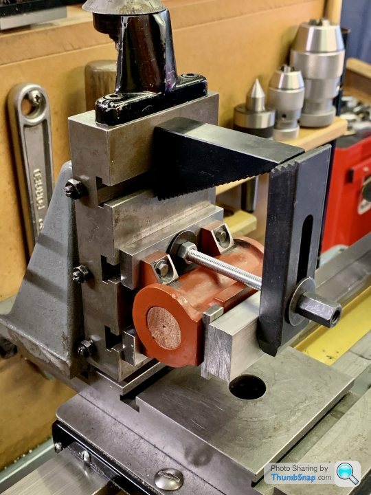
                                              How about this:

                                              Two steel strips drilled and tapped and the feet bolted to them. The strips are then secured to the T-slots (2 bolts in the bottom strip, one in the top strip:

                                              The upper fixing has the threaded bar extended up to form a clamp for the top surfaces, spaced with steel strips and an aluminium spreader:

                                              I guess I could swap the materials of the aluminium spreader and steel spacers.

                                              #556198
                                              JasonB
                                              Moderator
                                                @jasonb

                                                yes

                                                #556205
                                                Ramon Wilson
                                                Participant
                                                  @ramonwilson3

                                                  Much, much better Doc yes

                                                  I note the slide does not have a lock so once you are happy with the position I'd be inclined to lock it using the centre gib screw before cutting commences

                                                  Good luck

                                                  #556221
                                                  Dr_GMJN
                                                  Participant
                                                    @dr_gmjn

                                                    Thanks both. I was going to tighten all three vertical gib screws just to be sure.

                                                    So the procedure I’m thinking is:

                                                    1) Align the vertical slide longitudinally with the bed using a dti.

                                                    2) Then fit the part and check using a dti that it’s not tilted up or down longitudinally. I’ll do this by resting a parallel on two drill shanks temporarily stuck into the mount holes in the uppermost feet, and measuring along it with the dti. This should get me very close to the machined axis being aligned longitudinally with the bed (I know the holes in the bed are bang on equally spaced about its centreline). OK I should have waited to drill the beds until I could align the cylinders after trial fitting the piston rods etc, but too late now. Lesson learned.

                                                    3) Then align to the centre marks using the vertical slide and cross slides (hoping both marks coincide well enough with the centres). If they’re out laterally (shouldn’t be), then I’ll have to shim the feet.

                                                    4) Lock the vertical and cross-slide gibs.

                                                    Then have a go at a cut.

                                                    #556232
                                                    JasonB
                                                    Moderator
                                                      @jasonb

                                                      I would not shim the feet as you would then have to shim the cylinder when you mount it to the engiene

                                                    Viewing 25 posts - 276 through 300 (of 1,206 total)
                                                    • Please log in to reply to this topic. Registering is free and easy using the links on the menu at the top of this page.

                                                    Advert

                                                    Latest Replies

                                                    Viewing 25 topics - 1 through 25 (of 25 total)
                                                    Viewing 25 topics - 1 through 25 (of 25 total)

                                                    View full reply list.

                                                    Advert

                                                    Newsletter Sign-up