Stuart Twin Victoria (Princess Royal) Mill Engine

Advert

Stuart Twin Victoria (Princess Royal) Mill Engine

Home Forums Work In Progress and completed items Stuart Twin Victoria (Princess Royal) Mill Engine

Viewing 25 posts - 251 through 275 (of 1,206 total)
  • Author
    Posts
  • #551891
    Dr_GMJN
    Participant
      @dr_gmjn

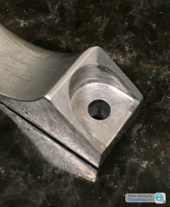
      Foot repair worked fine. Won’t be able to tell when it’s under a coat of paint.

      Advert
      #551916
      Dr_GMJN
      Participant
        @dr_gmjn

        Since there’s now no cladding, I’m wondering if the cylinder end flanges need any work to make them round, so that they match the caps? Nothing mentioned in the articles.

        #551918
        JasonB
        Moderator
          @jasonb

          I found they were quite close. might just want a lick of a file on the underside where the casting line is. Wait until you have the cylinders bored and the covers turned to see what the fit is like.

          cyl flanges.jpg

          #551951
          Dr_GMJN
          Participant
            @dr_gmjn
            Posted by JasonB on 30/06/2021 07:49:56:

            I found they were quite close. might just want a lick of a file on the underside where the casting line is. Wait until you have the cylinders bored and the covers turned to see what the fit is like.

            cyl flanges.jpg

            That looks OK. I think I'll double-check the centre marks I put on the wooden plugs. IIRC two or three are concentric pretty much, but one is a bit off. I assumed the cladding could be made to compensate by filling or whatever.

            I'd rather do this before fitting the feet, because any minor filing would be easier with them out of the way.

            It's a shame the covers protrude above the flats on the cylinder ends; all the ones I've seen assembled are like that. I wonder why they didn't increase the depth of the flats slightly.

            #551965
            JasonB
            Moderator
              @jasonb

              The plugs are usually put in without a ctr dimple and then you mark out the position based on the casting rather than what it looks like you have done which is ctr them first and drive into core. Often cores are out by a lot so should never be trusted as being true.

              Bit more JBW on the flats would sort them out or bond on a bit of ali/brass to bring them up higher.

              #552038
              Dr_GMJN
              Participant
                @dr_gmjn
                Posted by JasonB on 30/06/2021 13:10:06:

                The plugs are usually put in without a ctr dimple and then you mark out the position based on the casting rather than what it looks like you have done which is ctr them first and drive into core. Often cores are out by a lot so should never be trusted as being true.

                Bit more JBW on the flats would sort them out or bond on a bit of ali/brass to bring them up higher.

                Yes, I’ll re-check the plugs, although I think 2 or 3 of them are pretty much spot-on the centre of the arcs I scribed on after with the callipers. Might use aluminium discs instead as I think you also suggested.

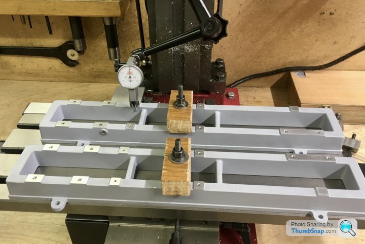
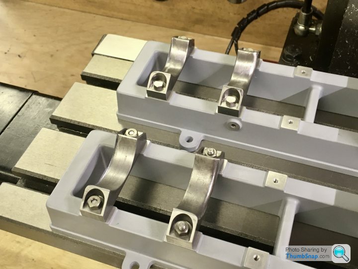
                Set both beds up aligned to the mill base:

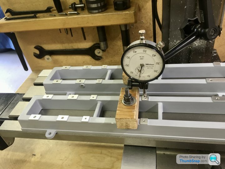
                Checked for height of the pads:

                Then bolted the feet on:

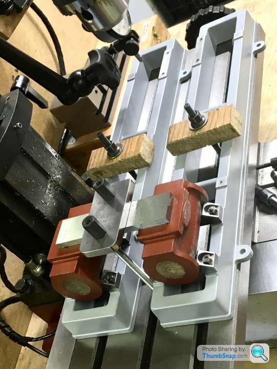
                And placed the cylinders on the feet, with the valve faces clamped nominally flat with a parallel:

                Idea is to use the mill as a primitive CMM, to check the positions of the cylinder centres and valve faces (edges and top faces) before bonding & bolting to the feet.

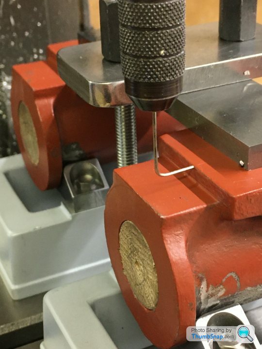
                A quick visual check with a pointer indicated everything was OK. I’ll do some more accurate checks tomorrow on the valve faces, then get the JB Weld out again. I think with the enlarged foot holes and final machining of everything to the finished bores, I’ll have more than enough wiggle room to get everything perfect when it’s eventually assembled (which seems a very long way in the future at the moment).

                #552058
                Ramon Wilson
                Participant
                  @ramonwilson3

                  Looking ood Doc but can I offer a suggestion before it's too late.

                  I have found that it's much better to build the engine up on a solid base board – and preferably the one you intend to display it on from the outset

                  The reason for that is that as you build the engine up any slight misalignments are catered for as you go. When you strip it down for painting there is little to affect it as you rebuild it whereas if it's been built 'off its base' it more than likely will not seat on it's new base with the same freedom. This especially so in your case with two separate engines that need to be in perfect alignment for the best result and particularly where the crankshaft is concerned.

                  Thats based on personal experience with the Waller engine – I built the engine on what I thought was a solid temporary base. When I assembled it after painting on it's proper base I had issues with the crankshaft alignment. Since then I have done as suggested to eliminate that possibility. It certainly paid off with the Corliss engine.

                  Just a thought but one worth considering before you get too far down the road

                  Ramon

                  #552188
                  Dr_GMJN
                  Participant
                    @dr_gmjn

                    Ramon, yes it says something about that in the article, but I assume it’ll apply more to when the crankshaft and flywheel get fitted? I think most of the cylinder/valve gear/sliders etc could be assembled onto the beds before worrying about alignment, or did I miss something? It did mention alignment of the main bearings almost certainly needing shims.

                    Cheers.

                    #552194
                    Ramon Wilson
                    Participant
                      @ramonwilson3

                      Agreed, it won't have too much if any effect on setting the cylinders but the earlier you do it in the process the more secure the foundation upon which the build takes place.

                      Eventually bolting down those beds for instance could induce some deflection that could potentially affect the ease of fit of piston rod/crosshead/crosshead bars. An early sound base will help eliminate such a possibility – if it's going to have to be done anyway why not do it at first and let any influence it might have feature in the build as it progresses.

                      Alignment of the two main shaft bearings is critical to smooth running – to my mind this is definitely one of those times to get the door bolted before the horse takes off.

                      Making sure each stage is running free before moving to the next is my preferred approach so any opportunity to assist that is not overlooked – well not since the Waller engine build

                      Personally I do not subscribe to the oft quoted 'driving' the engine from another source in order to 'run it in' – that is not running in to me but removing tightness and high spots by excess force. Running in should be the bedding in of carefully machined and assembled moving parts – the free movement of which have been created at each stage throughout the build.

                      As always its down to personal choice but the thought is offered with all good intention – certainly not a dictat.

                      Regards – Ramon

                      #552492
                      Dr_GMJN
                      Participant
                        @dr_gmjn

                        Thanks Ramon. My plan is to make the base of plywood, but then apply a scaled parquet effect using lolly sticks. I acquired a load of them recently and – even though it I might not be true to real life – I thought it would look kind of cool, especially if perfectly flatted, stained light oak and given some coats of 2K gloss, then once flatted again, a final coat of 2K satin.

                        Anyway, plenty to do before that. I re-checked the centres of the bores w.r.t the flanges, and I doubt I can get them better as a ‘best fit’. Also checked the valve face edges – again not bad at all. Then degreased the mating faces and on with the JB Weld:

                        Then a final check everything had gone back in place correctly, then clamped down
                        and scraped off all the excess that squeezed out. I’ll leave them now for 48 hours, then drill and tap for the bolts:

                        I keep forgetting I can re-align for best-fit on the faces and feet after boring, but the closer it is now the better I guess.

                        #553993
                        Dr_GMJN
                        Participant
                          @dr_gmjn

                          This is still ‘live’, but it’s taken much longer than anticipated to get my BA fastener order dealt with. Won’t arrive until next week. I thought I’d get everything required in one go, which of course included the screws for the feet-cylinder join.

                          #555267
                          Dr_GMJN
                          Participant
                            @dr_gmjn

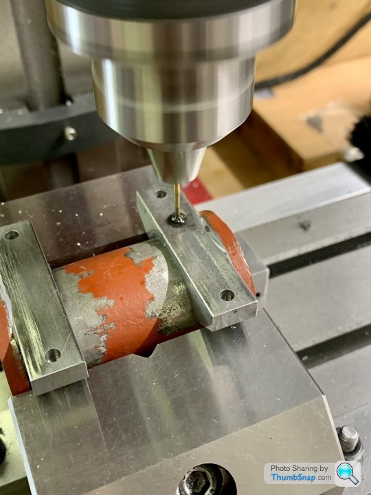
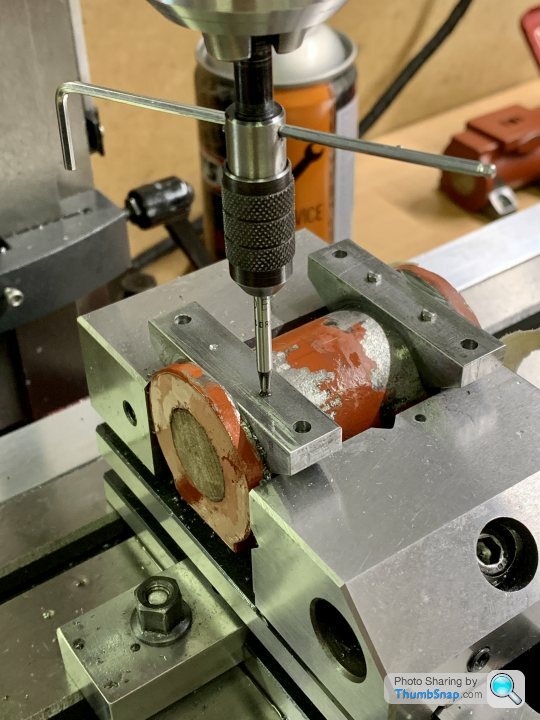
                            The 10BA bolts finally arrived, so I drilled and tapped the cylinder feet to suit:

                            I ground the tip off the tap to ensure the minimum hole depth. Time will tell if the holes will break into the cylinders…

                            They look pretty small for the job, but they are as per the instructions. TBH I think the JB Weld would have been fine on its own.

                            I’ll de-grease everything and fit the bolts permanently after coating with more JB Weld. Then it’s cylinder boring time.

                            #555656
                            Dr_GMJN
                            Participant
                              @dr_gmjn

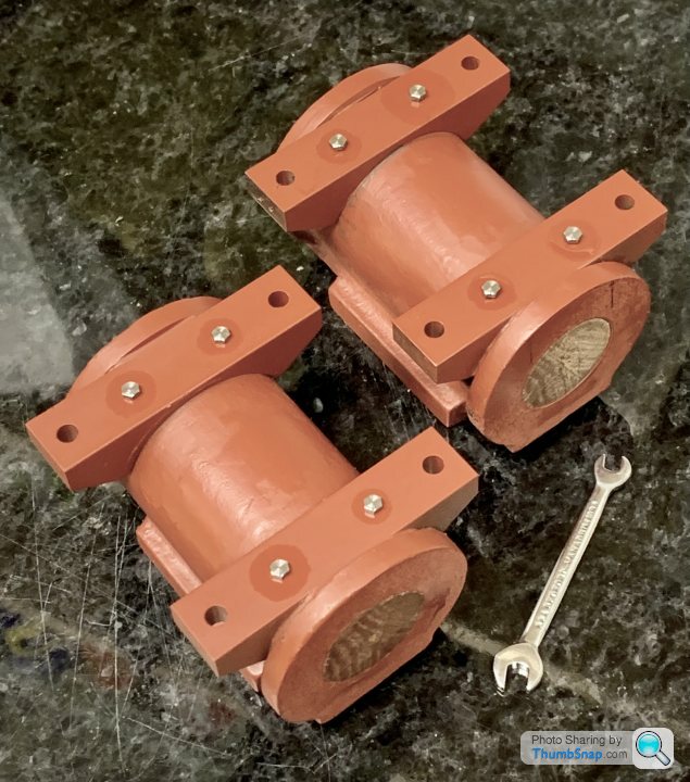
                              JB Welded the screws into the cylinders this afternoon:

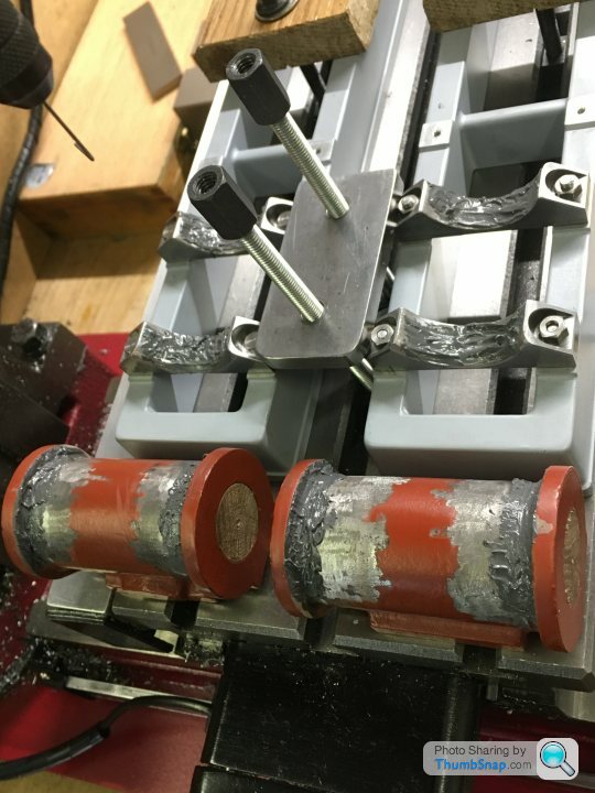
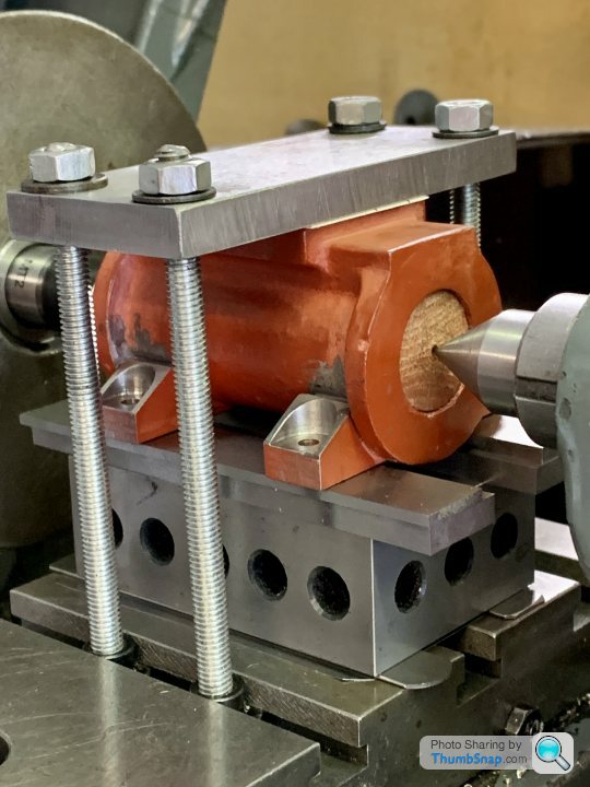
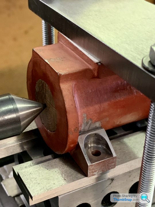
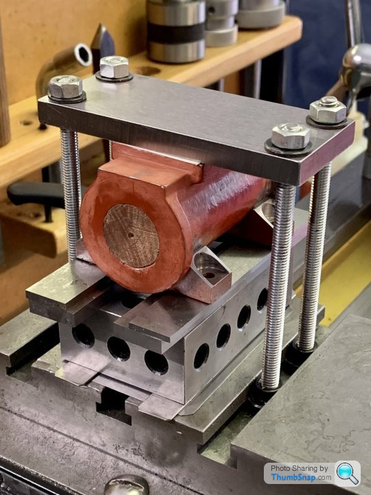
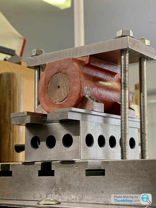
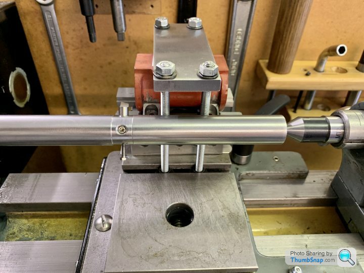
                              And began setting up for boring the cylinders:

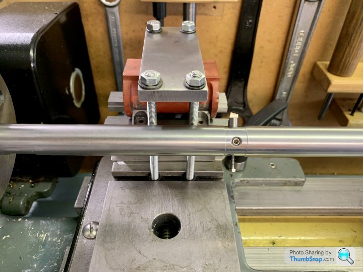
                              And checking the travel – saddle will go left to right:

                              I’ve opted not to fly-cut the cylinder ends – I’ll do all four on a mandrel later on.

                              Can anyone see anything wrong with this, before I remove the centre plugs? I’m a bit concerned about it moving under load. I’ve put some paper under the top plate, but can’t do much with the other interfaces without adjusting the centre height. I suppose I should de-grease all the interfaces? I don’t want to use excessive clamp force in case I distort the bores.

                              Cheers.

                              #555676
                              JasonB
                              Moderator
                                @jasonb

                                Only thing I can see is that you look to have lined things up based on the pop marks in the wooden plugs. Are these true to your feed which have been fitted to the base and 5/8" up from the feet?

                                I also assume you are going to go with Ramon's suggestion of machining the cylinder ends on a mandrel, if not move the packing so you can flycut one end at the same setting as boring and that the piston rod end if facing the headstock.

                                Clamping should be fine.

                                #555679
                                Dr_GMJN
                                Participant
                                  @dr_gmjn
                                  Posted by JasonB on 25/07/2021 18:28:36:

                                  Only thing I can see is that you look to have lined things up based on the pop marks in the wooden plugs. Are these true to your feed which have been fitted to the base and 5/8" up from the feet?

                                  I also assume you are going to go with Ramon's suggestion of machining the cylinder ends on a mandrel, if not move the packing so you can flycut one end at the same setting as boring and that the piston rod end if facing the headstock.

                                  Clamping should be fine.

                                  Thanks Jason. Yes, as I mentioned after the last image, I’m going to machine the ends afterwards, on a mandrel – as per Ramon’s advice.

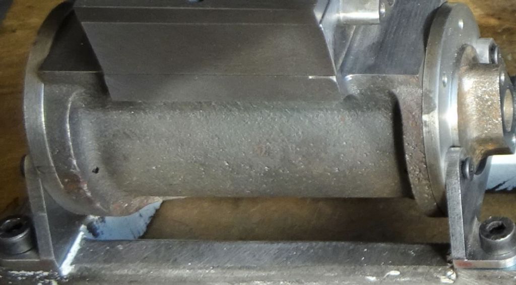
                                  The feet were JB Welded to the cylinders with everything set up on the beds, on the mill. I was able to confirm the centres on the mill after clamping, so I’m confident the feet are very close to height and flat already. This seems to be confirmed by checking the lathe centres align with the plug centres, as per the first two images.

                                  Did you mean true to “feed” or “feet”? You mentioned both.

                                  If anything is out, it can’t be much more than 0.5mm from the marks in the plugs – I can’t detect any centering error visually.

                                  Is there a way of double-checking overall longitudinal alignment? I’ll check the 5/8” height.

                                  Cheers.

                                  #555682
                                  JasonB
                                  Moderator
                                    @jasonb

                                    Feet. You could hold a straight edge against the ends of the feet and move the carriage along while a dti is held against the straight edge.

                                    #555687
                                    Dr_GMJN
                                    Participant
                                      @dr_gmjn
                                      Posted by JasonB on 25/07/2021 19:01:30:

                                      Feet. You could hold a straight edge against the ends of the feet and move the carriage along while a dti is held against the straight edge.

                                      OK I’ll try that too.

                                      The height from the shimmed flats (where the feet sit) to centre height is 3/4”. :

                                      That’s also what it says on the drawing – unless I’ve misunderstood it, in which case I’m in real trouble now…

                                      I’d assumed the 5/8” stepped seat faces of the feet to bore centre would be machined from the finished bore centreline as the datum (using the mandrel) – like the ends? I thought that was the previous advice to machine as much as possible from the finished axis?

                                      #555688
                                      JasonB
                                      Moderator
                                        @jasonb

                                        Forgot you had not cut the notches

                                        #555689
                                        Dr_GMJN
                                        Participant
                                          @dr_gmjn
                                          Posted by JasonB on 25/07/2021 19:24:33:

                                          Forgot you had not cut the notches

                                          No not yet.

                                          #555722
                                          Ramon Wilson
                                          Participant
                                            @ramonwilson3

                                            Hi Doc, can't quite understand why you've drilled and tapped for the 10 ba screws after the feet were JB'd in place?

                                            Set up for boring looks fine but I share your concern of it moving under load. I would if possible re think that clamping as it's never a good idea to rely on a single clamp.The action of tightening those bolts as you have it will tend to bend the clamp plate across the cylinder

                                            You could consider making that top clamp a single one from one side and put two others on the feet on the other side. A thin slip of paper under those feet both sides will improve matters considerably. You have a lot of sliding surface potential so you need to be as sure as you can be before cutting commences as your first cut needs to get under the skin and as such will need to be a decent one.

                                            Not popping in as much as I was due to C/L distraction but good to see progressyes

                                            Hope that boring goes well.

                                            Regards – Ramon

                                            Edited By Ramon Wilson on 26/07/2021 00:08:13

                                            #555741
                                            Dr_GMJN
                                            Participant
                                              @dr_gmjn

                                              Thanks Ramon, I’ll see if I can fit more clamps, or re-arrange, but there’s not much room there.

                                              I assume the bolts are there as a mechanical backup if the Araldite (JB Weld) cracks? Therefore the order they are fitted isn’t that important. It says in the original instructions to clamp the feet to the cylinder, then drill, unclamp, then apply Araldite and final assemble. All I’ve done is added the JB Weld at the clamp stage. I figured that there would also be no gaps at the interface that could have made drilling a bit tricky, and that JB Weld would be way stronger than Araldite.

                                              #555890
                                              Ramon Wilson
                                              Participant
                                                @ramonwilson3

                                                Hello Doc,

                                                It's always best if a clamp can apply a single downwards pressure on a solid spot beneath rather than as you have it. One – it will be much firmer as it applies pressure to something solid and two – it wont tend to distort the casting – not so much an issue with a sturdy cast iron casting but especially important if it's gunmetal or aluminum. Several small clamps are always much more secure than one large one. Sometimes theres no choice but to use an unsupported surface as you have but there should always be reinforcements if possible.

                                                My very first lesson on a one clamp set up, a Stuart Turner hand pump casting left the faceplate/angle plate set up as soon as the tool touched on. And when I say left – it went over my shoulder like a rocket narrowly missing my ear and the corner of the base actually embedding its self in the door surround. Yep – really!

                                                If the JB 'cracks' or parts something would be seriously wrong with it! The bolts could have been there in the first instance to help locate the feet while the JB cured but will have little structural effect if fitted after curing takes place. Still they are there now and won't do any harm.

                                                I try to use the JB as a structural 'part' of the finished item as opposed to using it purely as an 'adhesive' – a heavy chamfer around both curved edges of the cut outs would have allowed the JB to form an internal fillet as well as an external one with a much stronger end result for little extra effort.

                                                Regards – Ramon

                                                #555902
                                                Dr_GMJN
                                                Participant
                                                  @dr_gmjn

                                                  Thanks Ramon. TBH I’m struggling to find room to add clamps to the feet; the nut pockets are quite narrow. I’m thinking of drilling and tapping a steel plate to suit the feet, and screwing the feet directly to it. Then somehow clamp the place down. I’d still keep the top clamp.

                                                  The feet were bolted to their beds while the JB Weld set, and I checked the cylinder alignment once they were in place and clamped (using a pointer in the mill and the DROs), so alignment was pretty good by default. As suggested, the feet machining, cylinder ends and valve face etc will all be machined on a mandrel, so all critical dimensions should be spot-on to the turned cylinder axis. I double-checked the centre marks on the plugs were a best-fit to the o/d of the flanges (not perfectly concentric, then again they can’t be since the flanges are a bit oval), so I doubt I could do much more to get it right.

                                                  ETA I could remove the top clamp for the final fine cuts to eliminate any distortion I guess?


                                                  Edited By Dr_GMJN on 27/07/2021 00:31:44

                                                  #555920
                                                  Ramon Wilson
                                                  Participant
                                                    @ramonwilson3

                                                    Hi Doc,

                                                    Looking at your set up you could turn four short spacers of identical length to sit in the pockets and bridge them with a bar. A single clamp could then be set between the two existing clamp bolts. The pressure on the top plate could then be eased very slightly. The problem with the top plate as it is is that you have no idea if it is applying equal force across the valve face.

                                                    Having 'bought the tee shirt' on occasion with this kind of set up one is met with two distinct feelings – the first is that gut wrenching one where you think you may have just buggered the job followed immediately with the question to oneself why the hell didn't I put that extra clamp on. Biggest issue is having to reset the job accurately if you've half machined away your references.

                                                    I say this only as a note of caution – every op you do successfully is more to lose if having to restart.

                                                    All the best – Ramon

                                                    #555922
                                                    Dr_GMJN
                                                    Participant
                                                      @dr_gmjn

                                                      Thanks Ramon, I’ll have a look later, but I don’t think I’ve got enough T- slots to add finger clamps to both sides.

                                                    Viewing 25 posts - 251 through 275 (of 1,206 total)
                                                    • Please log in to reply to this topic. Registering is free and easy using the links on the menu at the top of this page.

                                                    Advert

                                                    Latest Replies

                                                    Viewing 25 topics - 1 through 25 (of 25 total)
                                                    Viewing 25 topics - 1 through 25 (of 25 total)

                                                    View full reply list.

                                                    Advert

                                                    Newsletter Sign-up