Stuart Twin Victoria (Princess Royal) Mill Engine

Advert

Stuart Twin Victoria (Princess Royal) Mill Engine

Home Forums Work In Progress and completed items Stuart Twin Victoria (Princess Royal) Mill Engine

Viewing 25 posts - 226 through 250 (of 1,206 total)
  • Author
    Posts
  • #550953
    Dr_GMJN
    Participant
      @dr_gmjn

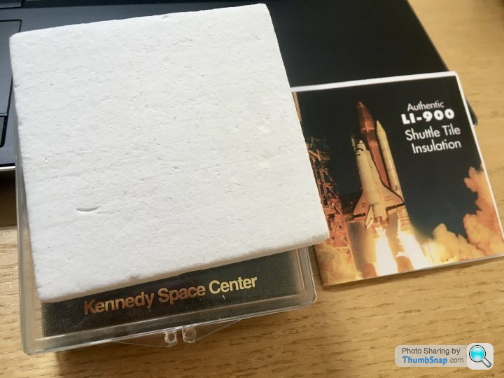
      In fact thinking about it: I’ve got a section of Space Shuttle re-entry tile material somewhere. That should be a good insulator if it’s big enough. I’ll try and find it tomorrow.

      Advert
      #551101
      Dr_GMJN
      Participant
        @dr_gmjn

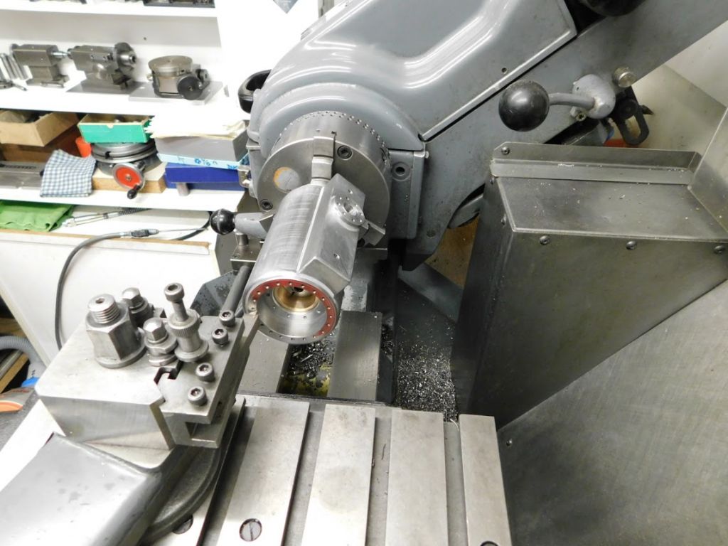
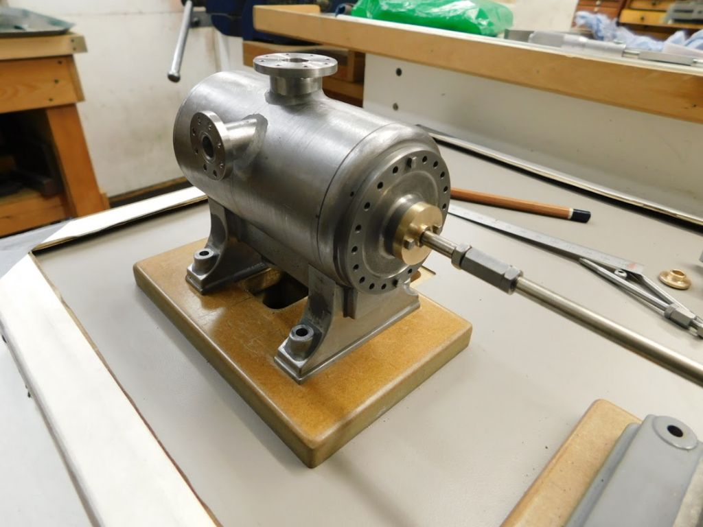
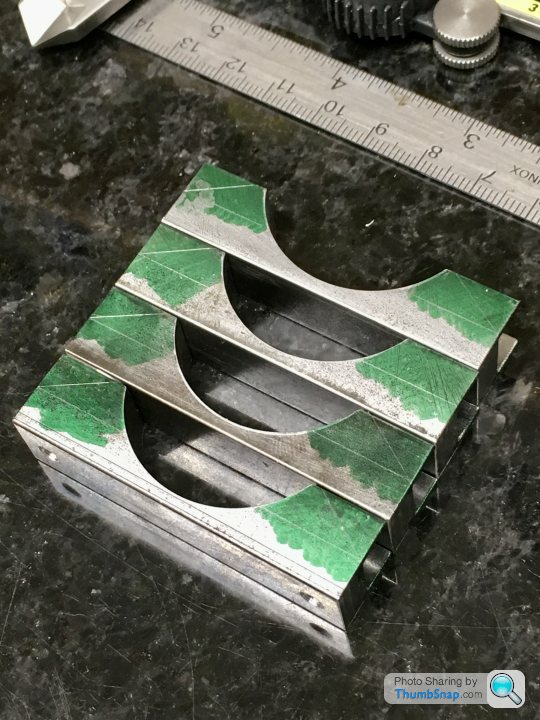
        Soft soldering part 2. As mentioned, I considered using Space Shuttle heat shield insulation to rest the parts on (to retain heat within the parts). I’ve had it for years and it’s pretty useless:

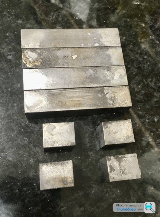
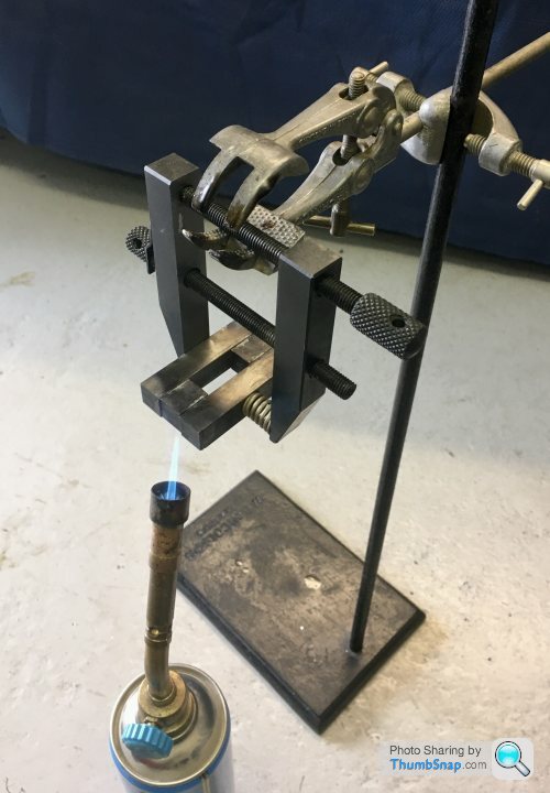
        Then looked at how much it goes for on EBay and thought again (apparently production of it ceased in 1993). Settled on pre-tinning each individual part held in air on a stand:

        Which worked:

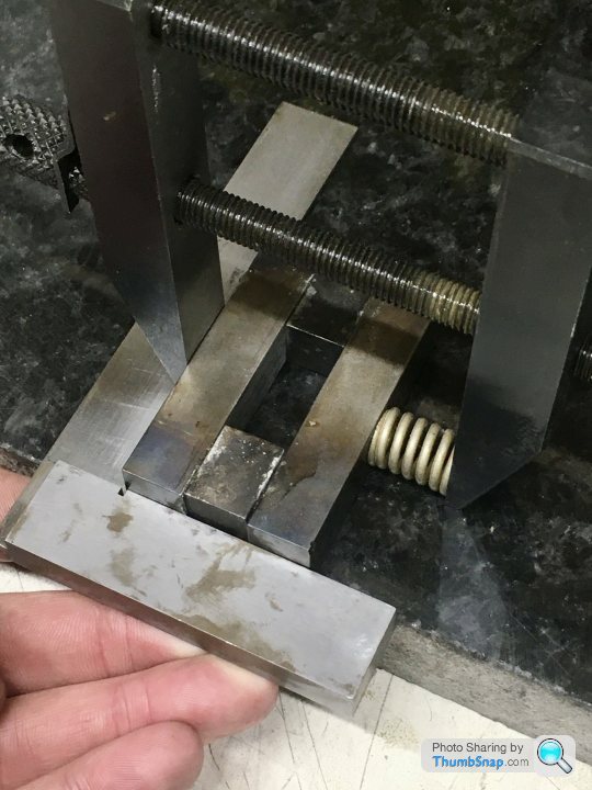
        As per Ramon’s comment, needed to clamp the parts to solder them all together. If a normal clamp was used, when the solder melts, the whole thing would drop out of position. Rather than using piano wire, I spring-loaded a clamp:

        Then hung on the stand and sweated it all together:

        Initially used wood marked with diagonals to get the centre, but checking with dividers gave an offset, which I didn’t want:

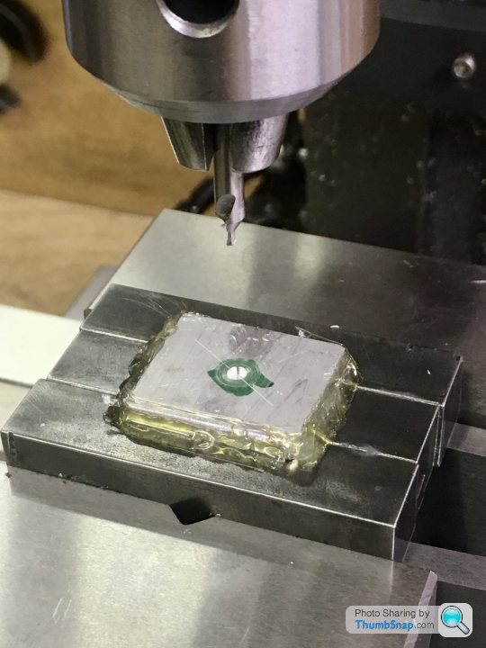
        Remembering Jason’s comment, I used hot melt glue to put a piece of aluminium in the middle, and drilled the centre using the DROs in the mill. Then it was spot-on:

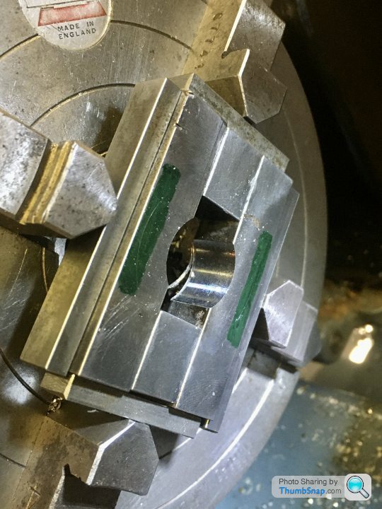
        Then centred in the 4-jaw Chuck using spreader plates:

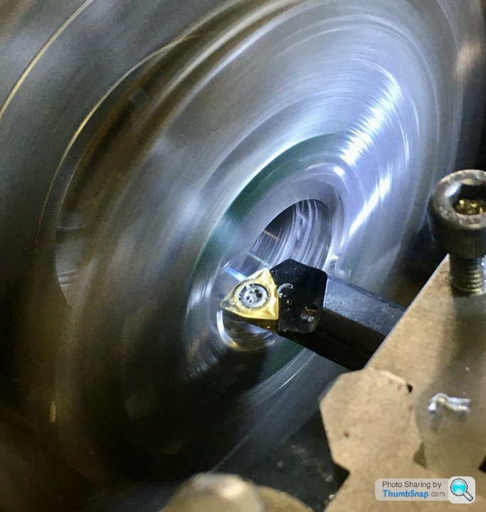
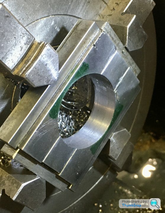
        And gradually opened up to size. The initial cuts were very rough for some reason, almost as if the surface was hardened by the sweating/cooling process. After the third or fourth 0.0025” cut, it became smooth.

        Then un-soldered again:

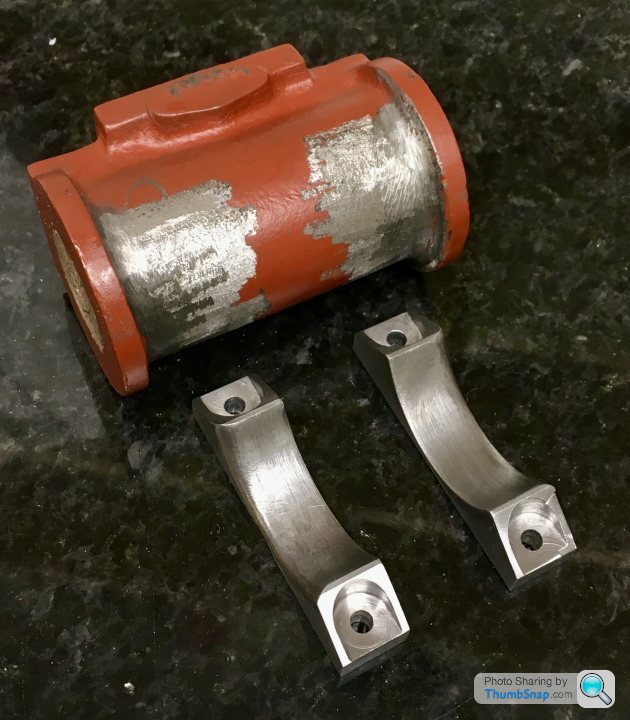
        Seems a good fit for the first one. I suppose I could have turned a chamfer on one side rather than filing it to mate it to the cylinder flanges, but whatever:

        Still quite a bit to do, but so far so good this evening.

        #551109
        JasonB
        Moderator
          @jasonb

          They turned out OK, I suspect the small burner on your torch did not help with the initial soldering problem.

          #551111
          Dr_GMJN
          Participant
            @dr_gmjn
            Posted by JasonB on 24/06/2021 07:07:35:

            They turned out OK, I suspect the small burner on your torch did not help with the initial soldering problem.

            Could be. When I tapped the wooden plug into the centres, one assembly cracked apart – and it wasn’t that tight a fit. Had to re-sweat it.

            Never had an issue with soldering copper plumbing, or electrical stuff, but soldering steel never seems to be very strong the way I do it.

            #551113
            Ramon Wilson
            Participant
              @ramonwilson3

              Nice result Doc yes

              Just a point – do you intend to clean that primer off where the JBW is going ? If not it will only be as good a bond as the primer. Hope that's not teachng granny but worth mentioning just in case.
              Before you JBW them in place file a good, rough, chamfer on the radii – gives an extra surface for the JB to grip onto

              #551114
              Dr_GMJN
              Participant
                @dr_gmjn
                Posted by Ramon Wilson on 24/06/2021 07:58:14:

                Nice result Doc yes

                Just a point – do you intend to clean that primer off where the JBW is going ? If not it will only be as good a bond as the primer. Hope that's not teachng granny but worth mentioning just in case.

                Before you JBW them in place file a good, rough, chamfer on the radii – gives an extra surface for the JB to grip onto

                Thanks Ramon. Intention is to use a sanding cylinder or burr in the dremel to roughen up the mating surfaces on the cylinders and feet.

                #551116
                JasonB
                Moderator
                  @jasonb

                  There is a lot more bulk in those blocks of metal than thin walled copper tube so it will take a lot longer to get the whole of the metal upto temp with that small burner rather than just melting the solder onto the surface.

                  #551206
                  Dr_GMJN
                  Participant
                    @dr_gmjn

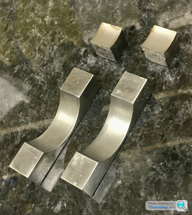
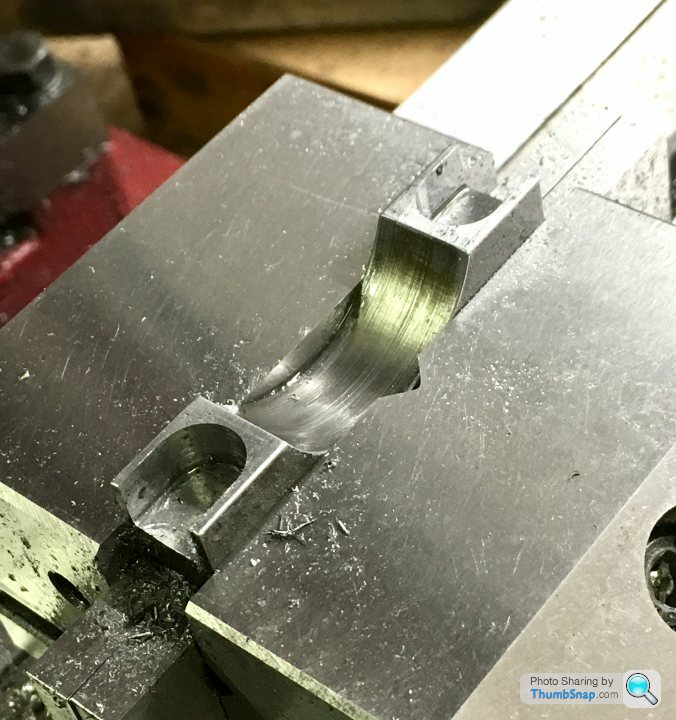
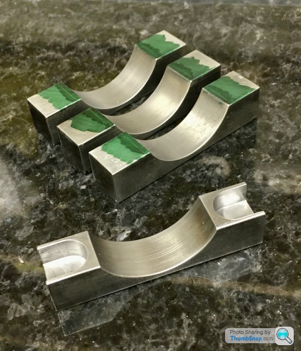
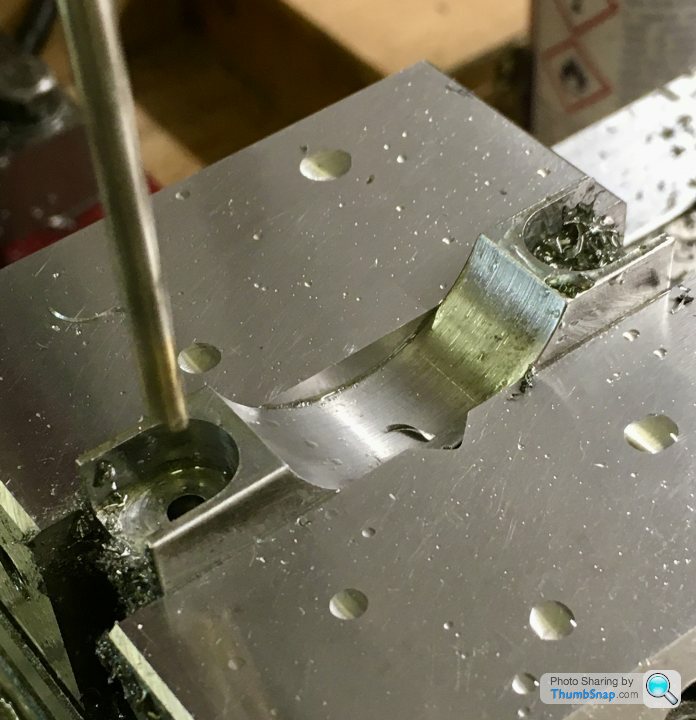
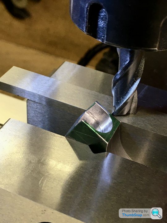
                    Carried on machining the other two feet, which was straightforward, then marked out for the pockets, which I did with a slot drill. I marked the extents of the rads w.r.t. the edges of the arc cut-out:

                    After cutting both pockets I double-checked the centres with the DRO, and they matched the base hole centres, so as per the drawings/instructions:

                    The result (still needs the flanks chamfering):

                    The question is (there’s always a question!):

                    The base holes are spaced at 44.46 mm, the pocket centres in the feet are the same. So, unless the feet are attached to the cylinder castings precisely such that the finished axis ends up dead in the middle (seems unlikely), then the feet hole centres will not match the pocket centres. There will be some lateral mismatch. I checked a 4BA hexagon, and it gives about 2mm gap on radius between the points and the pocket…I can’t bring the pockets any further in toward the castings otherwise they’ll break into the cut-out arc (the edges need still need filing slightly for a snug fit).

                    I think I’ll have to figure out some method of placing the un-bored cylinders onto the properly spaced feet before fixing them (ie using the centred wooden plugs).

                    #551223
                    JasonB
                    Moderator
                      @jasonb

                      Probably overthinking again or maybe underthinking. You need to remember it's a casting you are trying to replicate and that would never have had micron accuracy.

                      #551226
                      Dr_GMJN
                      Participant
                        @dr_gmjn
                        Posted by JasonB on 25/06/2021 07:06:42:

                        Probably overthinking again or maybe underthinking. You need to remember it's a casting you are trying to replicate and that would never have had micron accuracy.

                        Understand the concept of it looking like a casting, just that there’s hardly any wiggle room at all laterally before the bolt/nut points would hit the inside of the pocket’s vertical wall. The longitudinal position of the holes is easy to get perfect simply by making a flat spacer to fit between the foot blocks as a jig.

                        Anyway, it’s probably been done hundreds of times in the past, so there we go. I’d rather ask the question than have to do re-work or make some kind of compromise. Thanks.

                        #551227
                        JasonB
                        Moderator
                          @jasonb

                          You could always put a shallow 1/16" hole in the underside of the cylinder and a matching one in the middle of the feet which would help locate them using a pin when gluing up.

                          #551228
                          Dr_GMJN
                          Participant
                            @dr_gmjn
                            Posted by JasonB on 25/06/2021 08:14:09:

                            You could always put a shallow 1/16" hole in the underside of the cylinder and a matching one in the middle of the feet which would help locate them using a pin when gluing up.

                            I’m ok with the location onto the outside of the cylinder, but the final position of the axis isn’t defined because they’re not bored yet. That’s really the issue, because if they were bored, I could easily line everything up on the mill bed and clamp in place while the JBWeld sets. Then d&t for good measure.

                            basically my assumption is that the bored axis won’t end up being concentric with the outside of the castings, therefore there will be some lateral error. I have no idea how much, but if it’s more than about 1.5 mm it might be an issue in terms of fastener alignment.

                            #551232
                            Ramon Wilson
                            Participant
                              @ramonwilson3

                              Hi Doc, I think you are jumping ahead of the game again by making the feet to finished dimension before you fit them to the cylinder or, to put it another way your cylinder dimensions are now going to be defined by the feet.

                              As Jason rightly says in reality the cast feet would not be symetrical and in all probability, nice as it looks, have neatly milled pockets to surround the nuts. (Think of the type of spanner required if so)

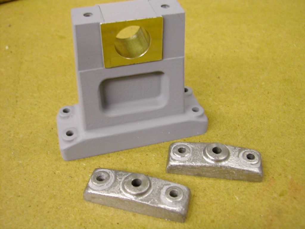
                              Were it me I would mill those feet to finished dimensions – and relative to the finished bore – once securely JB'd in place and also do away with those pockets. A more likely prototypical design would be for the top faces to be slightly tapered downwards in an outwards direction and the nuts seating on inserted but protruding level pads – a little extra work but far more in keeping to a prototype.

                              Something on the lines of this perhaps?

                              0_00000015.jpg

                              Just a thought – hope it helps

                              Ramon

                              #551236
                              Dr_GMJN
                              Participant
                                @dr_gmjn
                                Posted by Ramon Wilson on 25/06/2021 09:25:42:

                                Hi Doc, I think you are jumping ahead of the game again by making the feet to finished dimension before you fit them to the cylinder or, to put it another way your cylinder dimensions are now going to be defined by the feet.

                                As Jason rightly says in reality the cast feet would not be symetrical and in all probability, nice as it looks, have neatly milled pockets to surround the nuts. (Think of the type of spanner required if so)

                                Were it me I would mill those feet to finished dimensions – and relative to the finished bore – once securely JB'd in place and also do away with those pockets. A more likely prototypical design would be for the top faces to be slightly tapered downwards in an outwards direction and the nuts seating on inserted but protruding level pads – a little extra work but far more in keeping to a prototype.

                                Something on the lines of this perhaps?

                                0_00000015.jpg

                                Just a thought – hope it helps

                                Ramon

                                Thanks Ramon. I was really wanting to stick to the original geometry, purely for the sake of proving to myself I can build parts like this from plans and stock material. I don't think the 10V had anything like that.

                                Must admit I'd assumed that by "machining" when in place (i.e. treating as one casting), you guys primarily meant the flats on the base and the fastener holes, rather than the overall form of the feet. I don't think – for the plan parts – that it's possible to machine the pockets and chamfers once assembled to the main casting due to clearance issues. The pocket ends would certainly be extremely close to the cylinder sides, and the cylinder end flanges would obstruct machining of the chamfers.

                                Thinking more about it, I've got the centred plugs in the cylinder bores, and these effectively will be the axes of the finished bores, because they are what I'm aligning the boring bar with. So there must be a way of setting the cylinders on the feet with these as datums while the JB Weld sets. Not quite figured out how yet, but it should easily get me within the necessary tolerance.

                                Cheers.

                                #551252
                                JasonB
                                Moderator
                                  @jasonb

                                  If you mark a ctr line on a flat surface, the feet and then stand them on it with your end to end spacer and hot glue or clamp them in place so ctr lines are lined up you can then apply your JBW and put the cylinder in place then use a square to check your pop marks on the plugs are sitting vertically over the ctr line you should not be far out.

                                  If your nut clearances are as tight as you say then think how you will tighten them, I you stick with that design may need one size smaller hex nuts or hold nut in place and use screws up from the underside through claearence holes if you can't get a spanner in.

                                  Also worth noting that like me ramon tends to run a Dremel over the surfaces to give them a bit of texture and also knock off all the external corners, makes the difference between a painted "barstock" engine and one made from "castings"

                                  #551270
                                  Dr_GMJN
                                  Participant
                                    @dr_gmjn
                                    Posted by JasonB on 25/06/2021 11:36:41:

                                    If you mark a ctr line on a flat surface, the feet and then stand them on it with your end to end spacer and hot glue or clamp them in place so ctr lines are lined up you can then apply your JBW and put the cylinder in place then use a square to check your pop marks on the plugs are sitting vertically over the ctr line you should not be far out.

                                    If your nut clearances are as tight as you say then think how you will tighten them, I you stick with that design may need one size smaller hex nuts or hold nut in place and use screws up from the underside through claearence holes if you can't get a spanner in.

                                    Also worth noting that like me ramon tends to run a Dremel over the surfaces to give them a bit of texture and also knock off all the external corners, makes the difference between a painted "barstock" engine and one made from "castings"

                                    I was thinking put a bit of aluminium plate on the mill bed, co-ordinate d&t four holes to match the bed, then drill the feet blocks close clearance 4BA, at the same time I'm milling the pockets. Might as well mill them to length too. I can also spot two small holes on the plate, and scribe a centreline – as you say.

                                    Then bolt the feet in place and fettle everything so the cylinder seats nicely, and fits laterally using the square to check alignment (within a couple of mm). The height doesn't matter so much because that will be achieved by milling the foot pads later on.

                                    When I'm placing the cylinder, I'll have to check that the valve plate is horizontal, and will clean up once fixed. I suppose I'll have to use the scribing block/surface gauge for this. Might invest in a vernier height gauge at some point, which would probably be easier to set to a precise height for scribing/checking.

                                    So I suppose I'll end up doing half it like a whole casting, and half like an assembly.

                                    BTW a 7/32" socket fits in the pocket, and matches the bolts (which will be nuts on assembly), so tightening shouldn't be an issue.

                                    Thanks.

                                    #551288
                                    Ramon Wilson
                                    Participant
                                      @ramonwilson3

                                      Thanks Ramon. I was really wanting to stick to the original geometry, purely for the sake of proving to myself I can build parts like this from plans and stock material. I don't think the 10V had anything like that.

                                      Fair comment Doc, I was thinking you were going to do a degree of customisation on this build that's all. Just bear in mind that despite a high degree of accuracy in machining individual parts that you don't neccessarily end up with the whole part 'ready to fit'…….


                                      These parts, for the corliss condenser, were, save the base of the feet all pre finished.

                                      throp engine (109).jpg

                                      Despite that, and a high degree of care on assembly there was still the unexpected, and certainly not anticipated, need to do this

                                      throp engine (117).jpg

                                      But, as I'm sure you will do, you get there in the end wink

                                      throp engine (119).jpg

                                      Good luck with it however you go about it yes

                                      Ramon

                                      Edited By Ramon Wilson on 25/06/2021 15:28:04

                                      #551491
                                      Dr_GMJN
                                      Participant
                                        @dr_gmjn

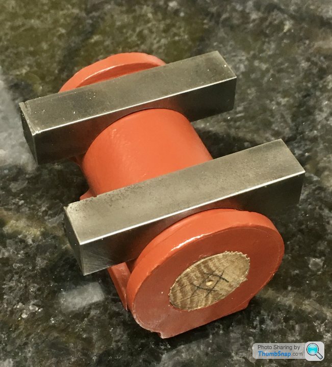
                                        So I machined the slots in the rest of the feet and drilled the mounting holes to be a close fit on the screws. Eventually I’ll open them up to 4mm as per the instructions, to give some wiggle room to adjust on assembly to the beds:

                                        Then, using the holes as datums, trimmed the feet to length, plus a fraction so I can finally machine them once the cylinders are bored:

                                        Then marked out for cutting the chamfers:

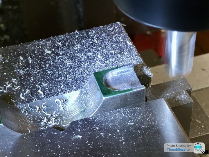
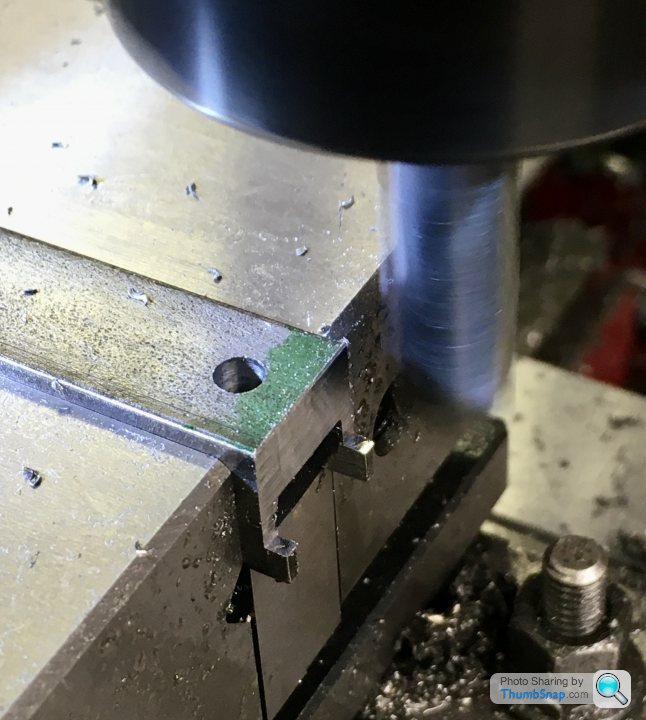
                                        It says in the article to file these, but it was easy enough to do them in the mill…or so I thought.

                                        …but of course, one slight grab with this mill, and all the careful work is undone:

                                        I really need to get a better machine. I know…bad workman and all that, but jeez. Anyway, here they are:

                                        Test fitted:

                                        Then started on grinding and filing a chamfer on one side of each foot, to clear the radius on the cylinders:

                                        And abraded the castings to suit, ready for bonding:

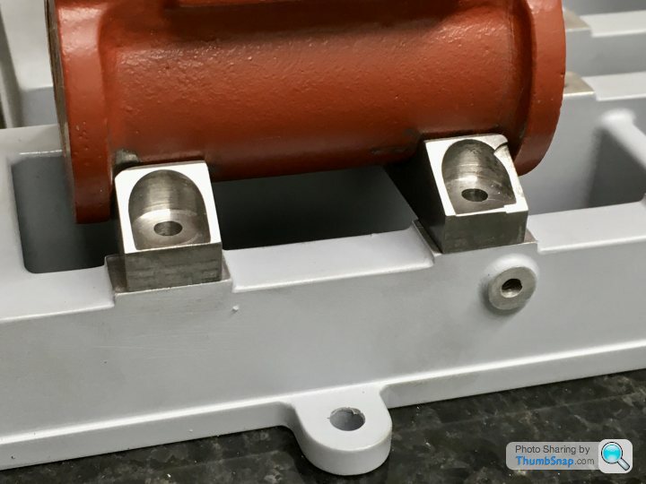
                                        They seem to fit well enough:

                                        A very basic height check seems to indicate all is well there:

                                        So that’s today’s progress:

                                        #551492
                                        Dr_GMJN
                                        Participant
                                          @dr_gmjn

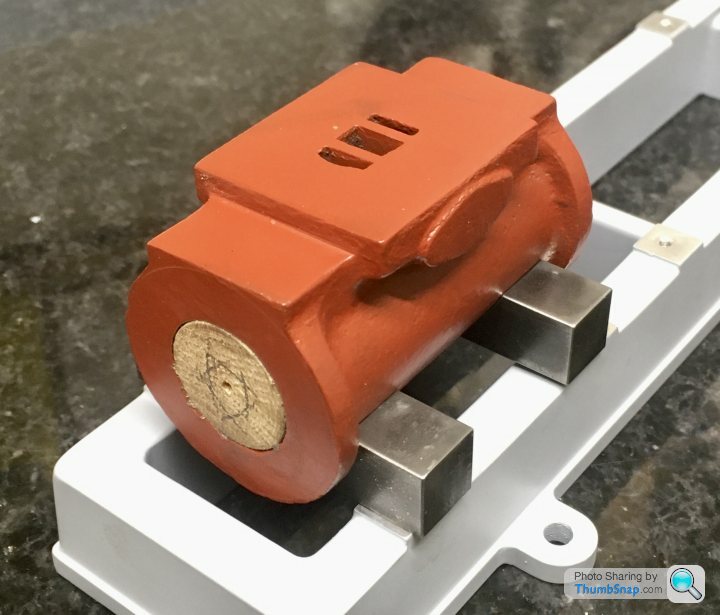
                                          I’ve re-thought the next stage: I’m going to re-fit the bases to the mill bed, align them perfectly, then use them as jigs in conjunction with the DROs and a pointer in the chuck to check the cylinder centre heights, longitudinal alignment and valve face height/level during the JB Welding process. This should get me well within 1mm of alignment once everything is set and bored. Of course final machining of the foot widths, feet pad undersides, valve face and cylinder ends will be done after boring, with the cylinder axis as the datum.

                                          So what to do about the damaged foot? I put JB Weld on a damaged corner of a valve face, and it chipped straight off during filing. Could soft solder a piece on, and re-machine? Could try Milliput? Or buy more steel and start again?

                                          Overall happy so far, considering the stuff I’ve machined is more cosmetic than needing ultimate accuracy…but that mill is driving me mad.

                                          #551494
                                          JasonB
                                          Moderator
                                            @jasonb

                                            If you JBW chipped off that easily either surface was not clean, 2 parts not mixed well enough or not fully set. I usually sticks like S…

                                            #551495
                                            Dr_GMJN
                                            Participant
                                              @dr_gmjn
                                              Posted by JasonB on 26/06/2021 19:23:47:

                                              If you JBW chipped off that easily either surface was not clean, 2 parts not mixed well enough or not fully set. I usually sticks like S…

                                              Thanks – almost certainly the first thing was the issue.

                                              I will clean with thinners, abrade, and then put some on the cut. I’ll use the shank of the slot drill to profile the inside as it sets.

                                              Fingers crossed.

                                              #551497
                                              Dr_GMJN
                                              Participant
                                                @dr_gmjn

                                                Jason – you also mentioned rounding corners to simulate a cast geometry. I’m planning on slightly rounding the outsides of the chamfers, and the end corners of the feet pads.

                                                I will leave the insides of the pockets sharp(ish), because a) it’s difficult to round their edges without them looking sharp/pointed, and b) if they were cast, I’d probably have machined them anyway.

                                                OK on full size, perhaps it would have just been a local spot-face in there, but I’ll call it modeller’s license.

                                                #551526
                                                Dr_GMJN
                                                Participant
                                                  @dr_gmjn

                                                  Briefly going back to the question of cylinder cladding (discussed much earlier in the thread), looking at the feet position w.r.t. the cylinder flanges, I don’t think it’s possible to neatly/realistically clad them at all? Can’t find any examples online. Any comments? I’d rather consider it (ie any further modifications required) now, rather than after the feet are fitted. Thanks.

                                                  #551537
                                                  JasonB
                                                  Moderator
                                                    @jasonb

                                                    May look a bit odd as it will partly cover your "U" shaped pockets, would have been OK with Ramon's simpler foot suggestion.

                                                    #551543
                                                    Dr_GMJN
                                                    Participant
                                                      @dr_gmjn
                                                      Posted by JasonB on 27/06/2021 06:59:39:

                                                      May look a bit odd as it will partly cover your "U" shaped pockets, would have been OK with Ramon's simpler foot suggestion.

                                                      Agreed. I’ll leave the cladding then.

                                                      As mentioned, I really wanted to build this to the M.E. plans, it’s not any particular objection to Ramon’s suggestion. Since starting this project last year, the first thing I now look at when I see a Twin Victoria image, is the cylinder feet (to see if it’s actually a Princess Royal).

                                                      Yes, the bases are very slightly different, but they did give me more to figure out and make than castings.

                                                    Viewing 25 posts - 226 through 250 (of 1,206 total)
                                                    • Please log in to reply to this topic. Registering is free and easy using the links on the menu at the top of this page.

                                                    Advert

                                                    Latest Replies

                                                    Viewing 25 topics - 1 through 25 (of 25 total)
                                                    Viewing 25 topics - 1 through 25 (of 25 total)

                                                    View full reply list.

                                                    Advert

                                                    Newsletter Sign-up