Stuart Turner 7a restoration project

Advert

Stuart Turner 7a restoration project

Home Forums Work In Progress and completed items Stuart Turner 7a restoration project

Viewing 21 posts - 26 through 46 (of 46 total)
  • Author
    Posts
  • #740700
    half whit
    Participant
      @half-whit

      20240710_082634

      Advert
      #740705
      Hopper
      Participant
        @hopper

        Simple but effective!

        Yes, home workshop work seems to be constant compromises with not the right gear or not the right materials available. Innovation is the order of the day.

        Engine is looking good.

        #740722
        half whit
        Participant
          @half-whit

          Hi Hopper,

          Thanks for the reply. I should have added a message with the last photo.

          As you can see I have the eccentric rod inverted on the angle plate, shoulders cut and then drilled and tapped for the bolts. Sacrificial plate in between the angle and the rod.

          Next job is using the slitting saw to part the lower and upper halves.

          Not done it yet as unsure how the loose half will react as the saw completes its cut.

          Will the metal fracture first and then “dance” around. Never used the saw on metal so looking for some help. how will it react or am I worrying over nothing?

          Geoff

          #741770
          half whit
          Participant
            @half-whit

            Hi

            Just been turning up the eccentrics for the reversing gear.

            It was useful having the original eccentric as when mounted on an expanding mandrel I could shift it around in the jaw until the eccentric runs true. This set the machining for the two eccentric blanks. The two will bonded together using a suitable jig to align them correctly. One the the bosses will then be machined away

            #741772
            half whit
            Participant
              @half-whit

              20240716_15224420240717_091102

              #741785
              Hopper
              Participant
                @hopper

                Nice.

                You can hold the offcut bit with a pair of pliers or a bit of wire down one of the screw holes if you are careful to avoid the slitting saw blade.

                #741969
                half whit
                Participant
                  @half-whit

                  Hi Pete,

                  Thanks for the reply.

                  The eccentric rods parted off easily so panic over. I was surprised how resilient the gun metal was right up to point where the slitting saw completed the cut.

                  The two eccentrics are now finished and will need to be bonded together to form the dual eccentric shown in drawing below. I have turned a male and female register on the mating faces to help with alignment on assembly. (Sorry yet more engineering sexism). I would imagine that I will be able to cobble up some sort of jig to align the two parts accurately but any help, from anyone, would be recieved gratefully.

                  So why is the angle 30. Is that characteristic of this engine and how accurate does the setting have to be?

                  20240718_133105

                  #741971
                  Hopper
                  Participant
                    @hopper

                    Valve gear design is a dark art, subject of many books. And reversing gear more so. Probably angle is not critical on a model for display running. Within a few degrees probably ok I should think.

                    #741977
                    JasonB
                    Moderator
                      @jasonb

                      30deg is quite common on small steam engines like this and is what I usually set mine to as a starting point even though I tend to run on air. Angle is not critical I just eyeball the angle of a hex driver in teh grub screw hole.


                      This is from my Fowler drawings, a bit of trig or these days CAD will give you the distance the location block needs to be from the ctr when the eccentrics are at the required angle.

                      valve setting

                      #741987
                      half whit
                      Participant
                        @half-whit

                        Ok sorted, nice one Jason.20240718_153123

                        #748801
                        half whit
                        Participant
                          @half-whit

                          Hi All,

                          Continued slow progress, but with most reverse gear parts now made, a question on timing.

                          20240823_193034

                          I have Andrew Smiths book on making the Stuart 10v, which has a section on making the reversing gear and concludes with timing instructions. I assume these instructions would be the same for my 7a.

                          He uses the inside (straight) eccentric rod for forward rotation of the engine and the outside bent rod for reverse rotation. Setting the valve timing for forward rotation of the engine is much what you would expect and the same as for setting the engine without reversing gear. Now the valve timing for reversing the engine is automatically set when you set the timing for forward rotation as the two eccentrics are linked together, but of course the reverse timing is a “country mile” out from the forward setting. I can’t see how the engine will run smoothly on the reverse setting which tells me I’m setting the engine to run smoothly when going forward but rough in reverse. Is that correct?

                          Geoff

                          #748813
                          SillyOldDuffer
                          Moderator
                            @sillyoldduffer
                            On half whit Said:

                            One of the things I really like about model engineering is looking at a drawing and wondering how on earth I’m going to make that part. Of course it usually requires some detailed thought …


                            Geoff

                            If your interests include 3D-CAD, I often translate 2D-drawings into 3D objects as a way of confirming I’ve understood the 2D plan.

                            Necessary because plans from the Golden Age of Model Engineering are notorious for mistakes, ambiguities and omissions.   The best drawings are very good, but quite a few appear to have been done by amateurs in a hurry and not checked before publication.  A few years ago I found a plan that mixed First and Third Angle projection on the same drawing!  On top of that, there’s no system for correcting poor plans, so mistakes made in 1924 still bite today.

                            Apart from spotting dimensional mistakes, modelling objects in 3D often suggests ways of machining the real part.   And of improving the design!   A CAD package that supports Assemblies will also identify fit problems – two or more parts where the individual 2D drawings look reasonable, but don’t align together in the real world.    Axle bigger than the bearing etc.

                            Dave


                            #748825
                            JasonB
                            Moderator
                              @jasonb

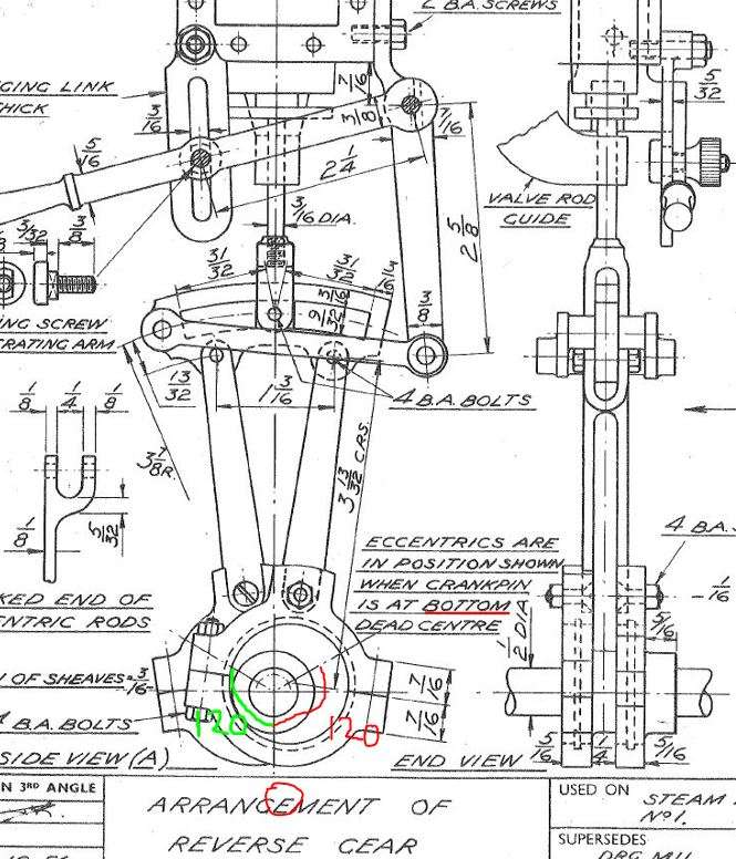
                              The two eccentrics should be sitting equally either side of the crank throw so in fwd that eccentric leads by say 120deg and in rev the other eccentric should be leading the crank by the same 120deg angle.

                              Therefore as the reverser in moved to fwd and reverse the timing should be virtually the same. If you have fixed the eccentrics a bit bias in one direction, have different length oods or the expansion link is not moving fully each way then you will not get it exactly th esame each way. It should not be far off  equal with fwd being set the best position but if it is a long way off something is not right.

                              looking at your photo the outer reverse eccentric looks far to near to the crank pin. The high point should be 90deg plus 30deg lead eg 120 from the pin

                              #748828
                              Phil P
                              Participant
                                @philp

                                Dave

                                I too always model things up in 3D CAD (Solidworks), I found out many years ago that virtually all of the published designs have schoolboy errors in them.
                                So if I work exclusively to my own drawings I have only myself to blame if it goes wrong, thankfully that happens very rarely. It does add a lot of extra time onto a project, but I would rather do that than end up scrapping parts.

                                Phil

                                #748836
                                JA
                                Participant
                                  @ja

                                  It took some time to erect the reversing gear on my Stuart Turner 7A but it is good in both directions. One comment, strictly the gear is not a Stephensons arrangement where the expansion link is pivoted at the centre, not the far end. The modification was made to give a longer drag link. If you are interested there is a very good booklet by Don Ashton on Stephensons and Walschaersts reversing gear.

                                  As Dave (2) says model engineering drawing practice left a lot to be desired as did a lot of general engineering drawings before the war (I have a .jpg of an LMS 0-6-0 cylinder which is truely awful, including confusion over projections). With the introduction of CADs in model engineering things have improved. It is always a good idea to redraw a model, one part at a time using a lot of space. I do my assemblies in 2D, without difficulty, to avoid the complexities of learning solid modeling. (I have learn solid modeling three times in my life and it just takes too much time). Redawing also gives you a better understanding of the model.

                                  JA

                                  Dave

                                  If you want, I can post pictures of reversing gear on my 7A

                                  #748838
                                  JasonB
                                  Moderator
                                    @jasonb

                                    If you tae the Fowler drawing I posted earlier you can see that the two high spots of the eccentrics are 120deg from the crank pin.

                                    120deg

                                    Compare that with your image and although only one eccentric can be seen it’s high spot is maybe only 10 or 20deg from the crank shaft throw.

                                    10deg

                                    No need to draw all the linkage sout in CAD, just sort out the correct position of the eccentrics.

                                    #748842
                                    JasonB
                                    Moderator
                                      @jasonb

                                      Here is an engine that I have added a second eccentric to. Also added two rods into the grub screw holes, the holes are positioned to line up with the highest part of the eccentrics throw as that makes it easy when setting up an engine.

                                      With the crank throw at the top you can see either eccentric throw is 120deg from the crank. Set your eccentrics like that not as you have them. If you can’t then you have got something wrong when machining the pair. I think you may simply have the eccentric 180deg out of position.

                                      ecc setup


                                      #748844
                                      JasonB
                                      Moderator
                                        @jasonb

                                        This is for the No1 just an upsid edown version of what I have shown above

                                        setup 2

                                        #748945
                                        half whit
                                        Participant
                                          @half-whit

                                          Morning All,

                                          Right, I’ve got it, the eureka moment.

                                          The drawing in your previous post Jason, for the No. 1 engine sorted it for me.

                                          I set the eccentrics and rods exactly the same and the valve settings now look almost spot on, in both forward and reverse, just a little fine tuning needed. I now understand the angular setting of the eccentrics, like I say EUREKA. Thanks J.

                                          Thanks to all for the other replies. 3d modelling would certainly been of help even though the solution is really quite simple, but not for me now, Techsoft 2d is my limit.

                                          I found it interesting the comments on errors in old drawings. I bought the reversing gear drawing for this engine and have found one error which led to making the part again. The drawing is dated January 1954. You may think perhaps that should have been corrected by now?

                                          Now let’s see if I can get a test running and post a video

                                          Thanks again Geoff

                                          #764222
                                          half whit
                                          Participant
                                            @half-whit

                                            Hi All,

                                            Well finally all finished and with much the same colour scheme as when purchased at this time last year. I had loads of trouble setting this engine up, mainly because I didn’t research the reversing gear before starting. Having said it now runs really well, so naturally very pleased.

                                            Couple of pictures here

                                            20241113_125940T

                                            #764224
                                            half whit
                                            Participant
                                              @half-whit

                                              I thought I had posted two photos. Here are some more. The plinth has been hollowed out to create a storage area. No prizes for guessing what’s inside?

                                              20241113_13000120241113_130034


                                            Viewing 21 posts - 26 through 46 (of 46 total)
                                            • Please log in to reply to this topic. Registering is free and easy using the links on the menu at the top of this page.

                                            Advert

                                            Latest Replies

                                            Viewing 25 topics - 1 through 25 (of 25 total)
                                            Viewing 25 topics - 1 through 25 (of 25 total)

                                            View full reply list.

                                            Advert

                                            Newsletter Sign-up