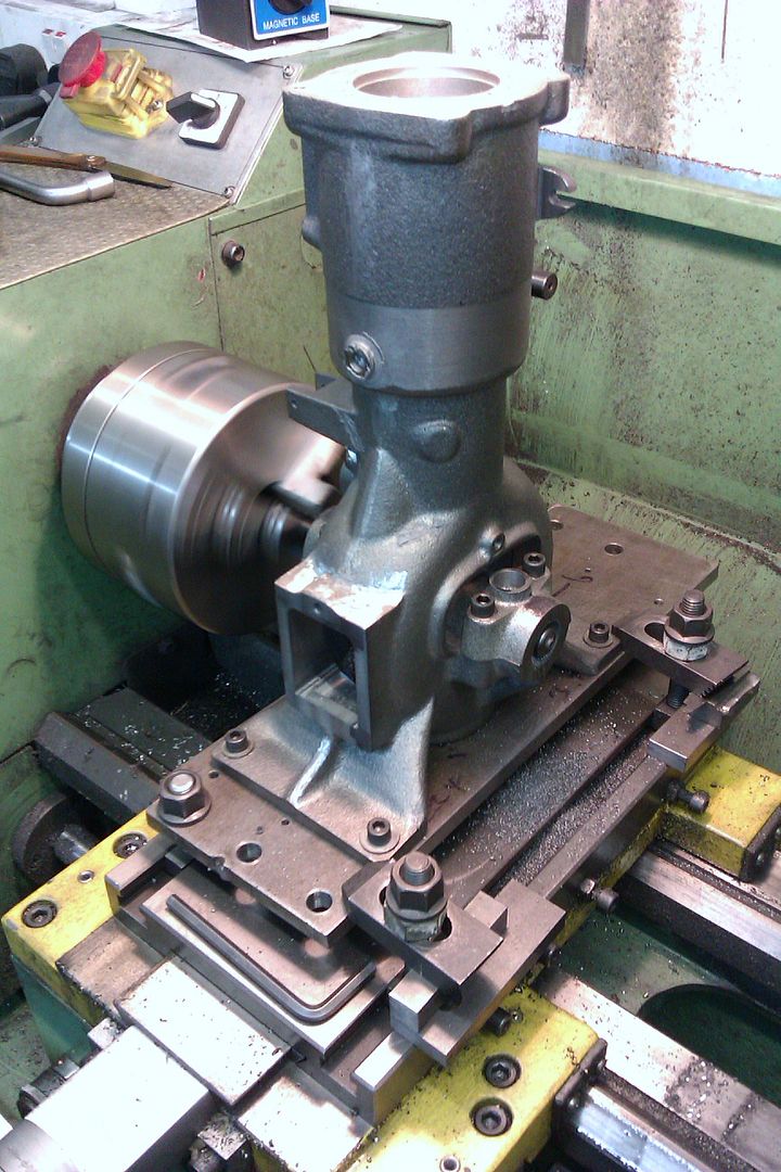
Stuart ‘No.1’ : a beginners tale..

Advert

Stuart ‘No.1’ : a beginners tale..

Home Forums Work In Progress and completed items Stuart ‘No.1’ : a beginners tale..

Viewing 25 posts - 126 through 150 (of 245 total)
  • Author
    Posts
  • #151951
    JasonB
    Moderator
      @jasonb

      Like roy say bolt them bown and bore on teh lathe, if the hole is 8mm at the moment then you will have enough to play with.

      I'm also in agreement with Roy, I tend to do my crankshafts first and then do bearings, flywheels eccentrics etc to fit the crankshaft

      If you are using those boring head type bars make sure there is enough clearance behind the tool. Another way to open them up is with a milling cutter, a 10mm would straighten up the wonky 8mm hole quite well.

      Advert
      #151961
      GarryC
      Participant
        @garryc

        Thanks Jason thats really helpful. Sorry I imagine these are dumb questions but does the following sound an ok way to go about things –

        Drill a small hole in the other (blank, no hole yet) bearing then gradually open out using slot mills(?) to about the same as the other 'bad' bearing – doing this on the mill.

        Then with the engine sole plate on the lathe cross slide use a slot mill to straighten out the 'wonky' first bearing hole – then bore to slightly undersize through both bearings.

        I'm assuming I would slot mills for this rather than end mills?

        Then on to the crankshaft before final boring of the bearings to fit..

        A big thank you.

        Allan.

        #151969
        JasonB
        Moderator
          @jasonb

          Sounds OK but I would get the crank done then you only have to set things up once on the lathe.

          As there is a pilot hole you could use 2, 3 or 4 flute cutters you don't have to use the a centre cutting mill such as a slot drill so you can use what you have to hand rather than go out an buy slot drills.

          #151977
          GarryC
          Participant
            @garryc

            Thats great, thanks Jason. I'll probably get the bearings close first to make sure that all goes ok – but have to set up twice then on the lathe as you say…

            It was while reading about possible problems drilling Gunmetal that I came across some info somewhere suggesting that a mill cutter was less likely to catch / grab at the work than a drill bit due to the side cutters (unless I misunderstood) – but had no idea I could make holes like this… so hence the attraction to try it this way..

            I do have both End and Slot Mills..

            Cheers.

            Allan.

            #151983
            Anonymous

              I regularly use slot drills for 'drilling' brass and bronze above about 10mm diameter. The reason that slot drills are less prone to snatch is most likely because the helix tend to be slower than on jobbers drills, so the cutting edge is less acute. I've got a few small straight flute drills for brass, although they don't seem to be available now. There are however slow spiral drills available specially for brass.

              Andrew

              #151986
              Anonymous

                Allan,

                I must have posted this picture somewhere on the forum already, but here is the current state of the traction engines:

                final drive gears fitted.jpg

                On the downside nothing has been done in the last couple of months, as I am swamped with work.

                Andrew

                #151990
                GarryC
                Participant
                  @garryc

                  Hi Andrew

                  Great photo, must be brilliant to work at that scale… ah one day maybe!

                  and it was interesting to hear that you are using slot drills for brass…

                  Cheers.

                  Allan.

                  #152014
                  GarryC
                  Participant
                    @garryc

                    Todays little bit of progress is to get the 2nd bearing halfs' soldered together, cleaned up enough to get back in the housing to check the fit and get setup on the mill for drilling and milling the hole to 8mm – ready to go onto the lathe..

                    Photo –

                    The setup ready to drill and mill the bearing to 8mm. Not tightened down yet so the table is not left under torque until I can do it…

                    The photo's not very clear but the bearing is in a kind of cradle of parallel's which I hope will help support the solder joint when drilling, and stop things moving around – all really because my current vice not good enough to use for this..

                    and my centre finder to line the mill up..

                    104. setting up to drill the second bearing.jpg

                    Regards

                    Allan.

                    #152052
                    John Olsen
                    Participant
                      @johnolsen79199

                      You have got me trying to remember how I did my two Stuart #1s now. I don't really remember, but I would be very wary about relying on solder joints while machining, even if the chuck is supporting the job together.

                      I can tell you what I did with my Stuart triple. With this one, it is not practical to drill the full length of the bed and line bore. While you can easily make an extended drill when needed, it would be sure to wander. So the bearings are done in a jig. This is a seat for one bearing top and bottom half to fit into, complete with a couple of little studs to clamp them together just as they would be in the finished job. This is set up in the lathe in the four jaw chuck so that the desired bearing centre line is on the centre of the lathe. If the bearings don't already have a hole in them, you can do this with a wobbler. Once it is set up, you can bore all the bearings in turn, two for a #1 and 4 for the triple. The bearing parts should be marked to stay together and also to make sure that they all remain in same relationship. This is so that if there is any error they will all be out in the same direction. Now, since the seats for the bearings in the baseplate should all have been machined at the same setting, when we put the bearings in place they should all line up. This worked well enough for my triple.

                      Assuming the existing pieces were held like this in a jig, it would be no problem to clean out the existing holes with a slot drill. A normal twist drill should not be used, since it will try to align itself to the existing holes halves, which would tend to break the drill or at best make it wander. Once the holes are cleaned up it would be no problem to bore them normally. Although in many cases it is best to make the hole first and then make the thing that goes in it to fit, this is not necessarily the case with crankshafts where it is quite often better to get the crankshaft made with a nice finish first, then make a bearing to fit.

                      So anyway, you don't need to write off those bearings yet.

                      John

                      #152089
                      Anonymous
                        Posted by Allan. on 09/05/2014 22:06:38:

                        Great photo, must be brilliant to work at that scale… ah one day maybe!

                        There are pros and cons. The main con is that everything costs more, the bigger castings are into the hundreds of pounds. A big pro is that I can see what I'm doing; makes a change from the electronics in the day job. Electronic components are getting ever smaller. I got an email flyer the other day for a simple logic IC, if I remember correctly it was 0.8mm square, and they got five connections in that space. No leads of course, they're a bit old fashioned these days. wink 2

                        Andrew

                        #152102
                        GarryC
                        Participant
                          @garryc

                          Hi John

                          That's an interesting post and some really good tips in there, thanks. So far if there's been a choice (and so far I've been lucky that there has been) I've been avoiding making tools and jigs – to be able to put all the time I have directly into working on the engine(s). Time I hope will get easier over the next couple of years as other commitments drop away to then be able to consider such things more….. But I'm taking on board and very grateful for all of the advice I can get for the future…

                          Hi Andrew

                          Yes, it's easy looking in from afar to forget the 'upscale' in expense as well..! I have it in mind though that longterm that is exactly what I'm working towards…

                          I've been having a great and interesting but eventful time drilling / milling the bearings this morning – post up later…

                          Cheers.

                          Allan.

                          Edited By Allan. on 11/05/2014 13:14:43

                          #152121
                          GarryC
                          Participant
                            @garryc

                            My bearings turning into a bit of a saga I think. Hope not everyone has given up on me yet though and some still finding it as interesting as I do…

                            This morning I made a start on the bore for the second bearing, intending to go to 10mm (not 8mm as previously said) ready to go on the lathe… After putting a 10mm Slot mill through the 'bad' bearing to sort out the wonky hole they should then be pretty close for further work..

                            The first slot mill about to be put through – 8mm

                            105. about to put the first slot mill through the second bearing.jpg

                            All going well with the slot mill, nice and smooth, no 'grabbing' of the work then progress stopped. I couldn't understand it for a while – then I realised that the Slot Mill had a 'shoulder' on it and I had reached it's maximum depth. None of my other Slot Mills have a shoulder – just this one! Unlucky again or just stupid for not noticing – don't answer that! Anyway my next Slot Mill size is 10mm (no shoulder) so off I go with that one, and again all going well until i come to the bottom of the hole and about to break through. As I hadn't reached the bottom with the last Mill it was now asking too much of the Mill and it stopped dead – and would not restart. I was glad I had used all the clamps and 'cradle' or I'm sure I would be redoing the bearing at this point otherwise… In all the work I have done with the mill to date I have never even seen it slow down let alone stop dead. I feel justified and glad of being so wary of the Gunmetal now and in taking all the precautions. Its tricky stuff if not used to it I think – drilling steel is a doddle by comparison!

                            Photo of the 8mm Slot Mill with the shoulder – and another, as per all my others, with no shoulder. I'll be checking for this sort of thing in future!

                            106. slot mill with and without a shoulder.jpg

                            Luckily its just a blown fuse. The one blown is 6A, the Mill came with two spare fuses both 10A. Fitted one of those, best get another 6A to go back in I think. The Mill was fine again then.

                            107. blown 6a mill fuse.jpgThe end results though are not too bad. This is one side of the 'second' bearing at 10mm bore. Needs cleaning up lots more, but has yet to be de-soldered again of course so I haven't been too fussy yet…

                            108. side 1 of the second bearing.jpg

                            This side 2 of the 'second' bearing. Not quite aligned. Will definitely be trying Loctite next time for this kind of thing which should be much cleaner and hopefully much easier to align properly…

                            109. side 2 of the second bearing.jpg

                            Test fitting the 'second' bearing in its housing. The alignment not too bad.

                            110. test fitting the second bearing in the housing block.jpg

                            Next to drill and tap the stud holes for fixing and then onto the Lathe…

                            Regards

                            Allan.

                            #152127
                            Neil Wyatt
                            Moderator
                              @neilwyatt

                              Having seen your experiences, I think I would have fitted the unbored bearings and their caps to the baseplate, fixed the baseplate to the cross-slide, and drilled and reamed them in line on the lathe. I would definitely aim to finish ream them in position, as there is no facility for re-aligning them on assembly.

                              Neil

                              #152128
                              GarryC
                              Participant
                                @garryc

                                Hi Neil

                                Thats interesting, I had been thinking about if I needed to keep them permanently assembled after final reaming / boring i.e. once they are in the housings and finished they need to stay there to keep the alignment – I wasn't sure but think you have confirmed, thanks…

                                I'm thinking now to drill and ream to finish rather than bore… Then do the crankshaft to fit..

                                I've not done much with reamers so plan to ask some advice on how close to final diameter to use and what speed etc when the time comes..

                                Cheers.

                                Allan.

                                #152144
                                Anonymous

                                  Allan: I'm still with you, this is one of the few threads I read regularly.

                                  Hmmmm, where did you get the slot drills? I ask because the ground end doesn't look like right. The end of a slot drill should look like this, no 'bridge' in the middle:

                                  slot drill.jpg

                                  As for reamers, here are a few notes:

                                  1. Use a machine reamer, which cuts on the end, rather than a hand reamer which has a shallow taper on the flutes

                                  2. Ideally make sure that the reamer is long enough to go through both bearings at the same time. smile o

                                  3. A general rule of thumb for reamers is half the speed and twice the feedrate of an equivalent twist drill

                                  4. Leave enough metal for the reamer to cut properly; if I recall correctly the bore needs to be 1/2", so I'd drill, or bore, 31/64"

                                  Regards,

                                  Andrew

                                  #152150
                                  JasonB
                                  Moderator
                                    @jasonb

                                    I'd still be tempted to make the crank first then if you don't get it spot on 0.500" you can bore +/_ to suit, if you ream it 1/2" and the crank comes out at 0.498" you are badgered to coil a frase. You could even bore each bearing slightly differently if need be.

                                    For a similar reason I would not use a jig to bore the separate bearings, no disrespect to Allan but if the pockets or bearings are a bit different using the jig won't make them line up when in place. Thats why I suggest to bore to suit the crank with the bearings in place.

                                    J

                                    #152159
                                    GarryC
                                    Participant
                                      @garryc

                                      Hi Andrew

                                      Wow yes, your slot drill looks very different – mine came as a boxed set from Axminster Tools. They do seem to work ok I should say. If it hadn't been for the issue I had with the one that had the shoulder I don't think i would have had a problem this morning. I've not yet had to buy any individual slot mills extra to those to compare..

                                      I didn't know the difference between Hand and Machine Reamers – just been reading up a bit – will make sure i get the machine type. I usually buy from Tracey Tools and I see now in looking they have theirs described as Hand or M/C reamers..

                                      Now having a size to 'ream at' is very helpful, thanks.

                                      Hi Jason

                                      I guess most people would make but I had intended on ordering a between centres boring bar now ready to do the bearings (the only ones I have found are a bit pricey though at about £150 I think) – but I would be doing so if I were not now unexpectedly finding I'm more than a bit desperate for a good mill vice as well, so thought I would get the vice first and ream the bearings. Not ideal but doable I hope, I'm still very much trying to acquire a basic level of tooling – but making progress all the time.. I may have to order new bar for the crankshaft going about it this way, I'm not sure yet what the supplied diameter bar is… Actually as I wright this It's only just dawned on me that I wonder if I should look at getting a long standard boring bar – had ruled that out as I was thinking it would be too long and flex too much in my little lathe tool post – but of course it would be in the chuck. Have to think about that as boring would be my first choice for the reasons you mention…

                                      You are quite right with the jig comments – the bearing houses are different sizes.

                                      Thanks very much to you both for getting me this far with the bearings! All great in building experience as well i should say..

                                      Watching "How Britian Worked" at the moment – Guy Martin and all about steam engines, looks a great little program – More4 + 1

                                      Cheers.

                                      Allan.

                                      #152171
                                      julian atkins
                                      Participant
                                        @julianatkins58923

                                        those bearings are fiendishly awkward! i hadnt realised how they fit together till now!

                                        why are they designed to be so awkward to make? i cant see the reasoning behind the design being so complicated.

                                        miniature loco work is much easier by comparison!

                                        cheers,

                                        julian

                                        Edited By julian atkins on 11/05/2014 23:46:08

                                        #152174
                                        John Olsen
                                        Participant
                                          @johnolsen79199

                                          Julian, the bearings are the way they are so that the bottom piece engages with the bed, but can be packed up with shims underneath when it wears. The top part clamps down on it, and should only be clamping against the bearing, not the bed. Of course in the model size, wear is not likely to be a problem since few of these engines would ever be run enough to wear badly, but they are based on full size practice. The other thing that makes for complex parts is that they tried not to use any more bronze than was really needed, since it has always been expensive stuff. If you make an accurate copy of a full size loco, you are likely to find that gets a bit complex too, what with wedges and cotters to take up wear.

                                          Allan, making jigs does take time, but it is often faster (and cheaper) than doing the job twice. Jigs don't always need to be very complex. Even without jigs, you will often find that it takes longer to set up a job than it does to actually machine it. The jigs do come into their own when multiple identical parts are needed.

                                          JasonB, the idea of using a jig is to ensure that the parts are identical so they must line up. The seatings in the base should both be machined at the same setting, so will be the same dimensions and lined up. The bearings have to be made to fit, so can't be very different from each other. The jig then ensures that all the bearings have the holes in the same relative place. The main error that can occur is for the shaft to be offset either front and back or up and down. Small errors up and down don't matter, and the front and back would only matter if one of the bearings was reversed, giving the opposite error at each end. I do agree with you about making the shaft first. One reason to fit things to the shaft rather than making shaft to fit other things, is that more than one thing has to fit the shaft, eg the bearings, the eccentrics, and the flywheel. So it is better to make the shaft first. This does create the issue that it may not be a standard reamer size, eg if it comes out a little under. I've got expanding reamers that are good for this sort of thing, but in fact you don't want a really tight fit on these engines anyway, and it is possible to get things right by boring to size.

                                          John

                                          #152180
                                          JasonB
                                          Moderator
                                            @jasonb

                                            Allan, its so easy to make a boring bar, any odd bit of round bar will do you. That one in the links I posted earlier is just a big old bolt. There is an article in MEW about making one if you are not sure. I'll take a couple of pics of mine this evening.

                                            John I know a jig should ensure accuracy by as Allan has already said the lower barings and therefore the pockets are different sizes so the bearings wound not sit exactly the same in a jig and will go back into the base in different positions. The reamer will then follow the positions of these holes rather than finish them true.


                                            J

                                            Edited By JasonB on 12/05/2014 07:28:50

                                            #152213
                                            GarryC
                                            Participant
                                              @garryc

                                              Hi Julian

                                              "miniature loco work is much easier by comparison!" – I would love to believe that!

                                              Hi John

                                              Yes, I'm sure you are right about jigs and I will no doubt come round to that way of thinking as well.. and you make some interesting comments about the engine.

                                              Hi Jason

                                              If you get a chance yes that would be great thanks – I would be interested to see a couple of photos of the boring bar, just in case I can do.

                                              Been out all morning today so won't get into the workshop till later, post up any progress this evening.. Hoping to at least get the bearings fitted into the housings…

                                              Thanks to all of you.

                                              Regards

                                              Allan.

                                              #152215
                                              Ian S C
                                              Participant
                                                @iansc

                                                If you don't have a reamer the right size, a tool makers reamer can be made . A bit of silver steel (ordinary unhardened steel might do for a one off job in bronze), cut one end off at an angle of about 20*, you can either put a square on the other end, or leave it. Here's a rough sketch I did for someone on another forum. Ian S CTool Makers Reamer

                                                #152238
                                                GarryC
                                                Participant
                                                  @garryc

                                                  Hi Ian

                                                  Thats interesting. I haven't even begun to come to grips with things like this especially drill and tool sharpening angles etc. So I don't have a clear picture yet of what constitutes or will work as a 'blade' in 'turning' terms – not the right words but perhaps you get my meaning..

                                                  I often seem to be reading of people boring with broken centre drills, parting off with bits of broken hacksaw blade, turning with broken drill bits etc – at the moment such things would seem to be on a par with something out of the 'dark arts' class at Hogwarts..! I'm hoping some of it will begin to sink in over time..

                                                  Thanks for the drawing, if i see enough of things like this one day the penny will drop – I hope!

                                                  Cheers.

                                                  Allan.

                                                  #152248
                                                  GarryC
                                                  Participant
                                                    @garryc

                                                    Another little update – fixing the bearings to the housing..

                                                    Spotting through the Bearing fixing holes to the Sole Plate. 2BA Tapping Size.

                                                    111. spotting through the bearing fixing holes to the sole plate.jpg

                                                    Tapping the 2BA Bearing fixing holes in the Sole Plate.

                                                    112. tapping the bearing fixing holes.jpg

                                                    The Bearing studs in place on the Sole Plate.

                                                    113 the bearing studs in place.jpg

                                                    After opening out the Bearing fixing holes to 2BA clearance size – test fitting the bearings in the housings 1.

                                                    (Bearings not cleaned up yet)

                                                    114. the bearings in place 1..jpg

                                                    After opening out the Bearing fixing holes to 2BA clearance size – test fitting the bearings in the housings 2.

                                                    (Bearings not cleaned up yet)

                                                    115. the bearings in place 2..jpg

                                                    Next step is to de-solder and then onto the Lathe…


                                                    Regards

                                                    Allan.

                                                    Edited By Allan. on 12/05/2014 18:45:43

                                                    #152252
                                                    JasonB
                                                    Moderator
                                                      @jasonb

                                                      Well mine are a bit larger than will fit through your pilot holes but the principal is the same.

                                                      A piece of bar long enough to allow the work to pass from one side of the cutter to the other and a bit more at one end to either hold in a chuck or drive with a dog. In your case as the outside face of the bearings look to be about 3" apart I would say a 8" length will do, 3.5" each side plus 1" to hold.

                                                      Cross drill 3.5" from one end to suit the cutting tool, with a 1/2" finished hole you will probably be limited to a 3/8" dia bar so a 1/8" cutter would be about the largest without weakening the bar. At right angles to that hole drill from edge to hole and tap to suit a grub screw say M3.

                                                      Centre drill one or both ends depending on how you will drive the bar and thats about it.

                                                      Selection of bars – 18mm, 25mm, 35mm and 45mm

                                                      imag2723.jpg

                                                      Close up of the cutting tool on the 25mm bar which takes 1/4" bits

                                                      imag2725.jpg

                                                      Centre drilled end

                                                      imag2726.jpg

                                                      And how I tend to drive it using the 3 jaw or a collet depending on whats on teh lathe at the time

                                                      imag2728.jpg

                                                      It is also possible to use the single ended boring bars that are usually held in the tool post as single point cutters by holding the shank in a chuck. Only use for short overhangs or to open up prior to using a between ctrs bar.

                                                      imag2727.jpg

                                                      You may have noticed that some of the between ctrs bars in the firt photo have also been drilled to take a bit at the end so they can also be used in the toolpost as boring bars.

                                                      If you felt so inclined you could open up the 10mm holes to just over 12mm with the first bar and then make another from 12mm stock to take it out to 1/2". Probably cost youy £2 for bar stock plus a bit of HSS tool bit if you don't have a broken drill/milling cutter and it sall good practice.

                                                      Do make sure the cutter is sharp for the bronze and just take light cuts using the lathes power feed on its finest setting to move the work along the bar.

                                                      J

                                                    Viewing 25 posts - 126 through 150 (of 245 total)
                                                    • Please log in to reply to this topic. Registering is free and easy using the links on the menu at the top of this page.

                                                    Advert

                                                    Latest Replies

                                                    Viewing 25 topics - 1 through 25 (of 25 total)
                                                    Viewing 25 topics - 1 through 25 (of 25 total)

                                                    View full reply list.

                                                    Advert

                                                    Newsletter Sign-up