Not really a progress update but in keeping with my last build I thought I would include all my little mishaps as well for people to make of what they will, hope some will find them at least amusing if not interesting.. This one not major I hope and concerning the 'least critical' (I hope) dimensions of the 'outside' of the 'Bottom Bearing' i.e.. the 1 inch outside length. I've ended up a full 1mm short but I do have both Bottom Bearings to within 1 thou of each other in this length.
I know the best way to have done these would have been to solder the two lower half's together and do in the lathe as one, but I don't have any soldering equipment at the moment (on order now) so I thought I would do the lower bearing half's on the Mill together at the same time. I've been reading at how Gunmetal 'grabs' at the tool and can now personally vouch for that – but made all the more likely by some very silly setting up on my part. Anyway to cut the story short I'm now facing the Lower Bearings to the outside size on the lathe, one at a time and trying to get them as close as possible to the same size – I seem to be able to get sizes to within 1 thou now regular and hope that will suffice with final lining up (boring) on the cross slide in situ on the Sole Plate later. I have ordered some 'Fryolux' Solder Paint to be able to solder the Upper Bearings to do on the lathe as one as this is a necessity I think – and then separate into the permanent Bearing pairs later, also a 'cheapie' gas tourch with 'Mapp' gas cylinder. I'll then be able to use this to solder and drill the final Bearing sets later before separating again.. Hope all that makes sense.. So I'm busy facing the bottom Bearings at the moment..
I think there will be a touch of 'permanent' soldering involved when I come to final assembly of the crankshaft later – I'm hoping to get some advice on here on what Solder I will need for that etc – but thats a long way off at the moment..
The Bearings Drawing.

The Lower Bearing Half Assembly Drawing to give a 3D idea of the final shape..

The Bearing Castings as supplied. Gunmetal.

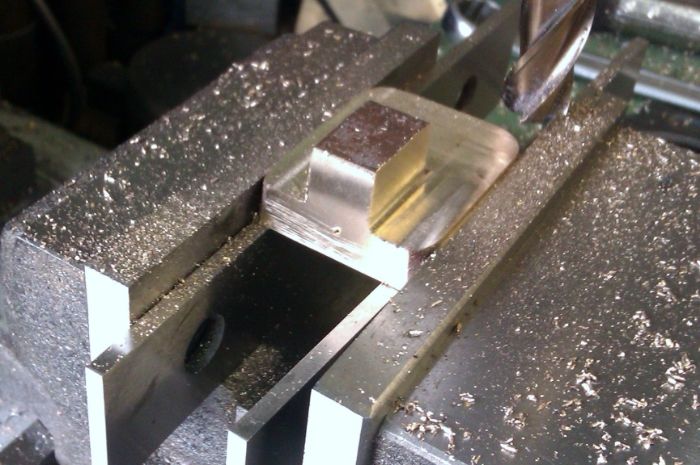
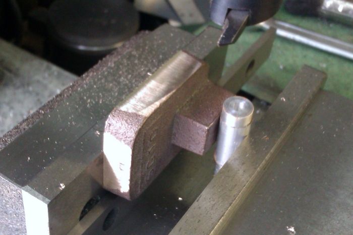
How NOT to Mill the Gunmetal Bearings. What can I have been thinking of, holding them with so little 'Vice Grip' as that..! It seems obvious now of course but the blocks were 'grabbing' at the tool and rising, luck was on my side and I noticed pretty quickly – the original casting size was only a tiny fraction over 1' square if at all. Once I have both Half's faced to the same size on the lathe it will be back to the Mill to do the central channel – held together as one but clamped directly down to the Mill table I think.. As I said though its resulted in my having to go slightly under size to 'square' it back up again..
I've milled the important faces of the Vice itself all over and know that work placed in those vice slots Mill very accurately – caught out with the increase in scale is my excuse..

This is what I'm busy with at the moment. That's 12 faces to do – take quite a while on my little Lathe I expect..

Anyways hope some found it interesting..
Regards.
Allan.
Edited By Allan. on 20/04/2014 11:24:07
 Neil Wyatt.


