A question for anyone who has built the Stuart beam engine.
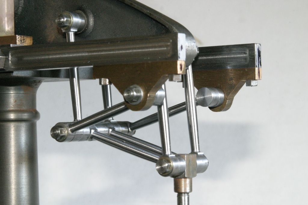
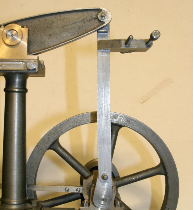
I've started to work again on the one I acquired part built many years ago. I have just finished the links for the parallel motion and have stated to layout the holes in the 1/2" x 5/8" bar for the con rod. At first glance it appears that the 3/8" wide slot in the top of the rod as drawn is not deep enough to clear the beam when at the top of the stroke. The drawing shows the bottom of the slot as 19/32" below the centre of the 3/16" pivot pin hole, which means that the parallel portion of the slot only extends 13/32" below the pin centre (the bottom of the beam is 3/8" wide ) and looking at the beam when at the top of the stroke the bottom looks to be considerably more than that.
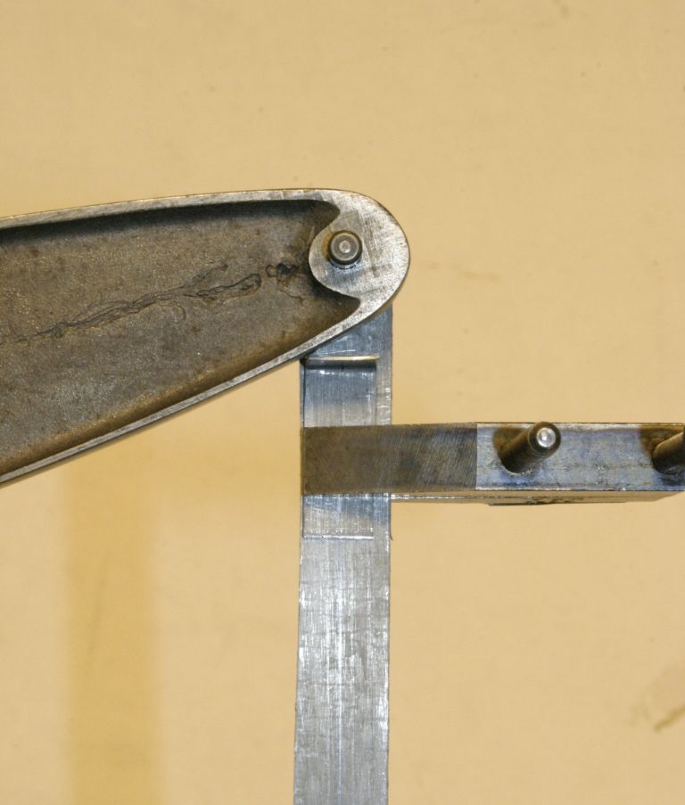
So I made up a dummy con rod to check the clearance and the angled piece on the dummy rod just clears the beam at this distance, perhaps slightly less. It looks like the 19/32" dimension should be to the centre of the radius of the semi circle at the bottom of the slot, not the bottom. I have searched the site for any mention of this but found nothing. Am I missing something?
A quick measure of mine put sit somewhere between 5/8" and 21/32" to the bottom of the slot which still comes quite close so I would say 11/16" would be a safe minimum.
Jason
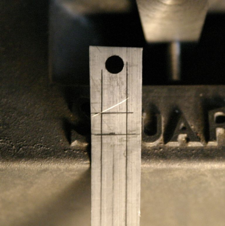
Thanks for your reply. Since my post I tried a different method of determining the depth of the slot. With the beam at the top I scribed a line on the dummy rod along the bottom of the beam. I then drew a line horizontally where it intersects the left hand vertical line that represents the edge of the 1/4" wide fork and another line 3/16" lower to represent the bottom of the curved slot. The distance from the centre of the upper pivot hole to this lower line is just over 11/16", which agrees with your estimate of the minimum dimension. Barring any other suggestions I think I will go with a dimension of 23/32 or 3/4" to give some clearance. I wonder how many connecting rods have been scraped by being made to the plan dimensions?
John
It's too long ago to remember why mine is bigger or whether I had to make another?
I did look at the couple of versions of the Victoria drawings that I have and the dimension is different between the two and one is to the bottom of the U the other to ctr line., I now only have the book for the beam drawing which is as you detail but wonder if there are any differences on the actual drawing(s)
Long time ago for me too, but mine measures about 13/16" to the bottom of the radius.
Maybe I was just leaving myself a load of room, and it looks as if I made the fork as a separate component – but I can't see that it has any negative effect.
The parts list I have is dated 1972 so I would think the plans, although not dated, are of the same vintage. The plans show the dimension to the bottom of the slot as 19/32", the same as in Andrew Smith's book (1987 edition ). This is definitely too short and would foul the beam before it reached the top of the stroke. If the 19/32" was to the centre of the U it would probably just clear the beam. I would be curious to know what the current issue of the plans show for this dimension?
John
Author
Posts
Viewing 7 posts - 1 through 7 (of 7 total)
Please log in to reply to this topic. Registering is free and easy using the links on the menu at the top of this page.