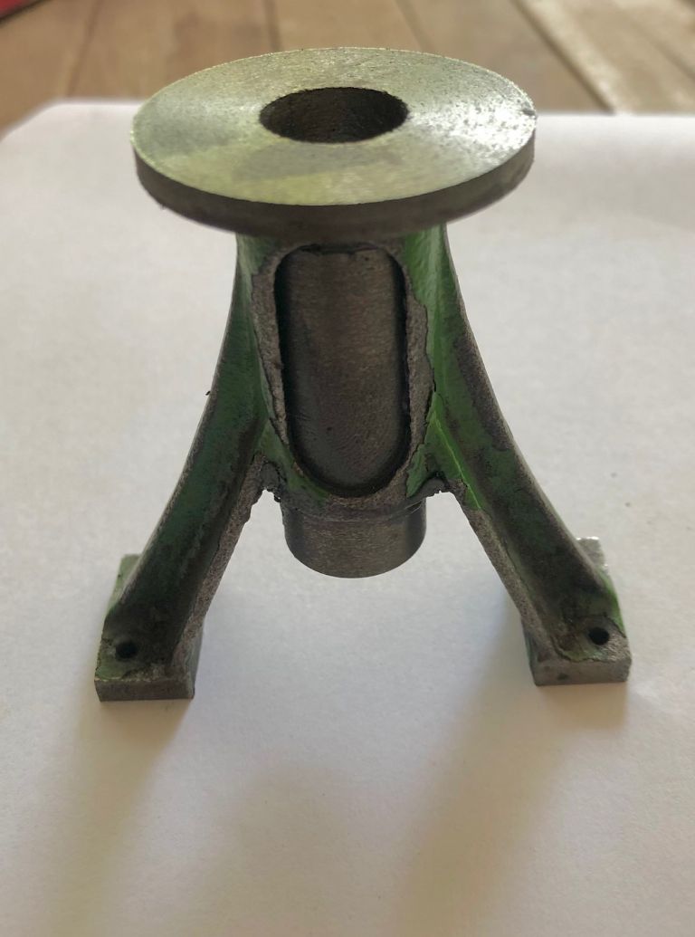
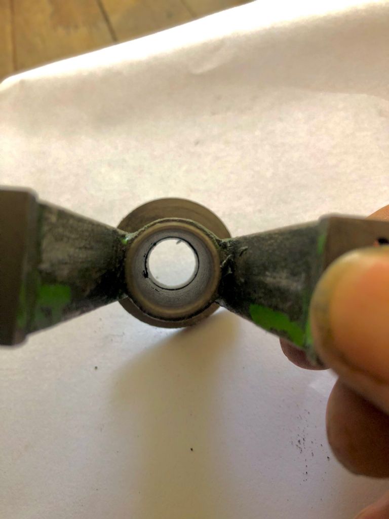
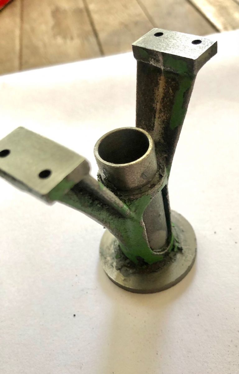
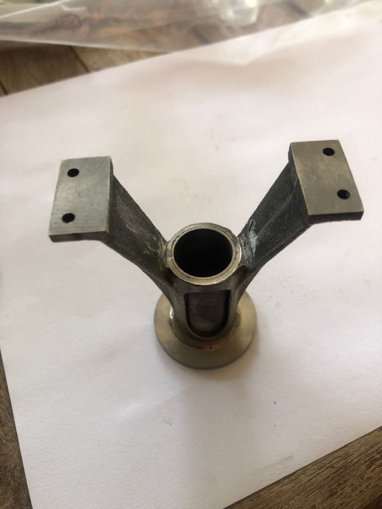
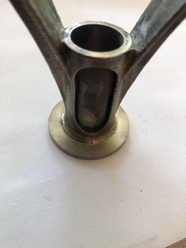
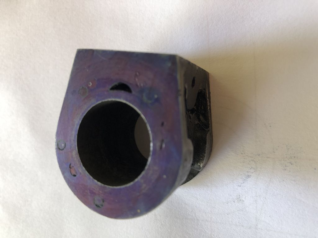
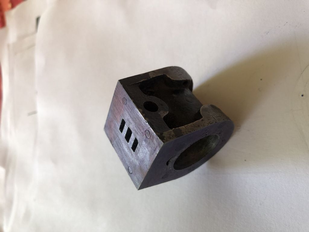
This morning almost finished the standard just to remove sleeve from the side ports, haven't decided whether to mill them away or drill and Dremel them away and a little fettling.
I have removed all old paint and have to now think what paint to use as I am in Thailand it is a bit short on choice, i can use Tamiya paint that is used in models but I need to check if it is good with metal first, it does say it is enamel.
Next, is the color will it be Stuart green or a Maroon, any suggestions?
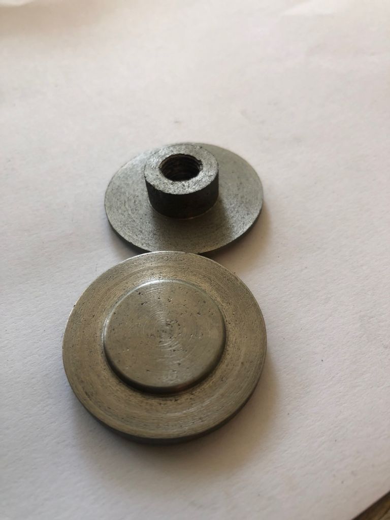
A bit of a schoolboy mistake today on the bottom cylinder cover I was finishing off and I thought that I still had some metal to remove on the thickness so instead of taking it out of the recessed aluminum to check I had 1mm in my mind and it was removed so I will be looking for another bit of cast iron to make a new one a bit of a case of too much hurry and not cross-checking felt a bit stupid with this one.
All in all, i am quite pleased with the outcome so far.
Having now in my possession the book "Building a Vertical Steam Engine from Castings" 1988 edition by Andrew Smith.
I notice that the book does not give dimensions for the marking out of the cylinder Bore and the length of the cylinder is marked as 28.5mm or 1.125 this conflicts with another unofficial drawing I have which says 30mm. I do believe that the 30mm may have been for the builder's requirements and that 28.5mm is correct. I have at the moment a cylinder casting length (Machined) of 30.47mm or 1.200" so I have sufficient material to be able to square and clean up the cylinder when carrying out the reboring procedure.
The center of the cylinder bore I have from another source is 25/32" from the port face and obviously central to the dia of the casting, I believe this to be correct.
The next move is to plug the existing bore with a suitable material this will allow me to correctly mark out the correct positioning of the bore and the holes for the flange fixings. I can see from my rough measurements that I have a bore that is off-center by more than 1mm .039" as suggested by Jason in a previous post I will rebore the cylinder and plug. it with a cast iron insert of a diameter large enough to cover the existing error so I have full walls on the new cylinder bore, this I believe is possible as there is sufficient wall thickness to the cylinder casting.
I have just finished machining the cylinder and the covers for a Stuart 10V engine. It's been hidden under the bench for years in its original packing. In some ways I could have wished I had left the length of the cylinder a bit oversized to accommodate a slightly longer spigot on the 3/4" diameter of the covers.
To my mind a spigot length of only 1/32" is a bit mean. It means that the lathe tool has to have a sharp corner as there is no room for an undercut on the diameter to clear the corner of the cylinder bore. You cannot put much of a chamfer on the bore otherwise you lose the location. I suppose that I could have cut a relief into the face of the cover rather that the diameter, but I did not think of that solution until after I had finished the machining!
As it is, I have made my spigots a rather "full" 1/32" long and intend to adjust other dimensions to suit. The 5/8" diameter spigot at the other end of the lower cover is no problem as it is long enough to accept a small undercut in the corner.
My original Stuart Turner drawings for the engine had the dimensions from the cylinder centreline to the port face and the port face to the exhaust port missing. All the dimension lines, complete with arrows are there, just no numbers. I have a copy of the original Edgar Westbury book of the build, which a got at the same time as the castings, but even he got at least one of those dimensions wrong. I notice that the latest version by Andrew Smith has some anomalies on the dimensions, so do check thoroughly before you cut metal if you are using either of these books.
Top pattern does nor really matter, on that size engine 4,5 or 6 would do provided you arrange them to clear in inlet passage.
There is nothing in the reversing gear that really needs castings, not done it for that engine but done the valve gear for a lot of others without castings.
The original Stuart Turner (Henley) drawings for the 10V and 10H gave 6 holes for the top cover and 4 for the bottom cover. The later drawings give 5 holes for both covers.
When I machined mine I did 5 holes on the top cover, but retained 4 holes for the bottom cover as my castings are very old and the two ribs on the standard go right up to the top flange. This would mean that two of the holes would be very close to these ribs, making the nuts awkward to fit. I did not want to machine these ribs away as I thought that it looked better with them, I am not intending to fit drain cocks on this model so the position of the holes was not an issue.
Lately I have been waiting for digital readouts arriving from China and of the three I ordered for the mill two have arrived, this has slowed me down a bit although I have just completed fitting the two to the mill, the electronic components for the touch DRO are also with me so as a side project I will be working on this upgrade and keep you informed of the progress.
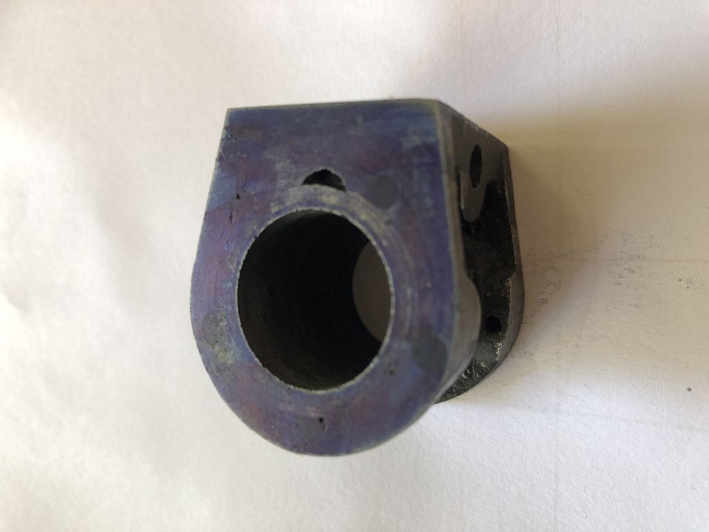
I have plugged all the existing holes in the cylinder with threaded rod and JB weld (great stuff Jason) I also included the cylinder these are all now completed and the cylinder casting is now true and on length. The replacement cylinder cover has also been remade. Next on the cylinder casting is to finish machine the port face to the correct dimension.
I have also decided to laser cut the gaskets out of HDPE sheet which is available in a choice of thicknesses from AliExpress, when they are done I will be able to place them on the cylinder and choose the hole number based on what hole spacing gives me the solid metal. Then proceed with drilling the cylinder and covers.
The older drawings that I have show 7/32 & 1/4", the later drawings have the chest at 1/2" and valve rod central
The extra 1/32" from port face to ctr line gives the valve room to lift off the surface and prevent hydraulic lock, steam or air pressure is what holds it to the port face not the valve rod.