Stuart 10V rebuild

Advert

Stuart 10V rebuild

Home Forums Stationary engines Stuart 10V rebuild

Viewing 25 posts - 1 through 25 (of 38 total)
  • Author
    Posts
  • #616891
    Jim K
    Participant
      @jimk

      Hi All,

      I acquired a old Stuart 10V and on inspecting it in preparation to run I realised this was not likely to happen due to the very poor workmanship.

      I hope to show you all the issues and what I done to rectify the faulty parts, I will welcome advice from you all during the rebuild.

      there will be decisions I will have to make in the early stages whether to work in imperial or metric although I think there will be a bit of a mix in the dimensioning to allow me to use available material.

      we will see how it goes.

      Advert
      #3503
      Jim K
      Participant
        @jimk

        Stripping and rebuilding a badly made 10V

        #616895
        Thor 🇳🇴
        Participant
          @thor

          Hi Jim,

          I built a vertical steam engine based on the Stuart 10 Standard and Cylinder, see here, that you may find useful. Good luck with the rebuild.

          Thor

          Edited By Thor 🇳🇴 on 11/10/2022 11:29:17

          #616899
          Jim K
          Participant
            @jimk

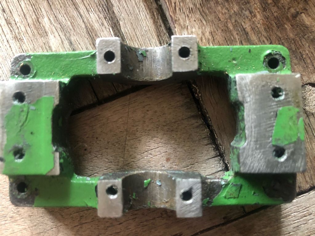
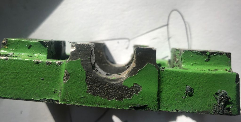
            In the bottom two photos, I have three issues to deal with.

            1. The seatings for the Main bearings are hand filed and are oversize, in order to ensure that they are both in line I will probably machine out the seatings so they have square bottoms this will allow me to machine a suitable piece of brass as the main bearing journals.

            2. The holes on the seating for the main bearings are not aligned, I will drill these out and plug.

            3. On the left side there is a step on the engine standard seating also on measuring the height it has not been filed even giving varying heights, I will re-machine this soleplate just enough to clean it up around .5 mm(.015&quot,I believe this should not make a difference as long as the measurements for the bearing holes are as per the drawing.

            image2.jpegimg_8307-2.jpg

            Edited By Jim K on 11/10/2022 11:48:05

            Edited By Jim K on 11/10/2022 11:48:32

            #616900
            Jim K
            Participant
              @jimk

              Thor,

              Thank you that information will be very helpful.

              #616902
              JasonB
              Moderator
                @jasonb

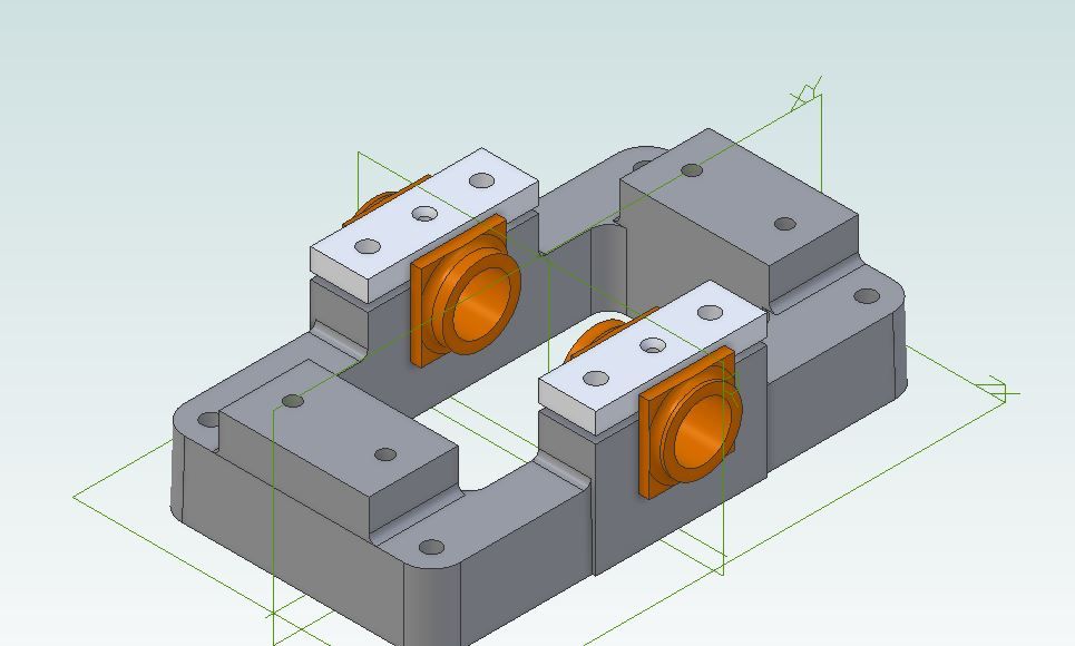
                That plan should work, looks like at least one of the bearing retaining stud holes will need moving over too. I'd plunge out with a milling cutter on the right position and loctite in a plug.

                If you go with the square bearings then just some simple flat bar will do for the caps. One I prepared earlier.

                10v alternative.jpg

                #616903
                Thor 🇳🇴
                Participant
                  @thor

                  Hi Jim,

                  Your 10V doesn't seem to be machined with much accuracy. I did machine the seatings for the bearings with square bottoms on mine (but I used stock material for the Soleplate, not the Stuart casting). For an engine that is not going to do heavy work brass should do as bearings material, I have used that on several of my models.

                  Thor

                  #616904
                  Jim K
                  Participant
                    @jimk

                    Jason,

                    Nice one, I was not thinking of that design I was thinking of the bearing including the flange for bolting it down machined into it so it is like a t shape.

                    #616906
                    Jim K
                    Participant
                      @jimk

                      Thor,

                      I want to try and make all parts I replace on the engine just like you have stated rather than purchasing castings.

                      There is an interesting photo coming tomorrow showing the engine standard it is a mess just like a Swiss cheese with all the holes.

                      #616907
                      John Rudd
                      Participant
                        @johnrudd16576

                        There is a new unused engine standard in the FS section……

                        #616955
                        Colin Heseltine
                        Participant
                          @colinheseltine48622

                          I had a similar 10V. If you have a look on Model Engine Maker website you will see the issues I faced and how I overcame them. Follow links below:

                          https://www.modelenginemaker.com/index.php/topic,10180.msg231644.html#msg231644

                          Best of luck, it will be worth it.

                          Colin

                          #616956
                          JasonB
                          Moderator
                            @jasonb

                            You will need to register to be able to see Colin's images as they are posted as attachments which guests can't see.

                            #616957
                            Colin Heseltine
                            Participant
                              @colinheseltine48622

                              Thank you for that Jason. I had not realised they would not be seen.

                              Colin

                              #617093
                              Jim K
                              Participant
                                @jimk

                                Hi All,

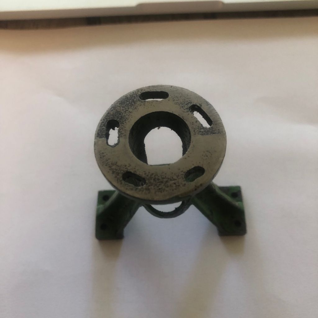
                                I am including today a photograph of the standard and the cylinder to highlight the issues I have to deal with in these two parts.

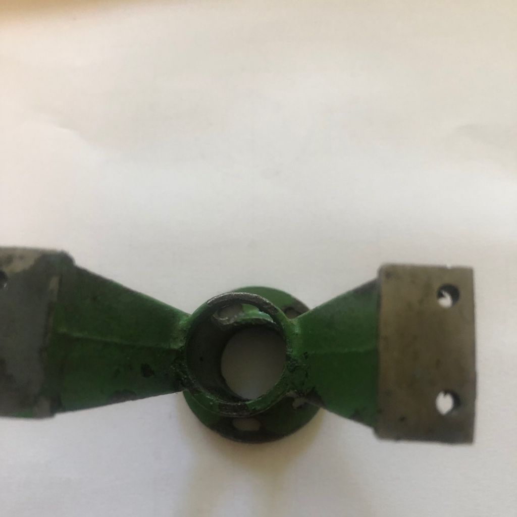
                                The Standard

                                1 The bore of the standard should be 16mm or 5/8" it also should have 4 holes on a PCD of 28mm 1-1/8" I have 5 slots to deal with on this standard.

                                The height of the standard is 70mm 2.763" so I have some metal I can remove as the drawing standard height I understand is 68mm 2-11/16"

                                For the bore I am not sure what approach I should take as there is not a lot of wall thickness to enlarge the bore, I could true it up on the lathe and just ensure it is round and clean it up a little, not the ideal solution.

                                For the flange, I will either have to plug up the slots or I am thinking to machine remove the flange and turning a spigot with a shoulder to receive a new flange, the new flange could be silver soldered to the standard and then machined to the final size.

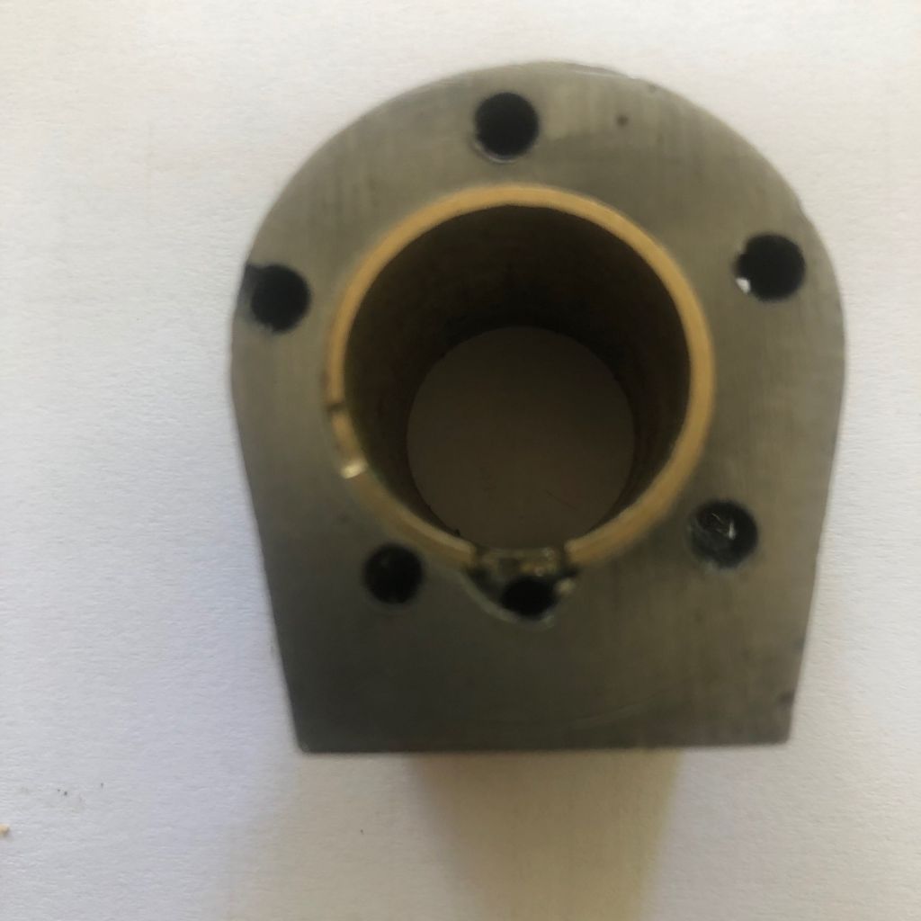
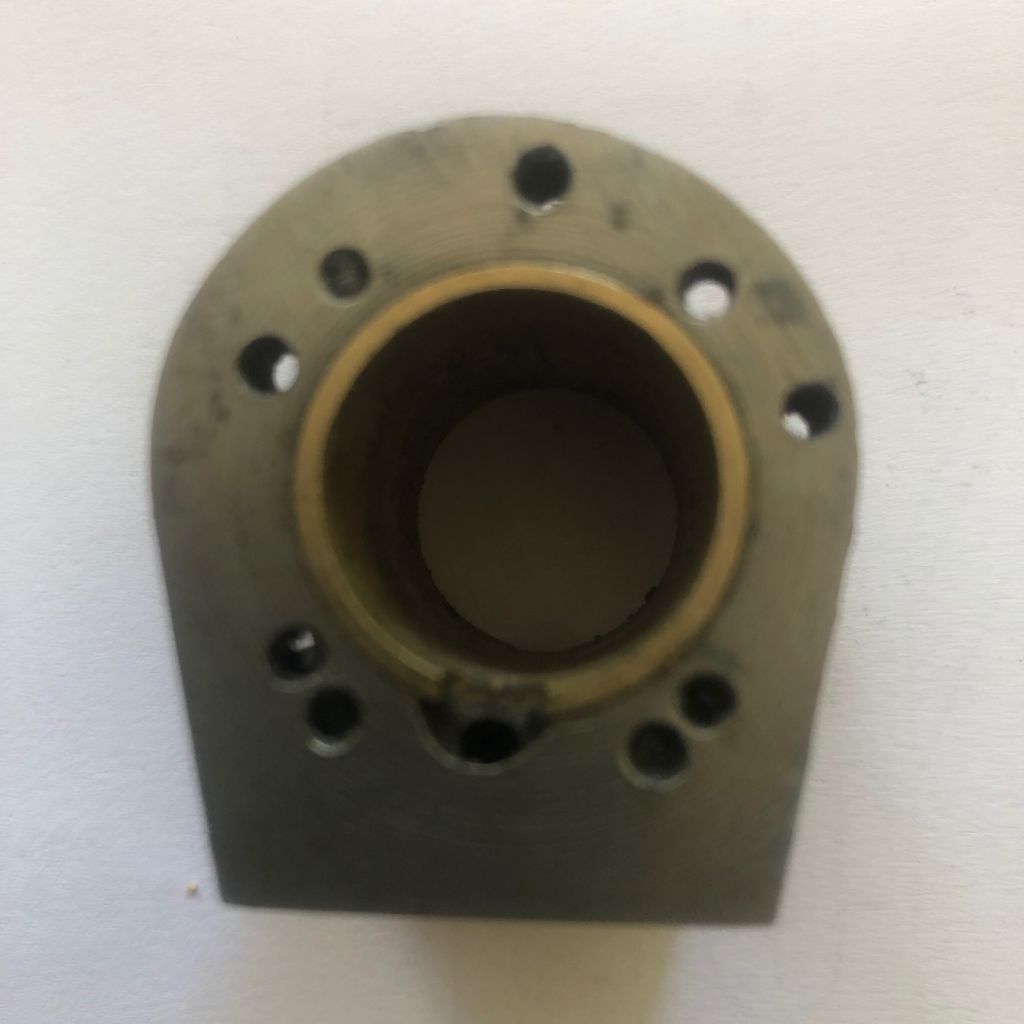
                                The Cylinder

                                As you can see the cylinder needs some love and care to restore it to what it should be.

                                The bore has a brass sleeve with a bore of 18.59mm .731" it must have been machined oversize when it was made looks like it could have been 21.35mm .840" before sleeving, wouldn't mind some suggestions on this one.

                                The length of the cylinder is 30.60mm 1.204" this should be 28.5mm 1/1/8" so I can remove metal from both faces to ensure that both faces are parallel and to the correct size.

                                For the holes in the cylinder, the best approach would be to mark them up and see if any of the holes are in the correct position the remainder is to be plugged using a threaded rod and the holes are redrilled in the correct positions.

                                For both these faces due to the current positioning of the holes, I do not see many where the holes will be converging with the newly positioned holes.

                                standard.jpgstandard 1.jpgcylinder.jpg

                                cylinder1.jpg

                                For the future i will improove the quality of the pictures.

                                Edited By Jim K on 13/10/2022 04:25:10

                                #617097
                                JasonB
                                Moderator
                                  @jasonb

                                  For the standard I would consider removing the flange completely. Then from CI or steel machine a solid insert with integral oversize flange. JBWeld that into the existing oversize trunk guide and when set proceed to machine it as a new casting with the additional operation of milling two slots in the sides. At a little over 1.3mm wall the insert will have sufficient strength and as it is "held" by the casting won't distort during machining. There is an option to do this in two, ask if you want details

                                  As for the cylinder that bore looks to be well off to one side so I think I would sit down and have a good measure and marking out session to see if it can be pulled into the right place, if not get a bit of CI bar and care a new one from solid or fabricate from bronze and brass

                                  If it can be pulled over then I think I would set it up with the existing bore running true and bore out the brass sleeve to leave a clean surface so a turned solid plug of CI can be loctited into place. Then set the cylinder to run with it's bore properly centred and take out to 3/4" skimming the flange end of the cylinder at the same setting. Then clamp that end down to the mill table and square the other end to it.

                                  As for the holes I'm not keen on pluging and drilling close to the edge of a plug particularly if different metals as drills can wander. I would clock in the now trued bore and plunge cut with a 5mm milling cutter at each hole position and JBWeld in some 5mm brass inserts which have previously been tapped 7BA or M2.5 as you prefer.

                                  What is the port face like?

                                  #617112
                                  Jim K
                                  Participant
                                    @jimk

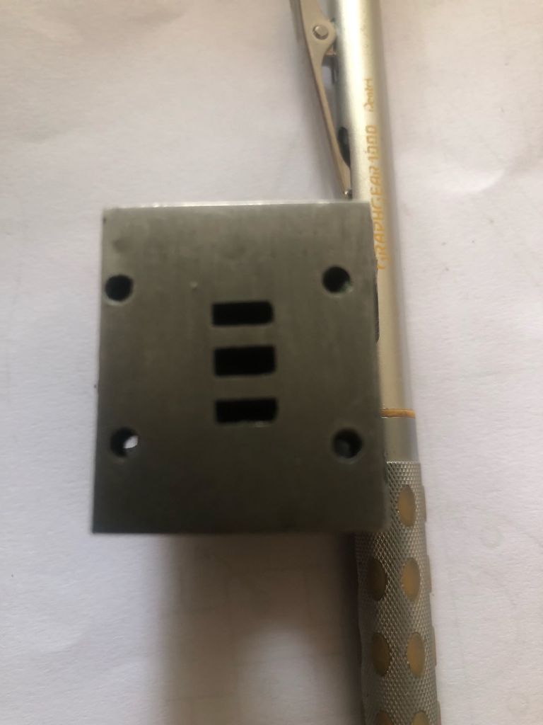
                                    Jason,

                                    The port face looks OK except that the holes are drilled in the wrong positions, as you can see in the picture below. these will be easily plugged and repositioned.

                                    As for your suggestions in your post, I believe your idea will work, I was a little bit concerned about the wall thickness of the standard guide, about using JB weld which I had not thought of as I thought it was an American product.

                                    All in all, I will work on your approach to correcting the casting.

                                    port face.jpeg

                                    #617131
                                    JasonB
                                    Moderator
                                      @jasonb

                                      Regarding the JBWeld, just make sure you get the "original formula" not the rapid or marine as they don't have such a high temperature rating should you want to run on steam.

                                      Another option for those stud holes for the valve chest would be to just fill them and drill in the corners as per the drawings. Only downside to that is if you want to use the same chest cover you will see the plugged holes in that.

                                      #617208
                                      Jim K
                                      Participant
                                        @jimk

                                        Jason,

                                        Looking closely at the options for the standard, I can get a small dia cast iron rod which can be machined to suit the standard bore and as I believe it is better to keep it as cast iron, I would like to hear your suggestion for machining the insert and the flange separately.

                                        The standard measures 70mm 2.759" in height, like you have stated new insert, New flange and start out as if a new casting would be the way forward.

                                        #617209
                                        Blue Heeler
                                        Participant
                                          @blueheeler

                                          Following this thread.

                                          #617270
                                          JasonB
                                          Moderator
                                            @jasonb

                                            There are a couple of options for the two part repair, one can be done with a single glue up session the other will need a second dose of the JBweld or could be Loctite but does offer a larger surface area to bond.

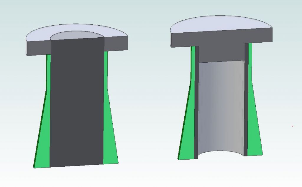
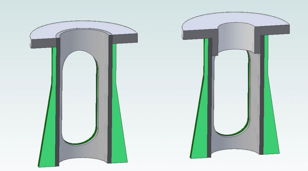
                                            On the left the standard has had the barely skimmed and the flange turned off flush. A n approx 18.75mm cylinder of CI inserted that extends say 5mm above the lower flange height. A ring of iron or steel 5mm thick is bonded to this protruding section and the top of the standard.

                                            On the right the standard is prepared the same way but a shorter CI plug added and when set bored out to 5/8" or 16mm as you prefer. After that a 5mm flange with a 6mm long spigot is bonded into the bore of the guide and to the top of the standard. I would have this spigoted gland turned ready to bond in once the standard has been rebored to save having to rechuck (faceplate) it so everything stays concentric to the standard's bore.

                                            10v standard.jpg

                                            You can now bore the one on the left out to 5/8" or 16mm and face the flange back to thickness I would aim for this to leave the standard 0.5mm over height.

                                            The one on the right can again be faced back to the +0.5mm and the hole opened up to 12mm*

                                            10v standard machined.jpg

                                            I would then clamp the flange to the mill table and skim 0.5mm off the feet to true them up and bring the standard to height. Complete by milling the side slots and drilling the FOUR holes 7ba clear in the flange

                                            * the spigot on the lower cylinder cover will need to be reduced from 5/8" to 12mm to fit this hole. Assuming the cover is as well made as the rest then a new one will be wanted to ensure the piston hole and gland hole are concentric to the spigot that fits the cylinder bore.

                                            #617346
                                            Jim K
                                            Participant
                                              @jimk

                                              Jason,

                                              The LH option was what I had in mind, although the RH one looks stronger,

                                              Another issue I have found that the cylinder appears to have been machined presumably on a rotary table (don't know what possessed the builder to do that) the cylindrical dimension on the cylinder is now 33.51mm 1.319" and I presume it was originally 35mm 1.375" approximately as it is a casting. This should not affect the build other than making the top and bottom covers suit the cylinder diameter keeping everything uniform.

                                              I keep wondering as I go through this rebuild if I will ever find anything that is a correct dimension, well I suppose if it was easy it would be no fun.laugh

                                              Currently I am waiting for delivery of a rotary table (should arrive today) and some other bits and pieces i require for the project, I also have to get BA taps and dies, as i am in Thailand it will be easier to buy a set on ebay and get my mate to bring out end of next month.

                                              #617353
                                              JasonB
                                              Moderator
                                                @jasonb

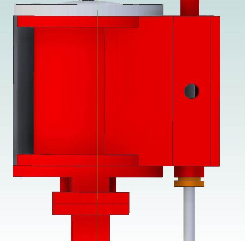
                                                Having the diameter of the cylinder's flanges a bit smaller than the covers is quite common and no bad thing as it allows any cylinder lagging to sit flush with the OD of the covers. You can hopefully see here how the dark cladding sits against the cylinder flanges which form a recess for it to fit into.

                                                lagging.jpg

                                                #617454
                                                Jim K
                                                Participant
                                                  @jimk

                                                  Thanks for the feedback, I had forgotten all about the cladding and the option to allow it to be flush with the cylinder covers.

                                                  #617644
                                                  Dr_GMJN
                                                  Participant
                                                    @dr_gmjn

                                                    I also made the valve chest a bit wider than the valve face on mine do that the cladding fitted flush all the way around.

                                                    #618716
                                                    Jim K
                                                    Participant
                                                      @jimk

                                                      Progress has been slow due to the delivery of tooling and leveling of the lathe bed.

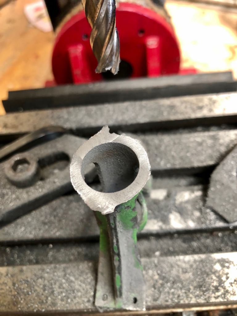
                                                      I machined a sleeve for the bore of the standard and a new flange all from cast iron these were machined on the OD of the sleeve and the spigot to suit the existing bore of the standard, I left metal on the bore of the new parts for final machining once fixed in place using the JB weld as suggested by Jason.

                                                      I will be adding a picture later showing the flange and new sleeve fitted.

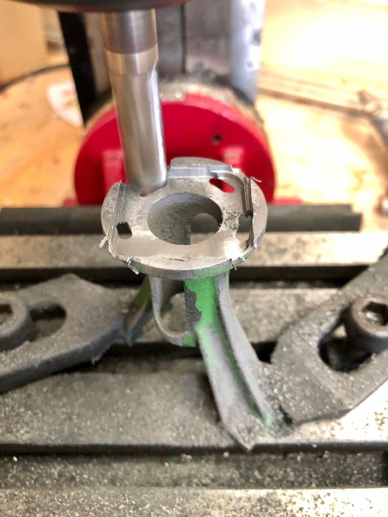
                                                      The standard was placed in the lathe and gripped by the flange then trued up to the casting, I then skimmed the feet of the standard to clean up the surfaces and make them flat and true.

                                                      Once cleaned up the standard was fixed to the mill to prepare for the removal of the flange as can be seen in the pictures below.

                                                      removing flange.jpg

                                                      Removing the flange on the Mill

                                                      flange removed.jpg

                                                      Flange removed

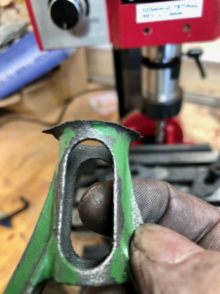
                                                      leaving fillet.jpg

                                                      The above picture shows the underside after the removal of the flange as can be seen I have left the fillet to blend it to the new flange after fitting.

                                                      As I get the required material and the rotary table fitted the pace should quicken, I have also ordered those DRO scales to adapt to using touch DRO which calls for me to get a few electronic components and a circuit board another project on top of other existing projects, Am I the only one that does that.frown

                                                    Viewing 25 posts - 1 through 25 (of 38 total)
                                                    • Please log in to reply to this topic. Registering is free and easy using the links on the menu at the top of this page.

                                                    Advert

                                                    Latest Replies

                                                    Home Forums Stationary engines Topics

                                                    Viewing 25 topics - 1 through 25 (of 25 total)
                                                    Viewing 25 topics - 1 through 25 (of 25 total)

                                                    View full reply list.

                                                    Advert

                                                    Newsletter Sign-up