Stuart 10V Build Log – Complete Beginner…

Advert

Stuart 10V Build Log – Complete Beginner…

Home Forums Work In Progress and completed items Stuart 10V Build Log – Complete Beginner…

Viewing 25 posts - 201 through 225 (of 385 total)
  • Author
    Posts
  • #482528
    Dr_GMJN
    Participant
      @dr_gmjn

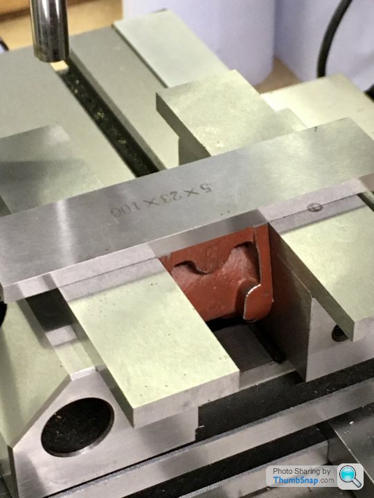
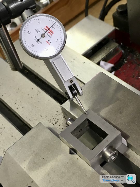
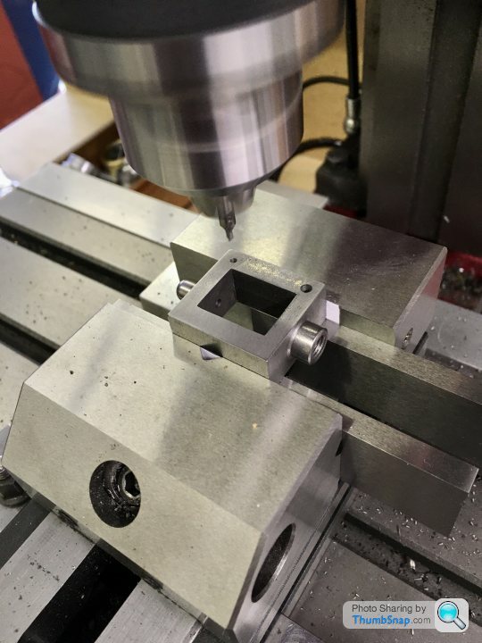
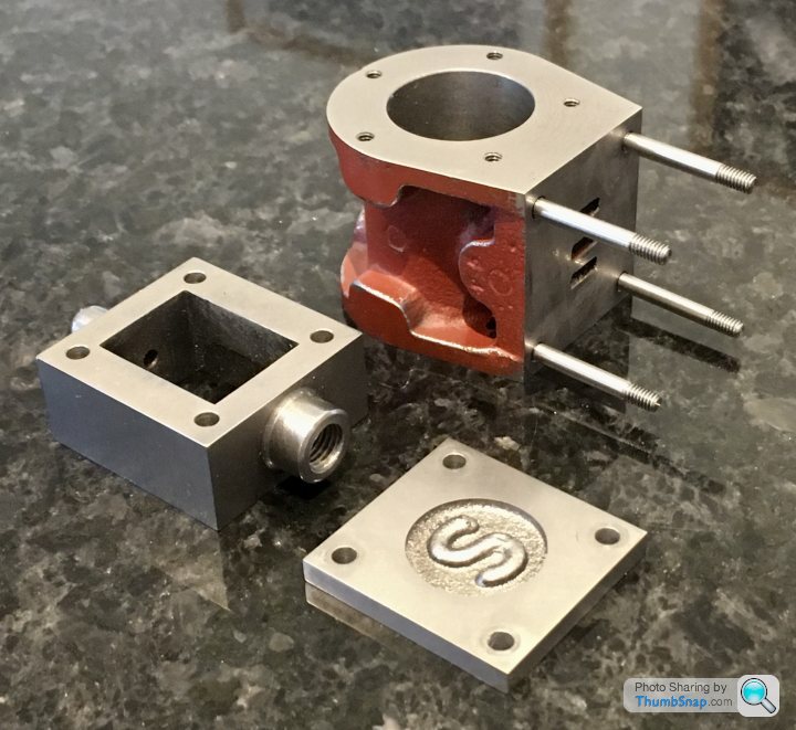
      So on to the valve chest fitting. Began by clamping the cylinder in the vice using some parallels to get the top face flat:

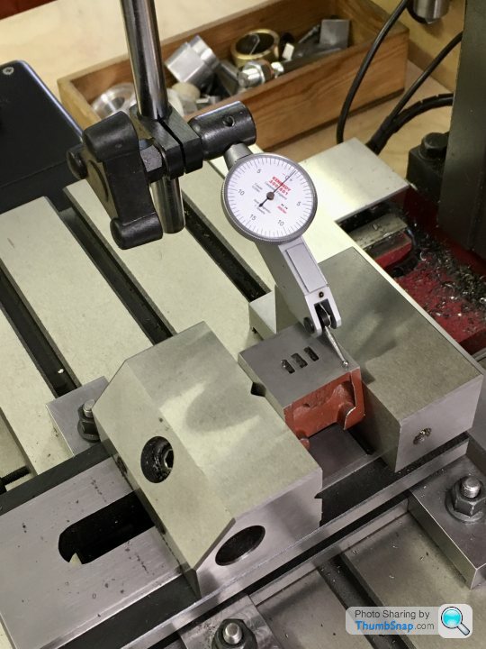
      Checked for flatness:

      And got the centre using the edge finder:

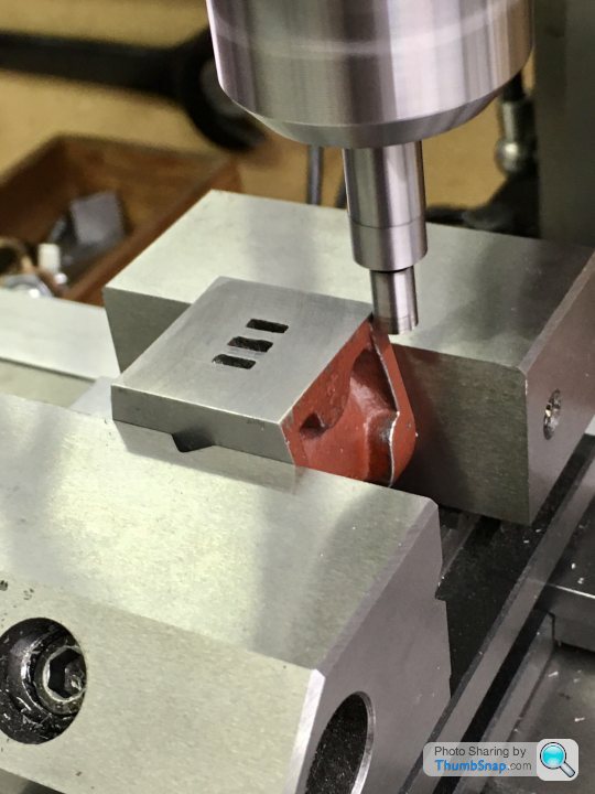
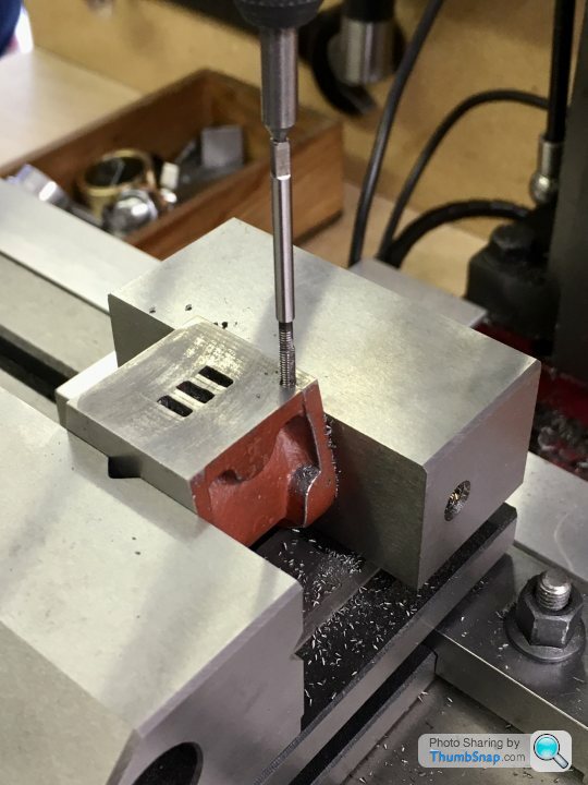
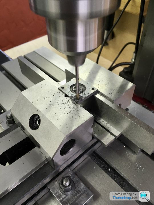
      Then co-ordinate drilled and tapped in one setting using the DROs:

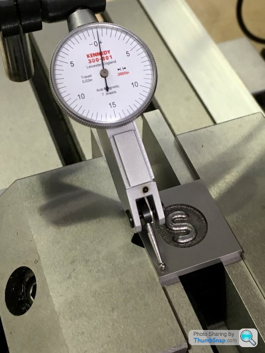
      Same with the valve chest:

      And the cover:

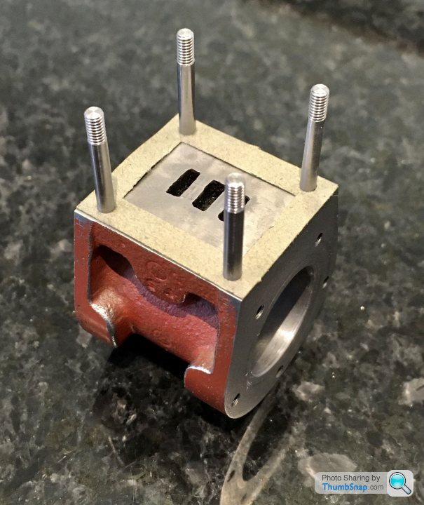
      Fitted the studs temporarily:

      Gaskets fit, so must be about right:

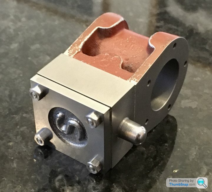
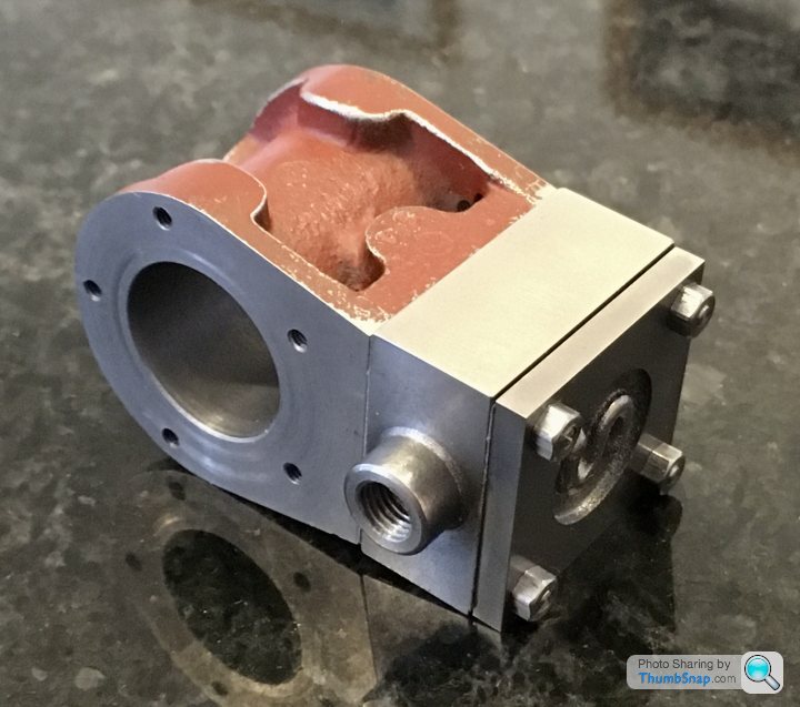
      It all slides together nicely, and seems to be central:

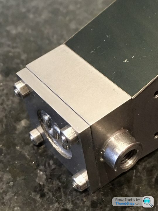
      And the jacket is a flush fit too:

      Next job will be fitting the main bearings and standard to the sole plate.

      Advert
      #482533
      JasonB
      Moderator
        @jasonb

        Coming together nicely, this is where the DRO comes into it's own and spotting through a thing of the past.

        #482552
        Dr_GMJN
        Participant
          @dr_gmjn
          Posted by JasonB on 27/06/2020 15:27:25:

          Coming together nicely, this is where the DRO comes into it's own and spotting through a thing of the past.

          Thanks. Yes, slow, but – sort of sure.

          My lathe work is noticeably worse than the milled stuff in terms of accuracy. I really need to get some DRO’s for the ML7, but all the methods I’ve seen for attaching them look a bit naff and fragile.

          #482633
          Dr_GMJN
          Participant
            @dr_gmjn

            The last casting to be machined is the flywheel. There are several methods suggested in books or online. The simplest seems to be drill and ream the hole and mount on a mandrel.

            Im wondering if it would be better to bore the hole to be a tight fit on the supplied shaft (rather than ream and get a running fit), and then drill the grub screw hole and mount to some spare crankshaft rod using the screw?

            my thinking is that this is how the wheel will be fitted, so why not machine it as such and account for any slight deflection caused by the screw?

            would boring the hole possibly not give a good enough fit in terms of possible taper?

            suggestions welcome as always. Thanks.

            #482635
            Dr_GMJN
            Participant
              @dr_gmjn

              The other thing is – is it best to drill the cylinder drain tap holes before lapping?

              And what is the suggested size for the hole for these that breaks through into the cylinder? Presumably the threaded part doesn’t go all the way through the wall?

              #482652
              JasonB
              Moderator
                @jasonb

                Personally I never machine flywheels on an arbor and it is just asking for chatter and a poor finish. If possible hold by the inside of the rim in either 3 or 4 jaw chuck. Stuarts are usually fairly true once cleaned up with files so 3 jaw will do. This way you can machine the face, 1 side, hub face and then finally bore all at one setting ( I don't ream) then just flip it over to do the other side of rim and hub which don't need any concentricity.

                Drill drains first, 1/16" or 1.5mm hole will do, threaded hole about 1/16 to 3/32 short of cylinder

                Edited By JasonB on 28/06/2020 10:08:58

                #482677
                Dr_GMJN
                Participant
                  @dr_gmjn

                  Thanks Jason, that should keep me busy for a few days.

                  #486462
                  Dr_GMJN
                  Participant
                    @dr_gmjn

                    Got a bit sidetracked with this, but made a start on the flywheel this afternoon.

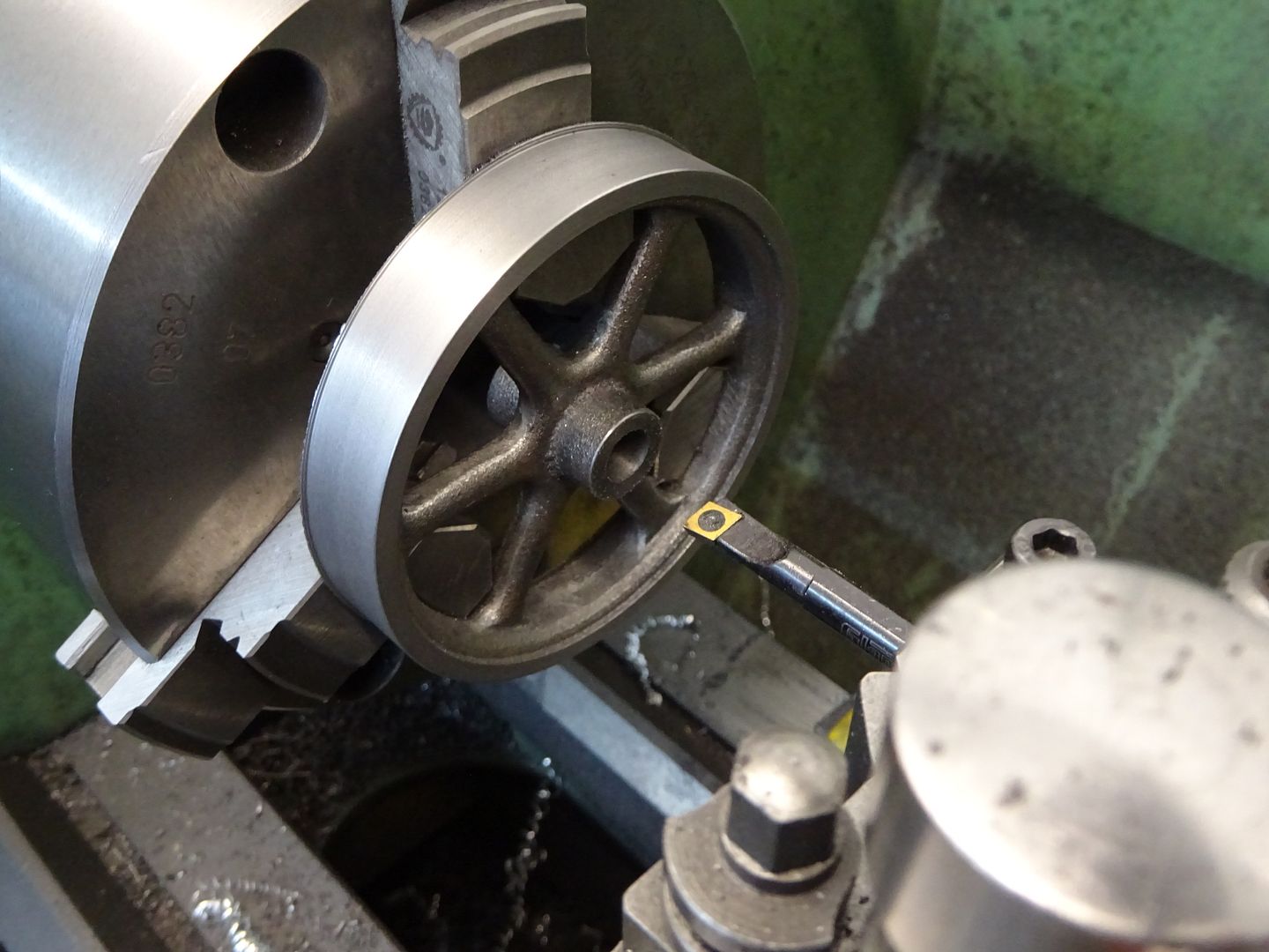
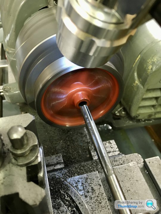
                    Expanded the 3-jaw Chuck to clamp the inside of the rim, and turned true:

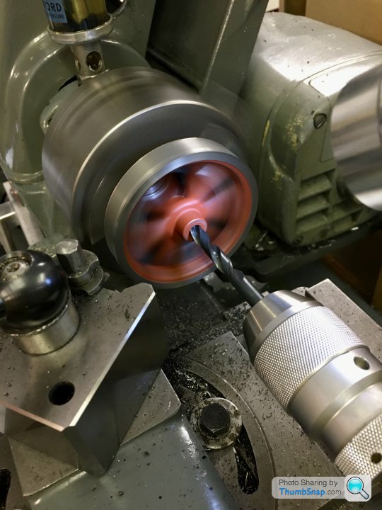
                    Drilled the bore:

                    I do have a small boring bar, but unfortunately it was just too large for the job. I pondered buying one, but instead opted to ream it to suit the crankshaft:

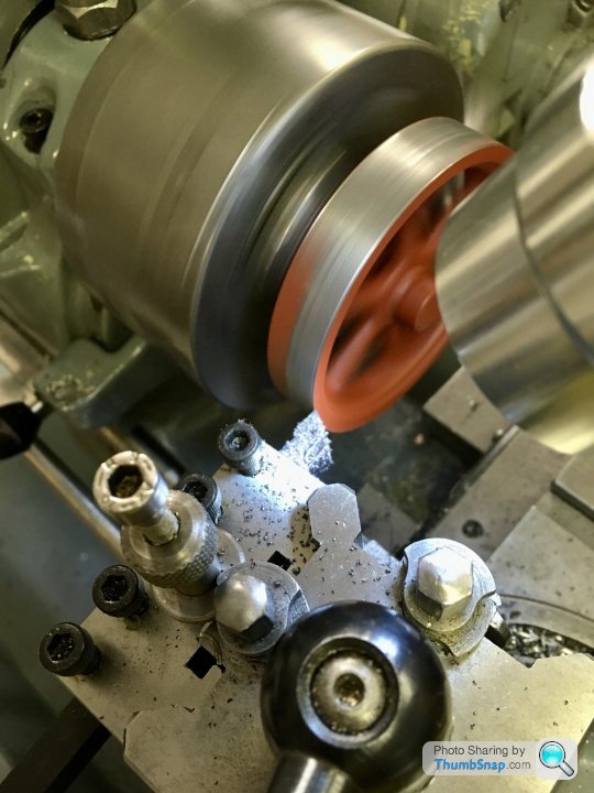
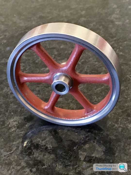
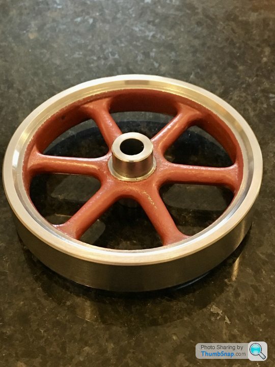
                    And machined the inside rim and boss, then reversed in the chuck and did the other side, as suggested:

                    Fit on the shaft is fine, and thankfully, the features turned on the initial setup are true (at least visually, when spun on the shaft). However, the features on the reverse setup are noticeably off. I suppose a result of the casting not being perfectly uniform. So, I might set it up again in the 4-jaw (clocked to the o/d) and re-do the bits that are off. I don't suppose it matters from a function point of view, it'll just look a bit wrong when running.

                    #486502
                    Dr_GMJN
                    Participant
                      @dr_gmjn

                      So I've done the corrections just in the 4-jaw chuck, all the machined bits seem pretty much spot-on true now, so just needs the screw hole drilling and tapping, then on to the standard and main bearing fitting.

                      #486600
                      Dr_GMJN
                      Participant
                        @dr_gmjn

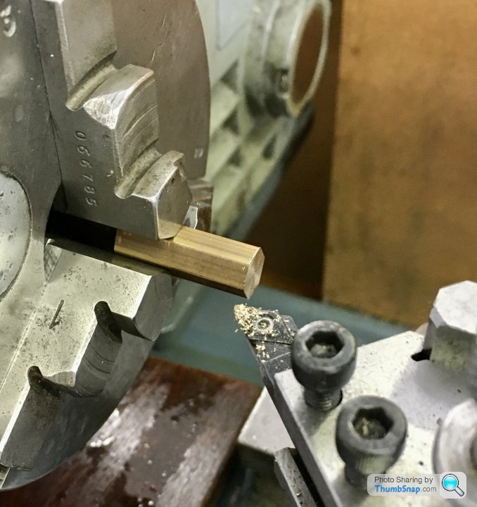
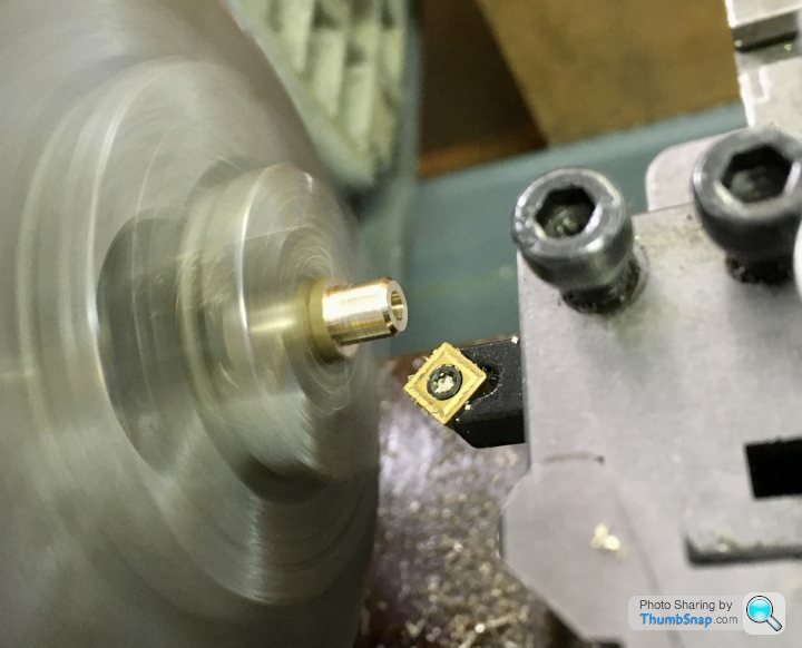
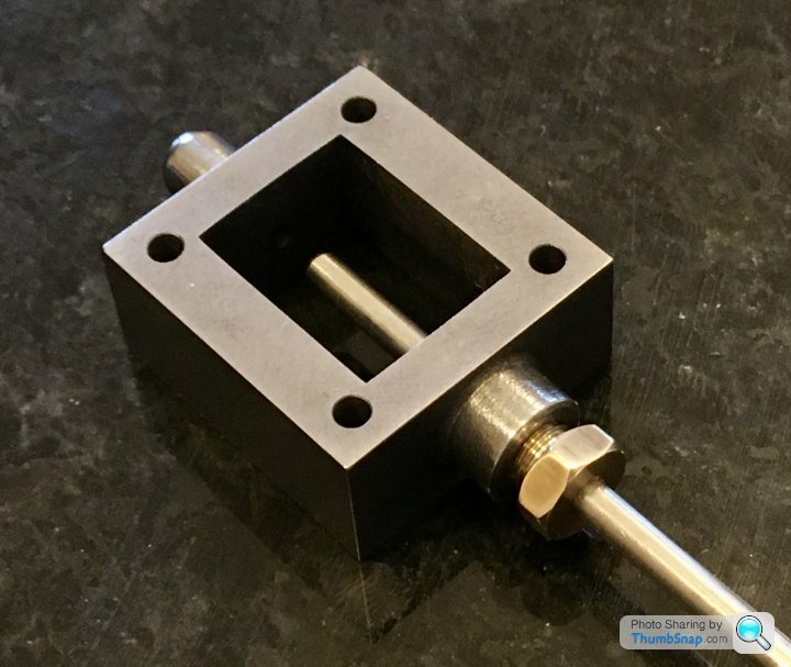
                        Quick bit of turning to get back into it: The valve rod packing nut. It’s turned from some hexagonal bar:

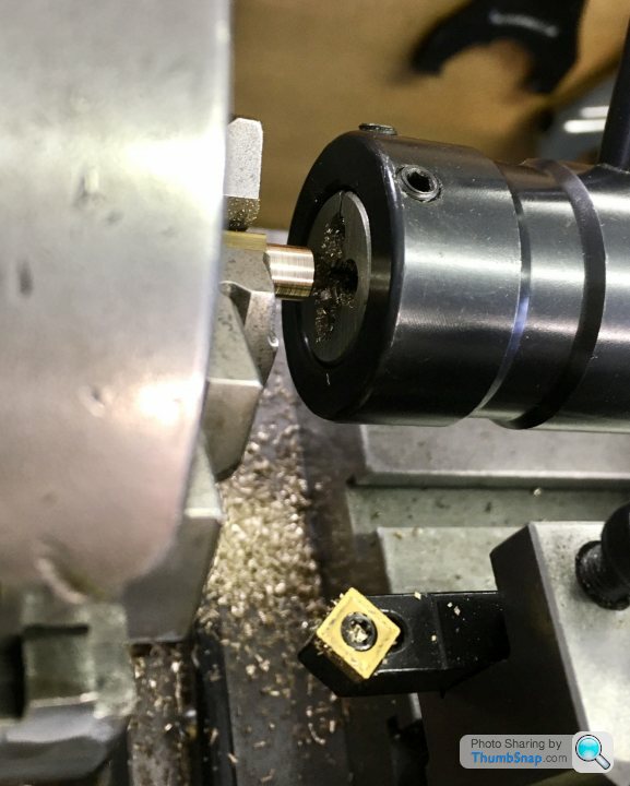
                        Then drilled and reamed to 1/8” to suit the valve rod.

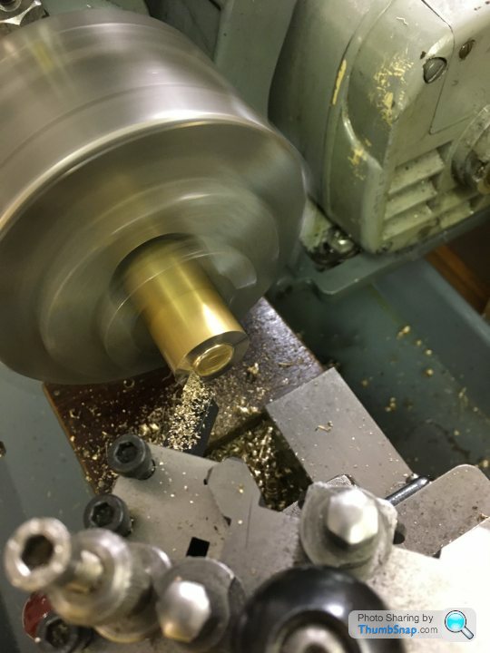
                        Turned to 1/4” and chamfered to give a lead for the die:

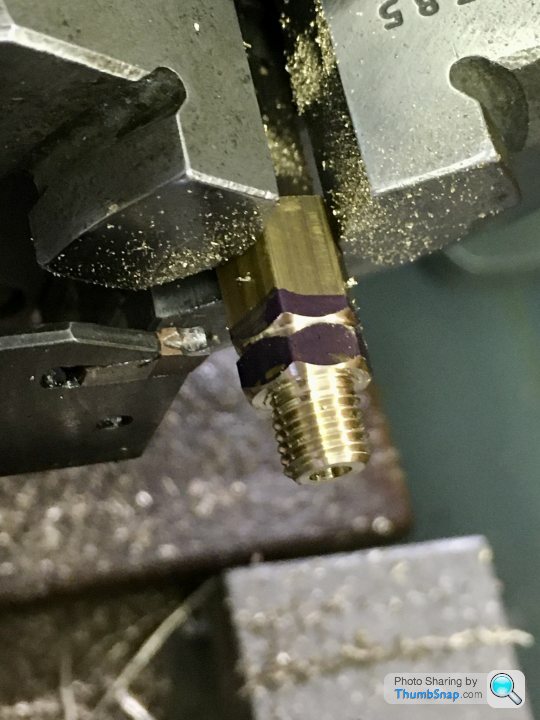
                        Then chamfered the flats and parted off:

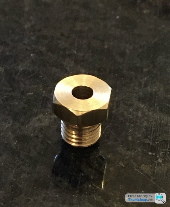
                        Seems to fit ok:

                        #486971
                        Dr_GMJN
                        Participant
                          @dr_gmjn

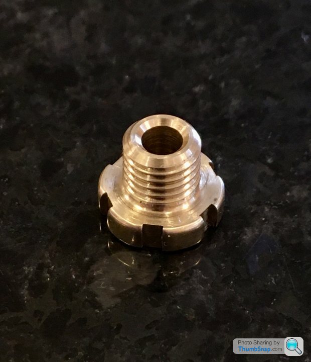
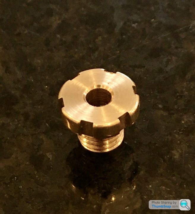
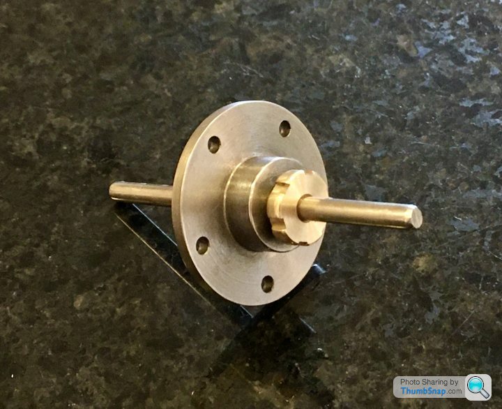
                          The piston rod seal packing nut is a bit different from the valve rod nut; it’s larger, and has screwdriver cut-outs for tightening instead of flats due to it fitting within the standard. It’s turned from the same brass stock suppled for the piston:

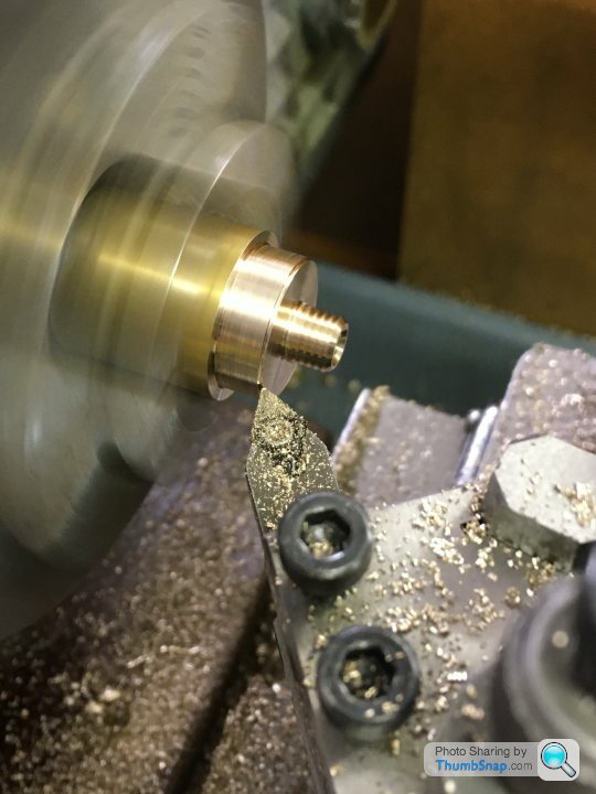
                          Drilled, reamed, threaded, then turned down to size before parting off:

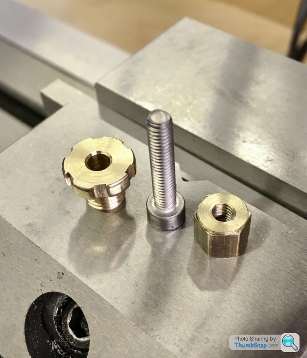
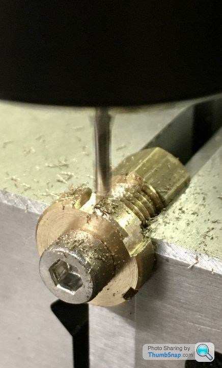
                          There are six undimensioned cut-outs in the O/D. I don’t have a rotary table, so I made a simple fixture out of the remaining hexaganol stock from the valve nut:

                          It’s just sits in the milling vice on a parallel, and the slots milled to 2mm and 0.85mm deep from touching on the diameter. Then move around one flat at a time:

                          Worked OK:

                          The threads are a bit sloppy in their holes, not sure why. I suppose I could use thread lock if they loosen.

                          #486974
                          JasonB
                          Moderator
                            @jasonb

                            You are making good progress. A bit of slack in the gland nut threads won't hurt as it will allow them to self align with the rod should there be any slight misalignment. The compressed gland material should stop then from wanting to unwind.

                            #487018
                            Dr_GMJN
                            Participant
                              @dr_gmjn

                              Thanks Jason. Unfortunately (and somewhat inevitably) this is where it all goes wrong…

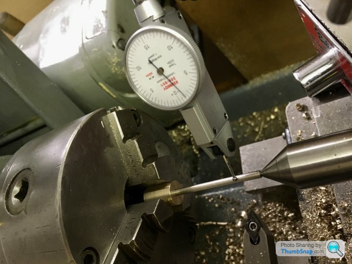
                              The valve rod is stepped, and threaded. First of all I made a split bush to fit the 3-jaw chuck (4-jaw won’t close enough). I got it to within 0.0015” of true, centre drilled and turned the end to be a good fit in the valve chest top as per the image:

                              Not sure if this was the best method, but I didn’t get a particularly good finish on the end. Still, it fitted smoothly enough.

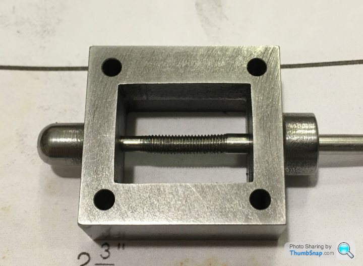
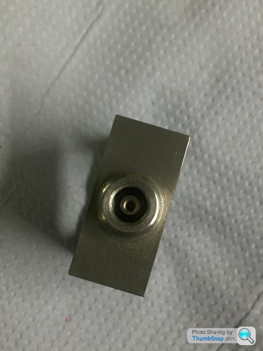
                              Then, the 5BA thread. The die wouldn’t go on the turned-down end. This is where my heart sank as I realised what I’d done. The hole in the top of the valve chest should be 3/32” (2.38mm), but for some reason I’d ended up with 2.75mm.

                              The root diameter of the 5BA tap is 2.49mm. so obviously it won’t go on.

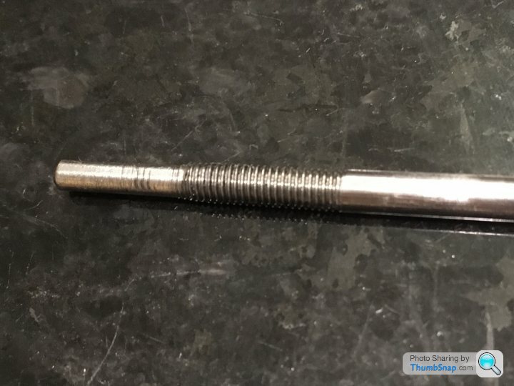
                              M3 has a root diameter of 2.46mm (too small) and a slightly finer pitch Than 5BA. I had an old M3 die which did, for whatever reason, fit over the spigot, but the thread was all over the place. A new M3 die wouldn’t fit at all. The rod also got slightly bent during all this. It does fit, and it does slide in the chest, but it’s not right at all – too sloppy, and the end got damaged by the die:

                              So…I don’t want to re-make another valve chest because it fits everything else perfectly. The only option I can see is to drill the top chest hole out to 1/8” (same as the reamed gland hole at the bottom), Loctite a brass plug into it and re-drill to 3/32”. That would effectively leave me with a 0.4mm wall thickness sleeve in the top end.
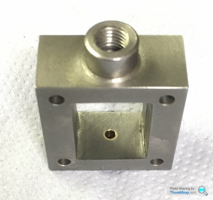
                              And of course I'd re-make the rod from scratch.

                              I could do with some advice on turning small diameter rods in silver steel/stainless. I've never been able to do it properly. In this case, I had to leave enough protruding from the chuck so I could remove the tail centre and keep test fitting it in the valve block, which is relatively deep. I'll need to nail a technicque for doing them for other critical parts that are on the horizon.

                              If I do have to buy another valve chest casting and start again, I will do, but I'd really, really prefer not to.

                              Thanks!

                              #487031
                              JasonB
                              Moderator
                                @jasonb

                                As you won't get a full depth of thread on the reduced diameter guide more a flat rod with a spiral groove I doubt it will make any difference to the running of the engine so you can make it to fit the hole then run the die down the lot.

                                You did not say if you reduced the shaft to 3mm before cutting the M3 thread if not that could explain it being wonky and an old die will always struggle in stainless.

                                Your biggest issue at the moment is the wayward thread as it may twist the valve nut and cause it to lift off the port face but that will depend to some extent how tight the valve nut thread is. ideally make a new rod same size to fit the end hole and thread 5BA as it is easier to do that now rather than having to mount the piston onto a replacement rod.

                                Use one of your DCGT inserts on the stainless and in fact on any long slender work, your holding and tailstock support is fine.

                                #487039
                                Dr_GMJN
                                Participant
                                  @dr_gmjn

                                  Thanks Jason.

                                  I will use the old rod to practice getting a good finish.

                                  I appreciate that a partial depth thread on the spigot end would probably be fine, functionally, but I just don’t like the thought of it being like that. I’d rather make it to size, and get it right.

                                  Apart from time and messing about, can you see any issue with plugging with brass and re-drilling? Apart from having to set-up the block in the 4-jaw again, I think I can get it true to a decent level. As you say, the gland seal seems to do most of the alignment, and the spigot just stops any major wobble.

                                  Thanks.

                                  #487052
                                  Martin Connelly
                                  Participant
                                    @martinconnelly55370

                                    Have you got a travelling steady? It helps with some jobs on long slender parts where only the end needs machining but it is not being done close to the chuck. Even a lashed up steady will help, it doesn't have to be pretty (I haven't got one but I think the Smart & Brown one is an ugly lump).

                                    Martin C

                                    #487060
                                    Dr_GMJN
                                    Participant
                                      @dr_gmjn
                                      Posted by Martin Connelly on 22/07/2020 09:31:40:

                                      Have you got a travelling steady? It helps with some jobs on long slender parts where only the end needs machining but it is not being done close to the chuck. Even a lashed up steady will help, it doesn't have to be pretty (I haven't got one but I think the Smart & Brown one is an ugly lump).

                                      Martin C

                                      I do have a Myford one yes. I've only used it once (came in a box when I bought the lathe). I could give it a go. Thanks.

                                      #487079
                                      JasonB
                                      Moderator
                                        @jasonb

                                        As you have things lined up already with the existing hole you could just loctite a sleeve into the hole. Make it a bit smaller say 1.8mm ID so it has some strength and turn the end of the rod down to suit.

                                        #487090
                                        Dr_GMJN
                                        Participant
                                          @dr_gmjn
                                          Posted by JasonB on 22/07/2020 13:05:06:

                                          As you have things lined up already with the existing hole you could just loctite a sleeve into the hole. Make it a bit smaller say 1.8mm ID so it has some strength and turn the end of the rod down to suit.

                                          There's an idea.

                                          I've got a load of brass tube for modelling. I wonder if some might happen to fit…

                                          Anyway it looks like this evening's entertainment is arranged. I have *just* enough rod spare to try once more. No room for error though.

                                          #487091
                                          Ramon Wilson
                                          Participant
                                            @ramonwilson3

                                            Hi Dr G, still following your progress.


                                            Just a thought you might like to consider on the valve rod set up.

                                            Instead of threading the rod and valve nut just have a nut that has a small grub screw set into lock the nut in position.

                                            The big advantage of this is that when setting the valve you do not have to keep breaking the valve linkage apart in order to make adjustment by turning the valve rod.

                                            I used this idea which was passed to me by 'KBC' over on MEM when rebuilding my ST twin. It works really well, does not slip and has simplified valve setting no end. I pass it on in the same spirit that George did


                                            Regards – Ramon

                                            Edited By Ramon Wilson on 22/07/2020 15:06:19

                                            #487169
                                            Dr_GMJN
                                            Participant
                                              @dr_gmjn
                                              Posted by Ramon Wilson on 22/07/2020 15:05:33:

                                              Hi Dr G, still following your progress.

                                              Just a thought you might like to consider on the valve rod set up.

                                              Instead of threading the rod and valve nut just have a nut that has a small grub screw set into lock the nut in position.

                                              The big advantage of this is that when setting the valve you do not have to keep breaking the valve linkage apart in order to make adjustment by turning the valve rod.

                                              I used this idea which was passed to me by 'KBC' over on MEM when rebuilding my ST twin. It works really well, does not slip and has simplified valve setting no end. I pass it on in the same spirit that George did

                                              Regards – Ramon

                                              Edited By Ramon Wilson on 22/07/2020 15:06:19

                                              Thanks Ramon, that's a very neat idea. I wish I'd have heard of it before trying to thread the un-threadable.

                                              I only just read your post, and have spent this evening trying to correct the valve chest hole (outlined below). If I have further issues with the thread, I'll use your grub screw method. Thanks very much.

                                              #487170
                                              Dr_GMJN
                                              Participant
                                                @dr_gmjn

                                                So I tried to find a sleeve of about the right size, but no luck. I also considered making a Pre-drilled bush to press in, and drill to size when fitted, but a) A small enough drill was very flexible and b) The very thin wall might collapse on fitting.

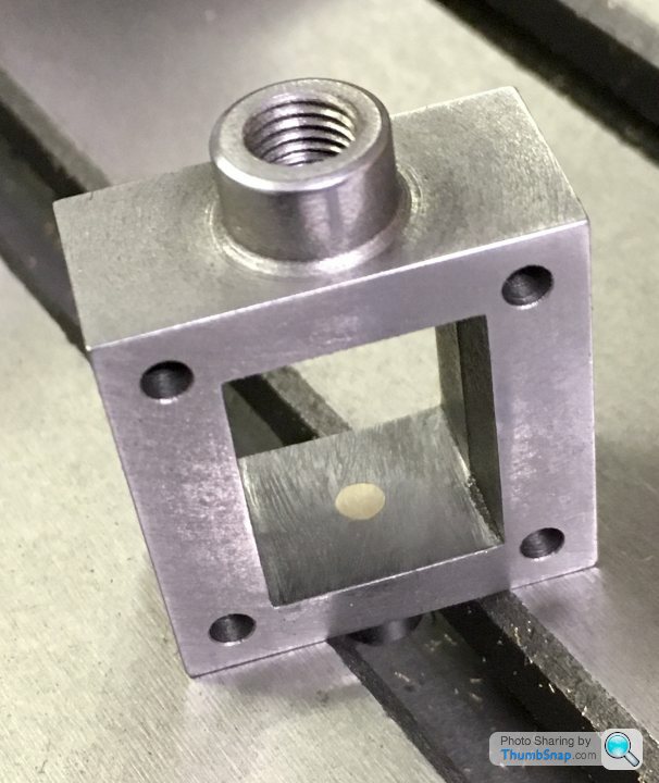
                                                Anyway I fitted a plain brass plug:

                                                Set it up as best I could again in the 4-jaw chuck and re-drilled to a size that was a definite clearance fit in the 5BA die:

                                                OK, ok it’s not drilled exactly centrally, but there we go. I guess there was no guarantee the initial hole was spot-on either.

                                                There is some float in the lower seal hole and nut, so I think the new valve rod (yet to re-make it) should be a good enough fit. If not I’ll drill out again and risk a pre-centred bush.

                                                Anyway, lessons learned. Onwards…

                                                #487197
                                                Dr_GMJN
                                                Participant
                                                  @dr_gmjn

                                                  Presumably the 3.1mm diameter valve rod is a suitable diameter for a 5BA thread?

                                                  From what I can find, the O/D on a 5BA thread should be 3.2mm, so a 0.1mm undersize should be safe in terms of threading (but maybe a bit sloppy?

                                                  Cheers.

                                                  #487200
                                                  Mick B1
                                                  Participant
                                                    @mickb1
                                                    Posted by Dr_GMJN on 23/07/2020 08:55:40:

                                                    Presumably the 3.1mm diameter valve rod is a suitable diameter for a 5BA thread?

                                                    From what I can find, the O/D on a 5BA thread should be 3.2mm, so a 0.1mm undersize should be safe in terms of threading (but maybe a bit sloppy?

                                                    Cheers.

                                                    The fit of the flanks matters more than the o/d. 3,1 should be fine. With a normal split die you can adjust how much you tighten down the two screws that bear on the free ends of the arc, in tandem with the centre screw that opposes them. start with the die slightly open, test the result, then tighten it down if necessary by a few degrees turn on the screws, and test again till you get a light friction fit. But if you go a little too far, a bit of slop's unlikely to affect function.

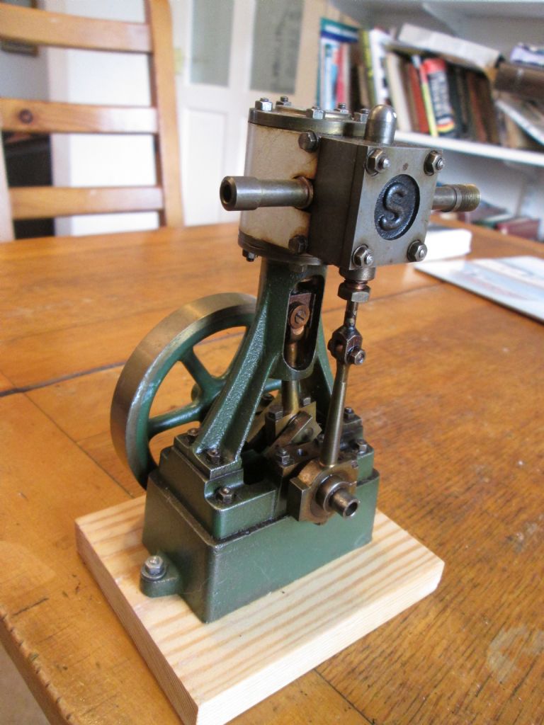
                                                    My 10V's a crude job in comparison with yours, but it's worked very nicely for 25 years.

                                                    Stuart 10V.jpg

                                                    Edited By Mick B1 on 23/07/2020 09:21:42

                                                    #487201
                                                    Dr_GMJN
                                                    Participant
                                                      @dr_gmjn
                                                      Posted by Mick B1 on 23/07/2020 09:16:59:

                                                      Posted by Dr_GMJN on 23/07/2020 08:55:40:

                                                      Presumably the 3.1mm diameter valve rod is a suitable diameter for a 5BA thread?

                                                      From what I can find, the O/D on a 5BA thread should be 3.2mm, so a 0.1mm undersize should be safe in terms of threading (but maybe a bit sloppy?

                                                      Cheers.

                                                      The fit of the flanks matters more than the o/d. 3,1 should be fine. With a normal split die you can adjust how much you tighten down the two screws that bear on the free ends of the arc, in tandem with the centre screw that opposes them. start with the die slightly open, test the result, then tighten it down if necessary by a few degrees turn on the screws, and test again till you get a light friction fit. But if you go a little too far, a bit of slop's unlikely to affect function.

                                                      My 10V's a crude job in comparison with yours, but it's worked very nicely for 25 years.

                                                      Stuart 10V.jpg

                                                      Edited By Mick B1 on 23/07/2020 09:21:42

                                                      Thanks Mick – I'll do that with the die.

                                                      Your 10V looks fine to me, I'd be more than happy with that, the main thing is that it runs well.

                                                    Viewing 25 posts - 201 through 225 (of 385 total)
                                                    • Please log in to reply to this topic. Registering is free and easy using the links on the menu at the top of this page.

                                                    Advert

                                                    Latest Replies

                                                    Viewing 25 topics - 1 through 25 (of 25 total)
                                                    Viewing 25 topics - 1 through 25 (of 25 total)

                                                    View full reply list.

                                                    Advert

                                                    Newsletter Sign-up