Stuart 10V Build Log – Complete Beginner…

Advert

Stuart 10V Build Log – Complete Beginner…

Home Forums Work In Progress and completed items Stuart 10V Build Log – Complete Beginner…

Viewing 25 posts - 151 through 175 (of 385 total)
  • Author
    Posts
  • #480396
    JasonB
    Moderator
      @jasonb

      As you have a DRO I would drill each part individually, set your rear vice jaw true to the Y axis than all parts held against that will also be true. Find ctr of part by touching each edge and then halve the reading or use 1/2 function if a full blown DRO and set out your holes from the centre.

      Same when it comes to the end covers, locate bore and use DRO to place holes in each part in turn.

      Advert
      #480437
      Dr_GMJN
      Participant
        @dr_gmjn

        OK I'll try the DRO method.

        What's the best way of determining the centre of circular parts, such as the cylinder covers, for drilling?

        My thoughts were to secure in the vice, find the inner edges of the vice jaws, and get the "y" centreline from half that distance, then, when centred in "y", touch the edge finder on both sides of the part in the "x" direction, and again half that distance to get the "x" centreline.

        Not sure of the best way to find the centre of the cylinder bore for co-ordinate drilling of the cylinder faces though?

        Any advice appreciated. Thanks.

        #480452
        Anonymous

          Posted by Dr_GMJN on 17/06/2020 10:17:51:

          Not sure of the best way to find the centre of the cylinder bore…………

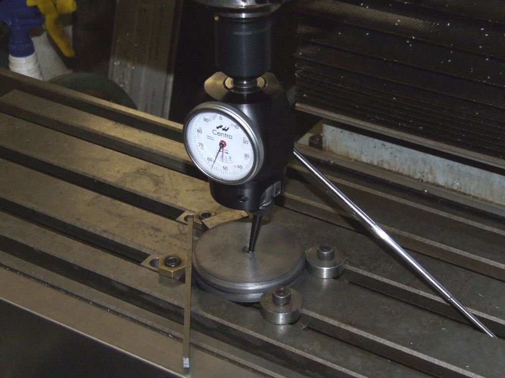
          Osborne's maneuver as detailed in "The Machinist's Second Bedside Reader" by Guy Lautard. Or just pick up on each side of the circle in X and then Y and use the 1/2 function on the DRO at each step to get the centre. Once at the centre a sanity check is to touch off plus and minus X and Y; the readings should be the same. Or, for the lazy, you can use a co-axial indiccator:

          centro_using.jpg

          Andrew

          #480461
          Dr_GMJN
          Participant
            @dr_gmjn

            Thanks Andrew – my DROs are just that, not sure what a 1/2 function is?

            #480465
            Martin Connelly
            Participant
              @martinconnelly55370

              1/2 function divides the selected axis by 2. So if you have an edge finder find the edge on one side set that axis to zero, move the edge finder to the opposite side and find the edge and then divide by 2 using the 1/2 function. The axis zero should now be on the centre line. Repeat for the axis at 90 degrees on the centre line of the first axis. Then for a circular part I go back and repeat the first axis again on the centre line set on the second axis. Easier done than said.

              Martin C

              The requirement for doing this on a centre line for the second axis is for circular parts, not for rectangular parts. I should have been clearer in the initial post.

              Edited By Martin Connelly on 17/06/2020 11:58:30

              #480469
              Dr_GMJN
              Participant
                @dr_gmjn
                Posted by Martin Connelly on 17/06/2020 11:55:25:

                1/2 function divides the selected axis by 2. So if you have an edge finder find the edge on one side set that axis to zero, move the edge finder to the opposite side and find the edge and then divide by 2 using the 1/2 function. The axis zero should now be on the centre line. Repeat for the axis at 90 degrees on the centre line of the first axis. Then for a circular part I go back and repeat the first axis again on the centre line set on the second axis. Easier done than said.

                Martin C

                The requirement for doing this on a centre line for the second axis is for circular parts, not for rectangular parts. I should have been clearer in the initial post.

                Edited By Martin Connelly on 17/06/2020 11:58:30

                Thanks Martin, that's basically what I've been doing for rectangular parts, but just dividing my readout by 2, moving the head to that value, and zeroing it.

                I don't understand about it not applying to rectangular parts – if I want to get 0,0 in the middle, then I'd have to find two centrelines (x & y), and re-zero the head in the middle of the part as above?

                #480475
                JasonB
                Moderator
                  @jasonb

                  The first two readings say -x and +x will probably not be taken across the diameter of the circular part. When you have halved the reading to X=zero you can then touch the two points in the Y axis which will be the diameter, If fussy you can then set the Y=zero and redo the x ctr position again but I seldom find it is needed.

                  Yes if your circular part is held in avice preventing you from touching teh far and near edge then you can use the vice jaws.

                  From your comments I assume you have just a basic scale on each axis with a readout, the more complex units have the half function along with many others.

                  #480493
                  Ron Laden
                  Participant
                    @ronladen17547

                    I tend to use the test indicator now to find the centre on round parts both internal and external, quite quick to do and accurate.

                    #480529
                    Dr_GMJN
                    Participant
                      @dr_gmjn

                      Ok thanks guys. I think I can have a decent go at it then.

                      re. The thin cylinder caps: I need to turn, drill and thread a boss, then part off, turn around and turn a shallow locating boss. I was thinking of boring a hole in some stock on the lathe, then pressing the finished half of the cover into it, then finishing the face. Will this work, or will the part need more positive location to stop it moving? The features need to be Perfectly concentric one side to the other?

                      Thanks.

                      #480533
                      JasonB
                      Moderator
                        @jasonb

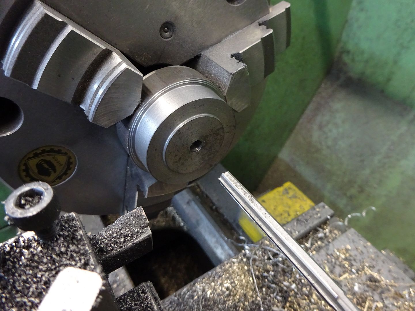
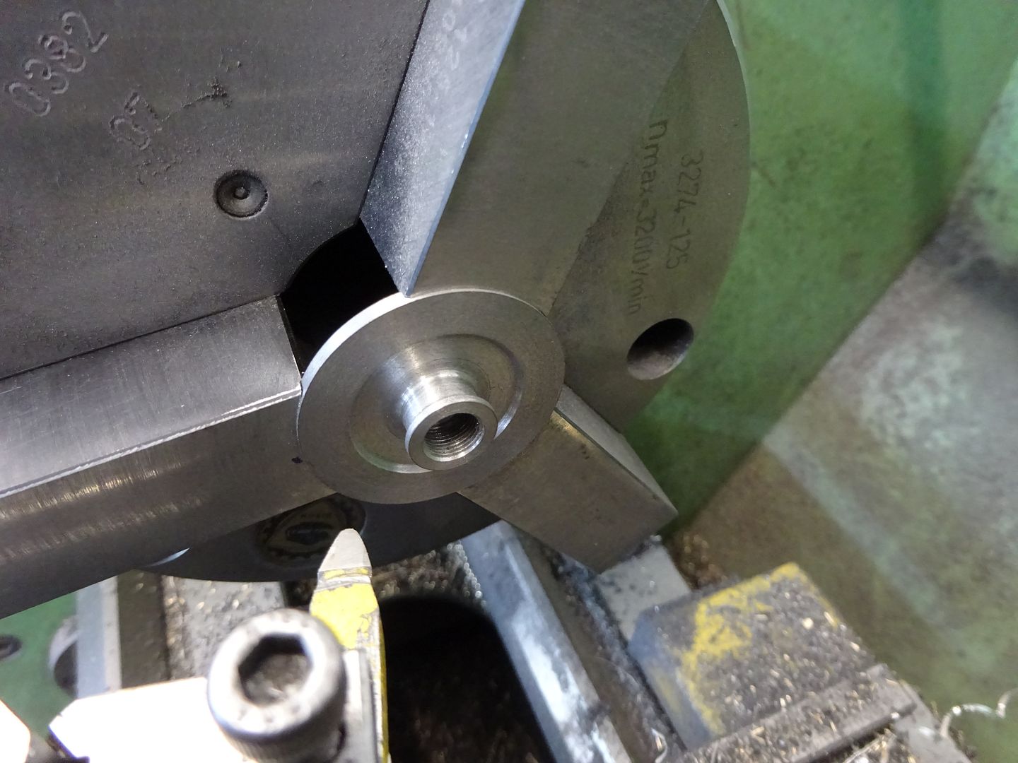
                        I would come at it from the other side turning the shallow spigot and reaming the piston rod hole at one setting as they are what need to be the most concentric. You can then reverse to do the exposed side and tap for the gland nut, when threading the nut tighten the die up so there is a little play in the threads then it will be able to float a bit and ctr itself on the piston rod.

                        I like to use my soft jaws for jobs like these not only will they give the concentricity they also give a solid edge to push thing work back against

                        First setting

                        second

                        Edited By JasonB on 17/06/2020 16:48:17

                        #480536
                        Martin Connelly
                        Participant
                          @martinconnelly55370

                          For small round parts I clamp a small chuck to the mill to hold them. A parallel support can be used without worrying about it flying out since the chuck is not spinning. I have a 100mm chuck mounted to a plate to make it easy to clamp without interfering with the top of the chuck. A lot of people with rotary tables mount their chucks on a Morse taper that fits in the RT.

                          Martin C

                          #480602
                          Dr_GMJN
                          Participant
                            @dr_gmjn

                            OK guys I'll have a think about it. I don't have a rotary table, and I don't trust my three jaw chuck.

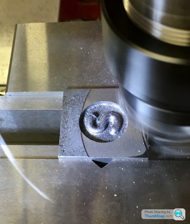
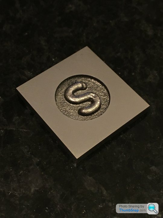
                            Anyway, I didn’t have much time this evening, so I just squared and flatted the valve chest cover. First job was to mill the edges; first opposite pair I face-milled vertically, then clamped those faces horizontally and side-milled the other two. I made sure the “S” Circle was central:

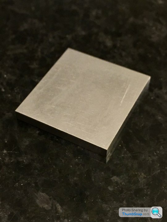
                            Then fly-cut the faces to the right thickness:

                            The finish using the power feed is really nice – the leading cut obviously takes the majority of the material off, and the trailing cut just skims the surface. I think this must mean that my tramming efforts weren’t so bad after all. I finished by lightly rubbing on wet and dry on the surface plate:

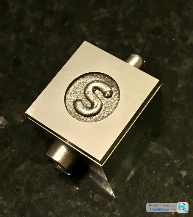
                            It’s a shame that to *just* completely clean up the side edges, it went undersize. I’ve tried to make the gap equal all around. Not to plan, but there was no way around it I could think of:

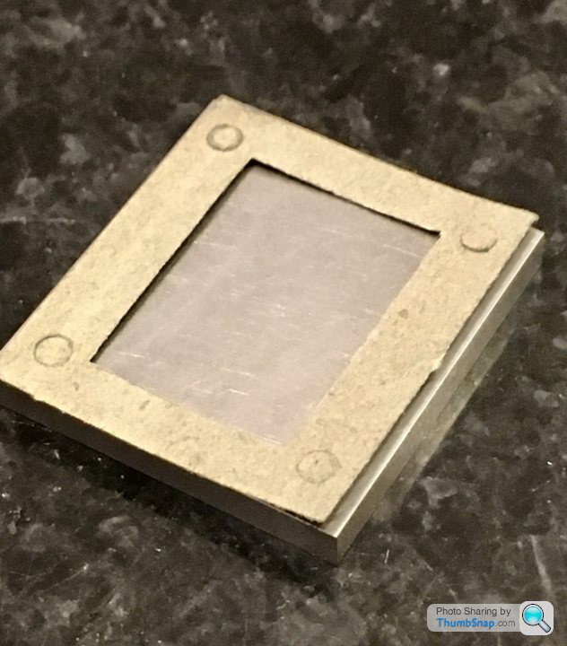
                            If Im careful, I can get the cover to stick to the chest on its own:

                            The gasket is not a great fit, and I suppose I may have to re-position the holes very slightly, but it shouldn’t be a big issue.

                            I’ll try to get the cylinder caps done next, then spend the weekend’s workshop time drilling all the mounting holes. I think calculation of all the co-ordinates will be at least a two-mug-of-tea job.

                            #480606
                            Mick B1
                            Participant
                              @mickb1
                              Posted by Dr_GMJN on 17/06/2020 21:56:45:


                              I’ll try to get the cylinder caps done next, then spend the weekend’s workshop time drilling all the mounting holes. I think calculation of all the co-ordinates will be at least a two-mug-of-tea job.

                              IIRC the calc's on the back of the Zeus booklet. I made my top end cap out of phosphor bronze – I thought it might look nicer. It did for a year or three – now it looks like lightly-rusted steel. But the phosphor bronze tyre I shrink-fitted on the flywheel still looks good.

                              #480659
                              Dr_GMJN
                              Participant
                                @dr_gmjn
                                Posted by Mick B1 on 17/06/2020 22:55:33:

                                Posted by Dr_GMJN on 17/06/2020 21:56:45:


                                I’ll try to get the cylinder caps done next, then spend the weekend’s workshop time drilling all the mounting holes. I think calculation of all the co-ordinates will be at least a two-mug-of-tea job.

                                IIRC the calc's on the back of the Zeus booklet. I made my top end cap out of phosphor bronze – I thought it might look nicer. It did for a year or three – now it looks like lightly-rusted steel. But the phosphor bronze tyre I shrink-fitted on the flywheel still looks good.

                                Thanks, yes, I used the booklet to get the co-ordinates for the motor mount plate PCD holes.

                                The valve cover plate will need to be re-calculated because of it's smaller size, or at least they need carefully checking.

                                #480663
                                Dr_GMJN
                                Participant
                                  @dr_gmjn

                                  I notice there is no oil hole for lubricating the big end on this model, yet there is one for the eccentric.

                                  This seems like a potential issue – are there any neat ways of incorporating a method of lubricating the big end?

                                  I was also told that the cylinder drain cocks aren't needed, becasue the floating valve allows excess condensed water out. Not sure how, just asking the question. The drain cocks commonly used do look a bit over-sized. Any comments?

                                  Also, for the steam inlet and exhaust, can anyone recommend some neat looking brass fittings? I'd like to fit a short exhaust stub – perhaps some thin walled brass tube, and a connection for compressed air. Ideally the pipe connector for the air would be removable for display, perhaps just leaving a threaded or plain bore fitting. I don't want to drill the holes before having the fittings.

                                  Thanks.

                                  #480668
                                  Martin Connelly
                                  Participant
                                    @martinconnelly55370

                                    Think of them as pre-heating vents rather than as drains. You can allow steam to flow through and get everything hot before running so there will be minimal condensate in the cylinders when first run. It's probably important on a large scale steam engines, not so much on a model that is not really required to be a working engine.

                                    You can make your own brass fittings for pipework quite easily. Solder a small ring on the outside diameter near the end of the tube for retention of the tube. Thread the end of a piece of hexagonal brass and drill through for the tube OD and part off the hex bar. If required you can also recess the nut to suit the retaining ring outside diameter. P

                                    Martin C

                                    #480699
                                    JasonB
                                    Moderator
                                      @jasonb

                                      For air you also need to think about how you will control the volume particularly if your compressor does not have a pressure regulator.

                                      I use the push fit fittings for PVC pipe and depending on size of engine will use 4, 6 or 8mm OD pipe. You can either tap the chest and exhaust to take one of these fittings or tap to take a short stubby length of tube and use a double ended connector to push over the metal stub, tube could simply be a rod with hole drilled. Other end of PVC pipe goes to a suitable push fit connector that has a thread to suit your compressor usually 1/* or 1/4 BSP. If you intend to run several engine sthen you can make a manifold.

                                      Failing that a simple fitting can be turned up with a barbed end to push a bit of tube on and flow "adjusted" by kinking the tube

                                      #480703
                                      Martin Connelly
                                      Participant
                                        @martinconnelly55370

                                        Kinking the tube is not very engineery. mole grips are far more impressivewink

                                        Martin C

                                        #480705
                                        Roderick Jenkins
                                        Participant
                                          @roderickjenkins93242

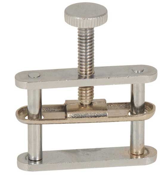
                                          Those of us from a sciency background would use a tube clamp:

                                          tube clamp.jpg

                                          Rod

                                          #480747
                                          Dr_GMJN
                                          Participant
                                            @dr_gmjn

                                            Thanks for the ideas all.

                                            I've got a compressor and regulator, and a cut-off tap at the end of the pipe. I use it mainly for airbrushing, so need a controlled supply.

                                            #480937
                                            Dr_GMJN
                                            Participant
                                              @dr_gmjn

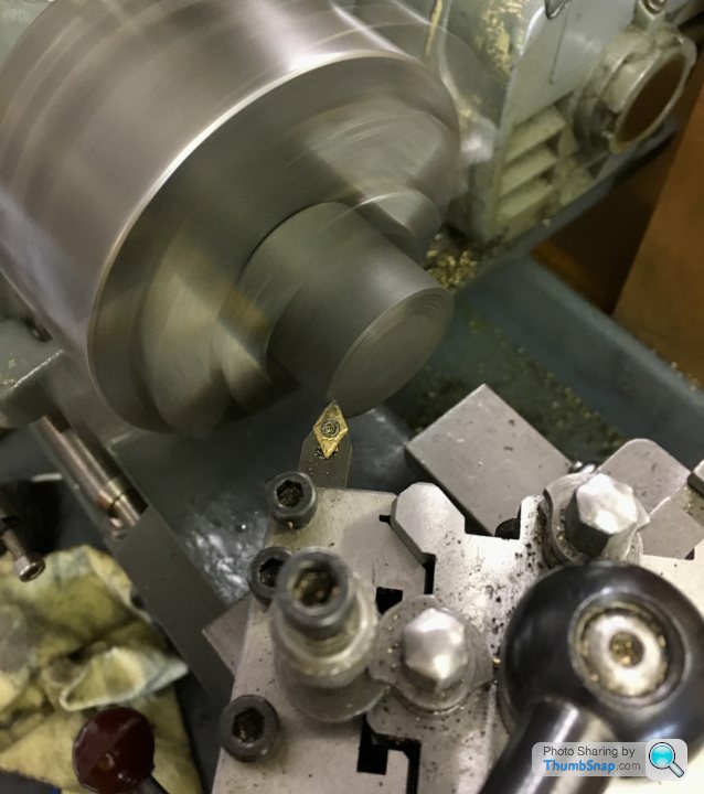
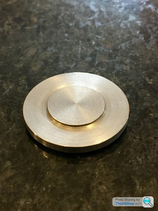
                                              So I made a start on the cylinder covers, firstly the top one, because It’s much less critical than the lower. The only feature that’s important is the spigot that fits into the cylinder.

                                              I chucked the cast iron bar in the three jaw, faced and turned to size:

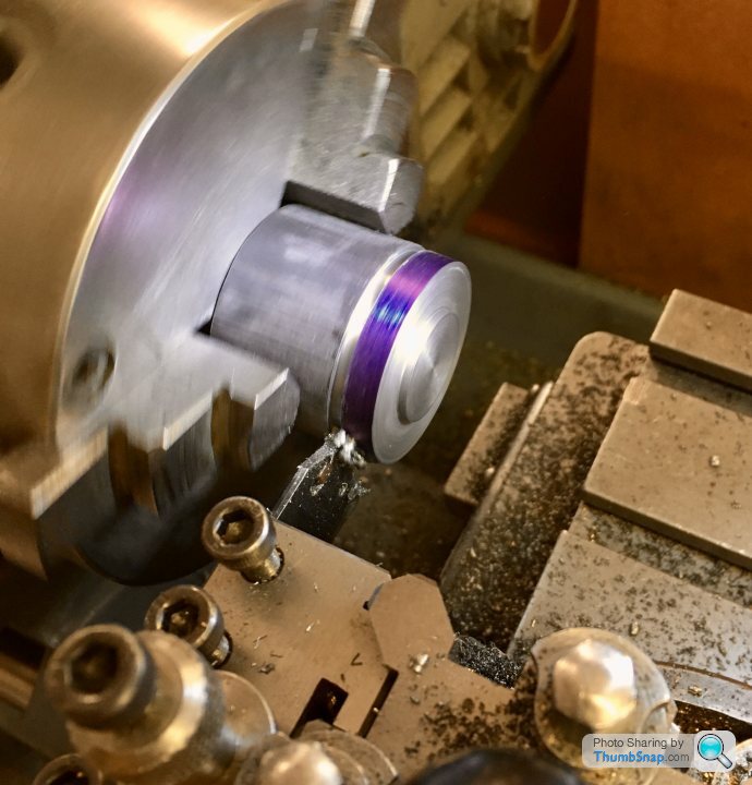
                                              Then turned the inner spigot, to be a good fit in the bore diameter:

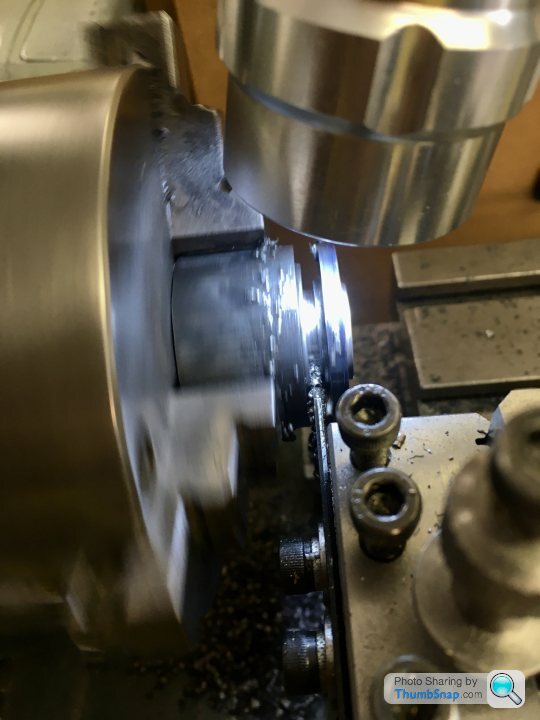
                                              I started to part-off the job, with the intention of reversing it in the chuck and turning the top features. It seemed to be going well, so I decided to part it in two stages- the first to form the upper boss, then move the tool back and part off from the stock:

                                              It actually worked pretty well, but some clean-up was required anyway, and due to this the top boss is a bit short (not that it matters). On balance I should have parted off long, reversed and just turned the other side as normal. In the end my initial method could have worked, but as usual didn’t quite.

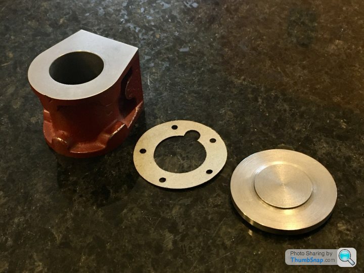
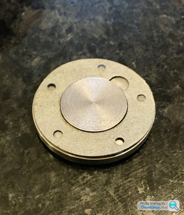
                                              Anyway, it fits the cylinder, and it’s gasket, and it looks ok:

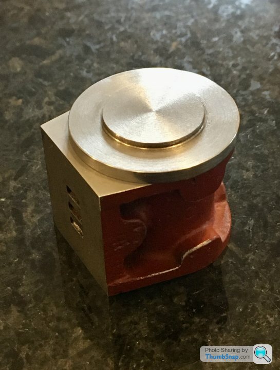
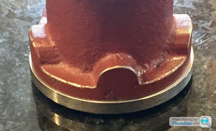
                                              I was hoping the overhang would be concentric around the circular portion, so the lagging plate would be a flush fit. Unfortunately it’s not the case:

                                              So some filing will be needed. Pretty sure I set up the casting pretty much as good as it could have been, so I wonder if the cast surface is slightly bulged? No big deal.

                                              So next the lower cover. I still don’t really know how to reverse and hold it. I don't have soft jaws, and the three jaw chuck isn't great (it didn't matter for the top cover). I'm still wondering if turning a socket in some brass to a press-fit around the gland boss would do, then superglue the half machined cover onto it. If I used my previous double parting off method, then I'd only be cleaning up the face, spigot diameter and depth using very light cuts. All the drilling, tapping and reaming would have been done on the other side already.

                                              Edited By Dr_GMJN on 19/06/2020 17:52:36

                                              #480942
                                              JasonB
                                              Moderator
                                                @jasonb

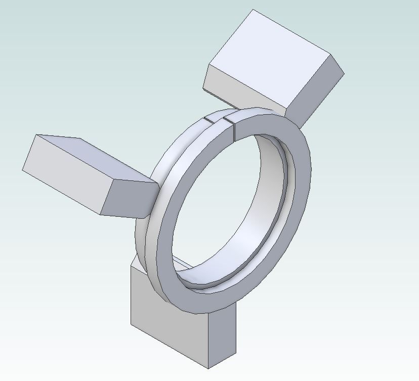
                                                Another option is to make a split bush. Take a short length of stock about 6mm larger diameter than the cover and turn a spigot on the end about 5mm long. Reverse the bush in the chuck so that you are now gripping by the spigot and the larger dia is pushed back against the front of the jaws. Bore right through a couple of mm less than cover diameter and then for about 2mm deep open up to a snug fit on the cover's outer edge.

                                                Mark the bush in some way so it goes back into the chuck in the same position before removing and cutting a slot right through it. You can now slip the cover into the recess, put bush into chuck and pushing both back against jaws and step in the bush tighten the chuck.

                                                As the recess was turned it will be concentric so provided you put it back in the same position the hole will remain concentric and therefore hold the cover concentric and as the back of the cover has something to register against it won't wobble either.

                                                spli bush.jpg

                                                #480983
                                                Dr_GMJN
                                                Participant
                                                  @dr_gmjn
                                                  Posted by JasonB on 19/06/2020 18:37:03:

                                                  Another option is to make a split bush. Take a short length of stock about 6mm larger diameter than the cover and turn a spigot on the end about 5mm long. Reverse the bush in the chuck so that you are now gripping by the spigot and the larger dia is pushed back against the front of the jaws. Bore right through a couple of mm less than cover diameter and then for about 2mm deep open up to a snug fit on the cover's outer edge.

                                                  Mark the bush in some way so it goes back into the chuck in the same position before removing and cutting a slot right through it. You can now slip the cover into the recess, put bush into chuck and pushing both back against jaws and step in the bush tighten the chuck.

                                                  As the recess was turned it will be concentric so provided you put it back in the same position the hole will remain concentric and therefore hold the cover concentric and as the back of the cover has something to register against it won't wobble either.

                                                  spli bush.jpg

                                                  I did think of something like that – but my thinking was as soon as I removed it from the chuck, the precise concentricity might be lost. If it works, I am much happier making that, than the other methods.

                                                  I suppose I could check concentricity by putting my dial gauge on the outer diameter of the fixture ring? Combined with the the undersized thread…I think this might actually get done this weekend after all.

                                                  BTW, At some point very soon I'll be drilling all the holes for these components. Some of them have good surface finishes – is it acceptable to put paper between these surfaces and the vice jaws for protection, or shouldn't it matter too much becasue of the polished finish on the jaws?

                                                  Cheers!

                                                  Edited By Dr_GMJN on 19/06/2020 21:08:51

                                                  #481009
                                                  JasonB
                                                  Moderator
                                                    @jasonb

                                                    Should not matter as machine vice jaws are smooth so won't mark like a bench vice. Just make sure they are clean of swarf.

                                                    #481015
                                                    Danny M2Z
                                                    Participant
                                                      @dannym2z

                                                      For a beginner this is an excellent build log.

                                                      Thank you very much for posing all the details Dr_GMJN

                                                      BTW, I often use a slip of paper between vice jaws and the work. Not so much to protect the finish though as it really improves the grip between the components

                                                      * Danny M *

                                                    Viewing 25 posts - 151 through 175 (of 385 total)
                                                    • Please log in to reply to this topic. Registering is free and easy using the links on the menu at the top of this page.

                                                    Advert

                                                    Latest Replies

                                                    Viewing 25 topics - 1 through 25 (of 25 total)
                                                    Viewing 25 topics - 1 through 25 (of 25 total)

                                                    View full reply list.

                                                    Advert

                                                    Newsletter Sign-up