Stuart 10V Build Log – Complete Beginner…

Advert

Stuart 10V Build Log – Complete Beginner…

Home Forums Work In Progress and completed items Stuart 10V Build Log – Complete Beginner…

Viewing 25 posts - 126 through 150 (of 385 total)
  • Author
    Posts
  • #478579
    Dr_GMJN
    Participant
      @dr_gmjn

      Thanks both. I’m pretty sure a cutter will be able to make a better job of it than me with a hacksaw – never could saw square.
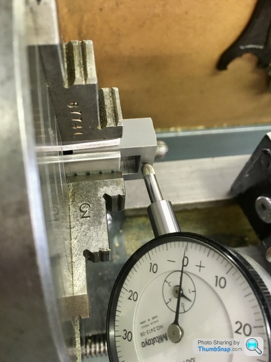
      Fly cutting the faces might be a tall order – they’re tiny. Maybe milling would be ok though?

      cheers.

      Advert
      #479895
      Dr_GMJN
      Participant
        @dr_gmjn

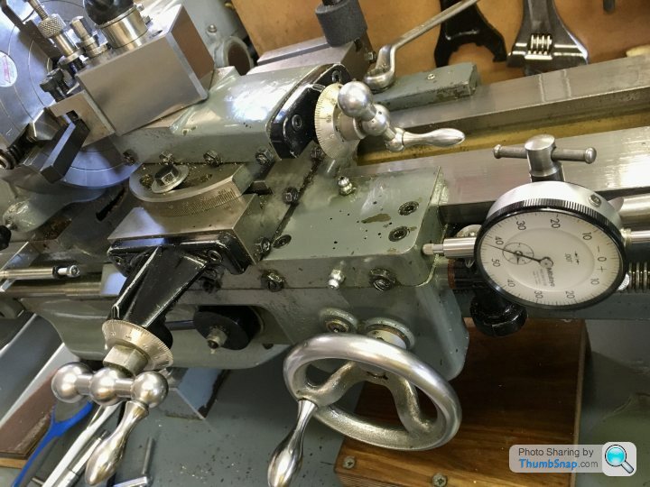
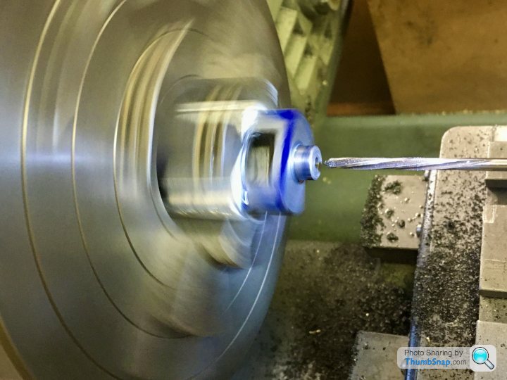
        Got a bit distracted again last week, this time adding a motor to the x-feed screw. I found a ‘how to’ online, and half followed it – it's a much simplified version, but it'll do what I need it to.

        First job was to extend the lead screw and cross-drill it for a drive pin:

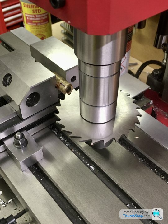
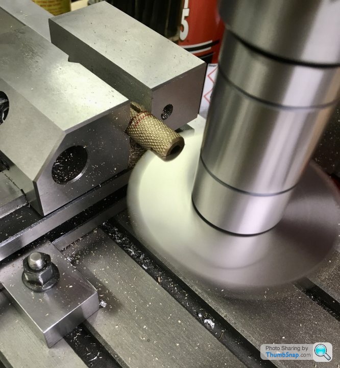
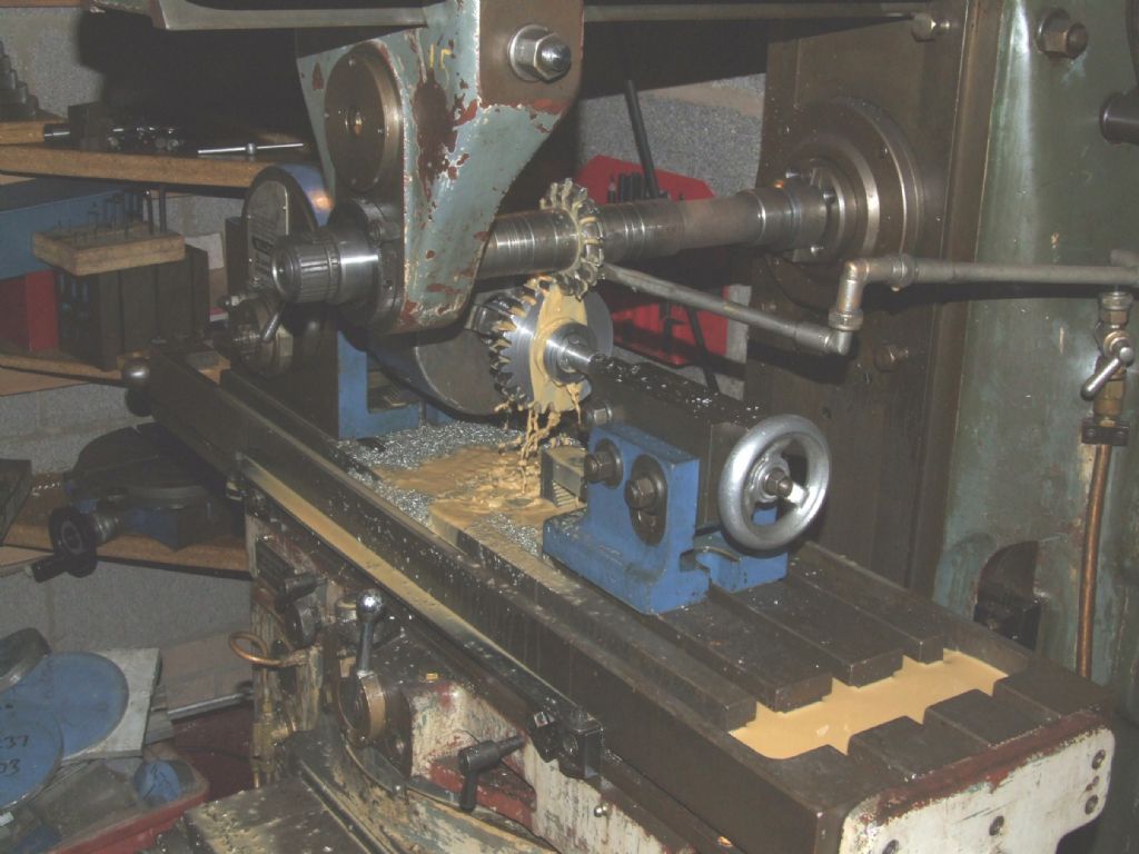
        A simple dog clutch is made from a piece of brass, turned, knurled and slotted at both ends with a “what could possibly go wrong?” slitting saw:

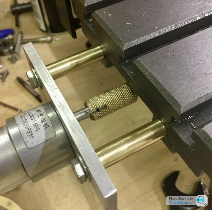
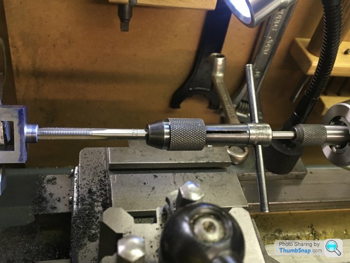
        Then drill and tap the end of the bed to take some bolts and spacers for a motor plate:

        It’s a 12v geared motor. I’ll be running it through a 15v PWM speed controller. Obviously still needs a casing and control panel, but it seems to work ok on a 15v laptop charger.

        Edited By Dr_GMJN on 14/06/2020 21:45:49

        #479900
        Dr_GMJN
        Participant
          @dr_gmjn

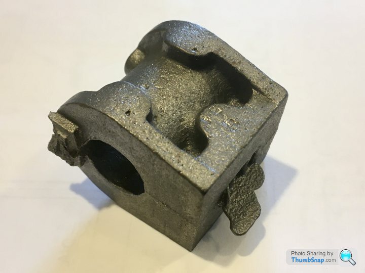
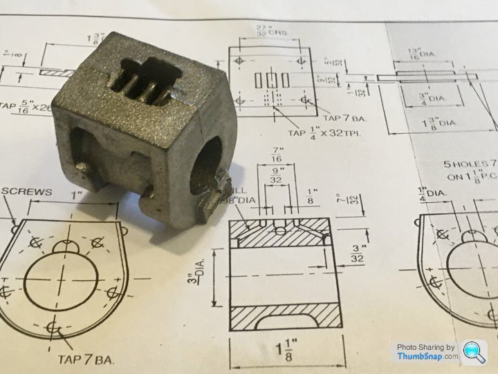
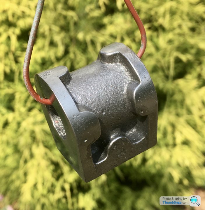
          So on to one of the critical bits: the cylinder. The black casting is a bit rough:

          The drawings have the minimum information, un-toleranced (luckily):

          Started by cleaning up the outside by filing:

          And painted with red oxide so I can see what’s what.

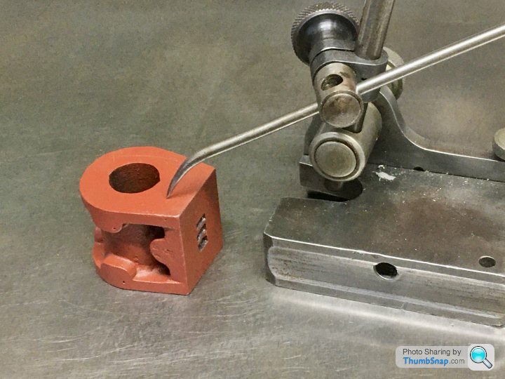
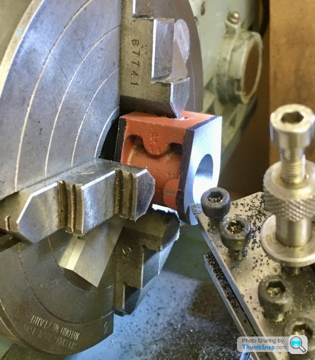
          After looking at online builds and my 10V book, it seems like there are many ways to machine this part. I went with what I understood, and what I thought was easiest. I’m not sure it’s worked out, but more on that later. I scribed my best fit line around one end from the surface, using callipers. Then did a quick check to see if everything was about the right height all around:

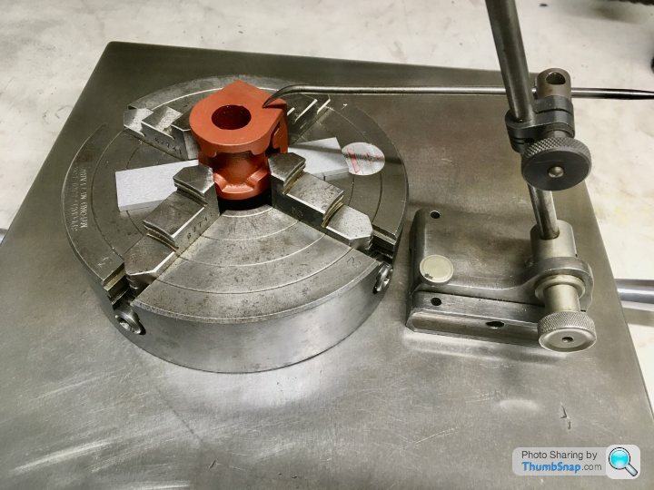
          Double checked with it in the chuck. I put a parallel behind it to make it as square as a filed casting face would allow:

          Then clocked it up to the best fit around the cast circular flange. I did this rather than the bore because there needs to be a constant depth step around here for the insulation plate, defined by the cylinder caps:

          And checked the filed face was about right:

          Bored the…bore:

          Faced:

          Then removed and marked out using callipers for the length. I also scribed “B” on the casting so I know this is the lower end and everything is perpendicular (hopefully):

          Re-fitted in the chuck using a parallel to seat the machine face on:

          #479902
          Dr_GMJN
          Participant
            @dr_gmjn

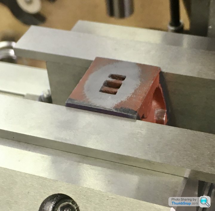
            I thought about the next operation a lot, but it seemed like alignment by eye was as good as anything. I calculated the bore-face dimension using my bore size, and calculated how much to remove from the cast/filed face. I then scribed a line from the face using callipers. I put the cylinder in the vice and eyeballed the level using a parallel and slip gauge to form a datum plane. This was done both sides as a check, and it seemed to match:

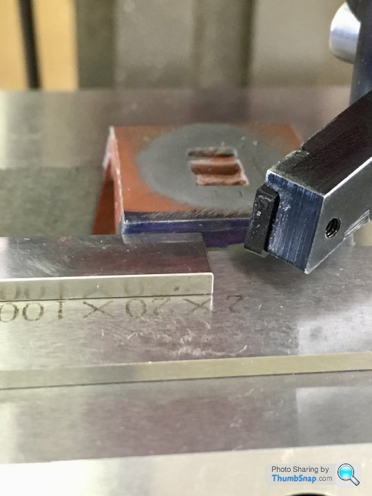
            I used the parallel/gauge to set the fly cutter to zero on the DRO for depth:

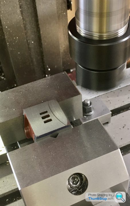
            Then fly cut the face using my new x-axis power feed:

            I’m happy with the finish:

            I balanced everything together and it seems to be square:

            However, despite the cast flanges being equal depth to within about 0.15mm (the book advises to aim to get these the same), the port-face distances aren’t equal, there being about a 0.5mm discrepancy:

            I think I can compensate for this error by adjusting the slide valve on its rod.

            Also, the faces aren’t parallel. I’ve got an approx. 0.17mm difference front/back. This must have been due to me using the chuck face/parallel as a datum somehow. Perhaps I should have made a mandrel. I don’t think it will really matter so long as the first (bottom) face is normal to the bore axis, but it is annoying to get it so wrong.

            #479903
            Dr_GMJN
            Participant
              @dr_gmjn

              So to summarise what I've ended up with in terms of critical dimensions:


              Bore: Drg: 19.05mm, Actual: 19.01mm, d= -0.04mm (-0,002"  )

              Bore Axis to Valve Face – Drg: 19.84mm, Actual: 19.565mm, d= -0.28mm (-0.011"  )

              Average Cylinder Depth – Drg: 28.575mm, Actual: 28.395, d= -0.18mm (-0.007"  )

              Max. Cylinder Depth Error (front/back): 0.17mm (0.007"  )

              Valve Port Face Width – Drg: 25.4mm, Actual: 25.4mm


              Questions:

              1) All things considered, are these figures good/bad/indifferent (bearing in mind there are no tolerances on the drawings)?

              2) Do I need to correct anything?

              3) I tried to machine to my marked-out lines on the casting, because I had no flat datums to touch on to, to use handwheels/DROs. What's the best procedure for this? I can only think to machine a datum, remove form the machine and measure, then re-fit to the machine and cut to depth using the read-outs (at least for parts that I can get access to measure).

              4) Any comments on the methods I used, and how to avoid errors in future are, of course, welcome.


              Next job: steam ports. Thanks!

              Edited By Dr_GMJN on 14/06/2020 22:51:16

              #480002
              JasonB
              Moderator
                @jasonb
                Posted by Dr_GMJN on 14/06/2020 22:23:05:

                Bore: Drg: 19.05mm, Actual: 19.01mm, d= -0.04mm (-0,002" )

                leaves a little for final hone/lap so will be fine, Expect your callipers are reading slightly under anyway

                Bore Axis to Valve Face – Drg: 19.84mm, Actual: 19.565mm, d= -0.28mm (-0.011" )

                Not too critical can be compensated for by altering eccentric so it sits closer to bore axis by skimming a bit off if things bind on final assembly

                Average Cylinder Depth – Drg: 28.575mm, Actual: 28.395, d= -0.18mm (-0.007" )

                Not critical, you could make spigot on top cover shorter bt same amount to compnsate but don't sweat over it

                Max. Cylinder Depth Error (front/back): 0.17mm (0.007" )

                Would be nice to know where that crept in, possibly piston rod face not right back against 4-jaw face when machines, chuck jaws on the casting could have moved it slightly when tightened as would more than likely have contacted one flange before the other. Again should not affect running as you made sure bore and piston rod end where done at the same setting

                Valve Port Face Width – Drg: 25.4mm, Actual: 25.4mm

                Can't complain about that

                Questions:

                1) All things considered, are these figures good/bad/indifferent (bearing in mind there are no tolerances on the drawings)?

                See comments above

                2) Do I need to correct anything?

                Ditto

                3) I tried to machine to my marked-out lines on the casting, because I had no flat datums to touch on to, to use handwheels/DROs. What's the best procedure for this? I can only think to machine a datum, remove form the machine and measure, then re-fit to the machine and cut to depth using the read-outs (at least for parts that I can get access to measure).

                A line will always be a few thou thick and hard to split down the middle. Zeroing DRO after a cut and then taking out to measure what still needs to come off is OK, I do that. If your is resting on a surfac eyou could touch off on that and zero DRO then you know how far beyond that your finish cut needs to be. For cylinder length you could have put carrage against your new stop and touched the tool onto the 4-jaw's face, and then would back the topslide 1 11//8, noted reading and then faced until you got to that reading.

                4) Any comments on the methods I used, and how to avoid errors in future are, of course, welcome.

                Next job: steam ports. Thanks!

                Don't forget to poke some fuse wire down them to remove any remaining core sand

                Edited By Dr_GMJN on 14/06/2020 22:51:16

                #480018
                Dr_GMJN
                Participant
                  @dr_gmjn

                  Thanks Jason, that's all good. I guess the non-parallel cylinder faces were a result of the jaws moving the workpiece. I'm pretty gutted about it, but I'll know to double check the seating next time.

                  Question about lapping:

                  Plain hardwood plug, tight running fit, #600 SiC and oil, run the cylinder along and back with the wood rotating?

                  Same with the standard.

                  But how do I lap the piston to the bore with the #1000 in terms of which bit to hold, and which bit to move, and how to align? Same with the crosshead and standard.

                  How should the initial fit feel?

                  Thanks.

                  #480026
                  JasonB
                  Moderator
                    @jasonb

                    That's it for the cylinder, lap in the lathe & run fairly slowly 100-200 rpm and just work it up and down the wooden lap.

                    Piston, machine it but leave say 5thou over diameter and then mount onto the piston rod. Hold assembly by rod and get that running as true as you can and then take a couple of light skim cuts off the piston trying it into the cylinder after each until is will just enter. you can do the last bit by hand holding by the rod and work the piston into the bore with a tiny amount of 1000g and plenty of oil or it could be done on the lathe. I don't always lap the piston just leave it as the turned finish so upto you.

                    Have a look at my Filer & Stowell thread a bit later and I'll show the cross head being lapped for that

                    #480057
                    Anonymous

                      Out of idle curiosity I thought I'd measure the variation in width on my two recently squared up cylinders. Taking three points on each, one has a maximum variation of 0.1mm and the other is 0.05mm. Of course the variation doesn't matter. What is critical is that the bore is perpendicular to the face that controls piston alignment. What the other face, which is just a cover, does isn't important.

                      Andrew

                      #480067
                      Chris Gunn
                      Participant
                        @chrisgunn36534

                        Hi, if you are worried about the end faces, you could always make a slightly tapered mandrel, and carefully polish the taper on, and taper it so the cylinder goes about 3/4 of the way on, put a bit of thin oil on it, then gently tap the cylinder block on tight while the mandrel is still in the chuck, and then take a skim off the end of the block, I guess only one end will be off, the end machined at the same time as the bore should be square. Whenever I make a Stuart engine, or any other for that matter, that is the way I always machine the second end. One the end is faced, remove the lot from the lathe and tap the mandrel out.

                        Chris Gunn

                        #480085
                        Dr_GMJN
                        Participant
                          @dr_gmjn

                          Thanks guys. I think regarding the cylinder I'll not try to correct it. It's a bit short anyway. If I mess up, I'll probably be way under size. If I had any excess at all, I'd probably do it using Chris's mandrel suggestion. There's a description of how to make a tapered mandrel on the Harold Hall website. Seems easy enough. I will know for next time though to do that by default. As I mentioned, there are different methods outlined online and in books, but I chose the one that seemed the most straightforward and paid the price.

                          #480086
                          Dr_GMJN
                          Participant
                            @dr_gmjn

                            Had a spare hour and a half, so started on the valve chest, while the dimensions of the cylinder port face and lagging were still fresh in my mind:

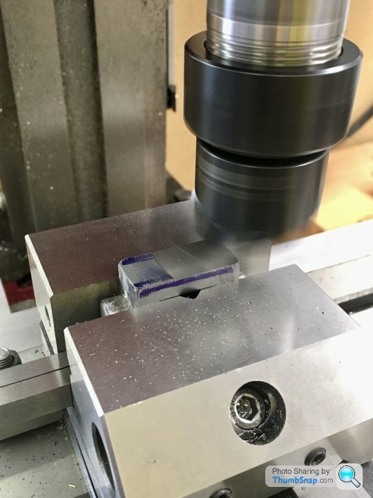
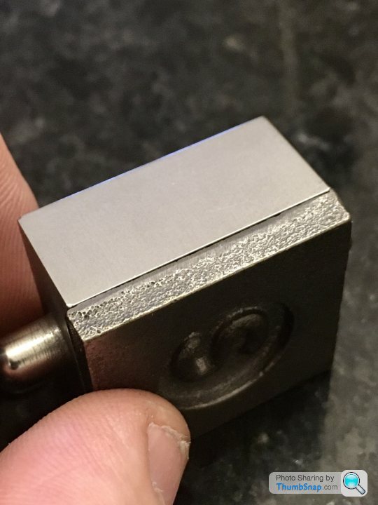
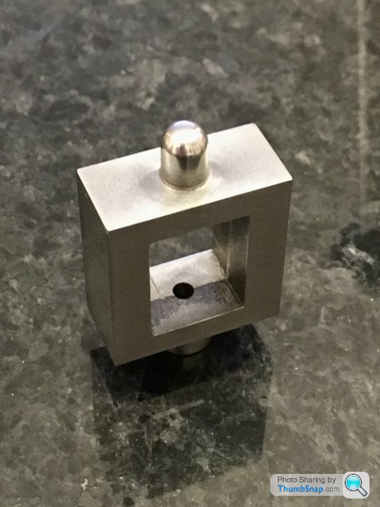
                            I tried the approach of cleaning up the outer surfaces, measuring, and re-cutting to size using the DROs, and with scribed lines as a sanity check:

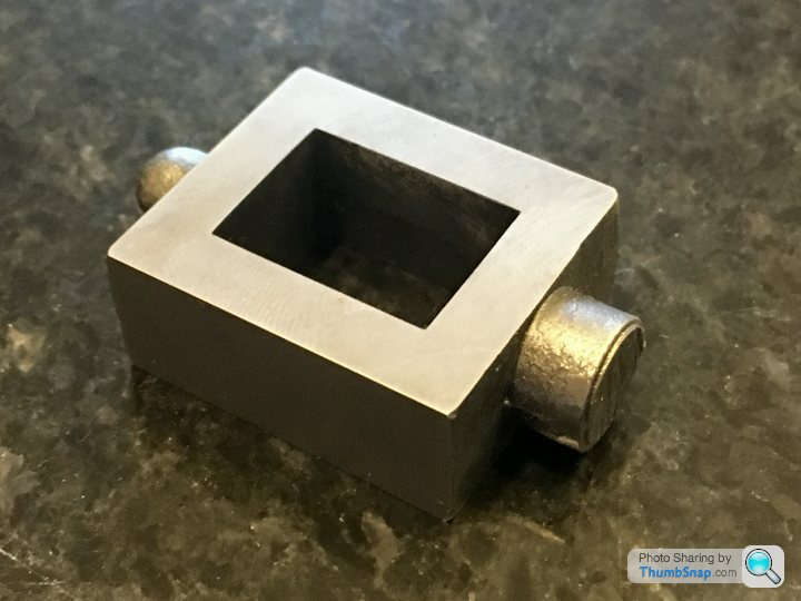
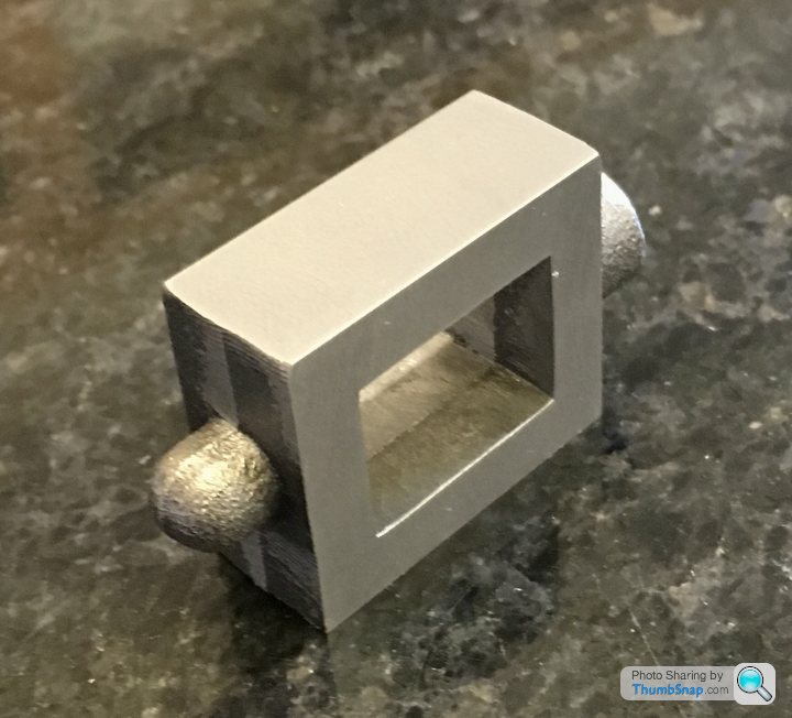
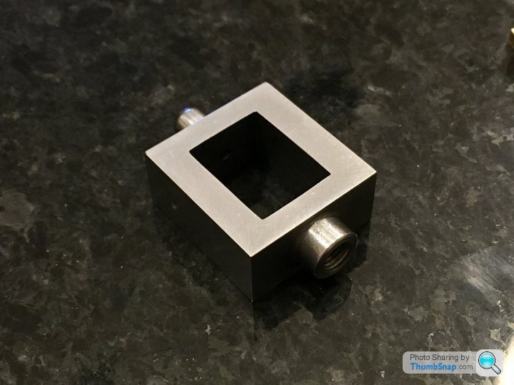
                            All faces were square and dimensions were spot-on to the limit of what I can measure, so that’s one method I can hopefully use from now on:

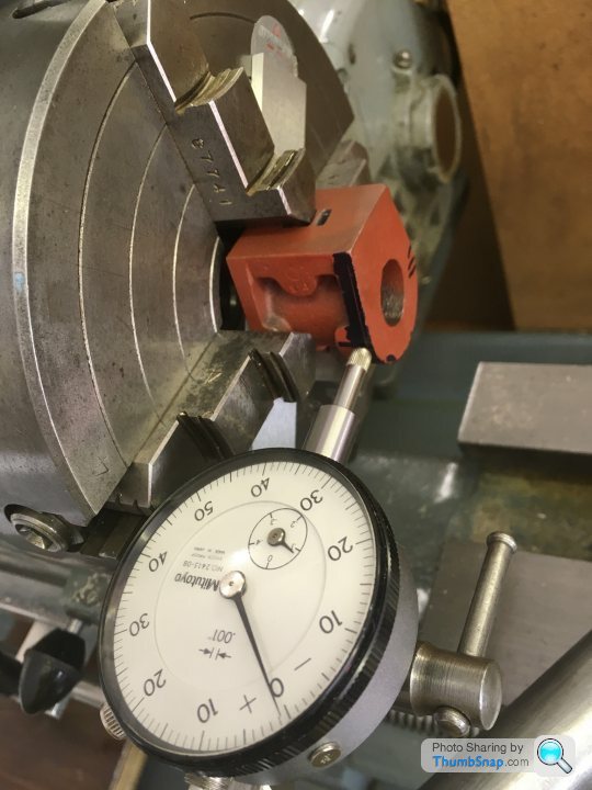
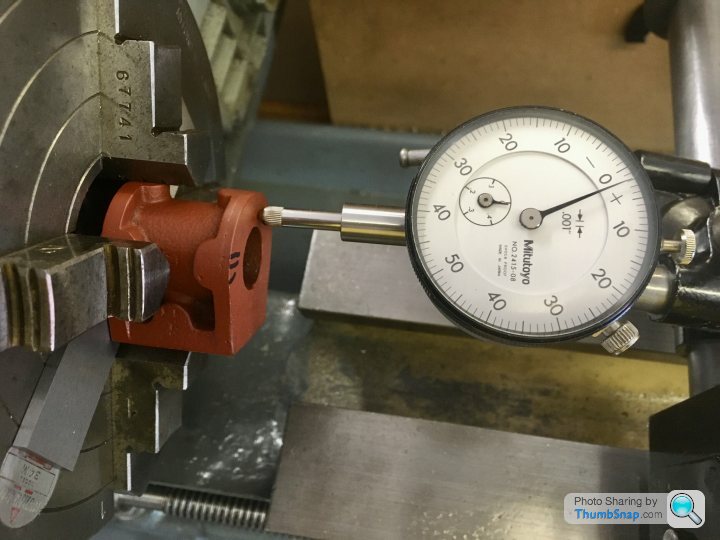
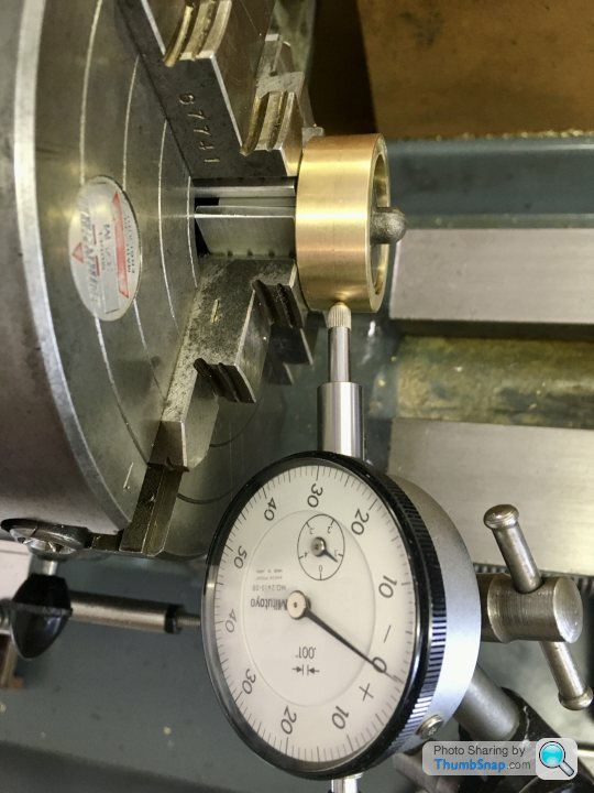
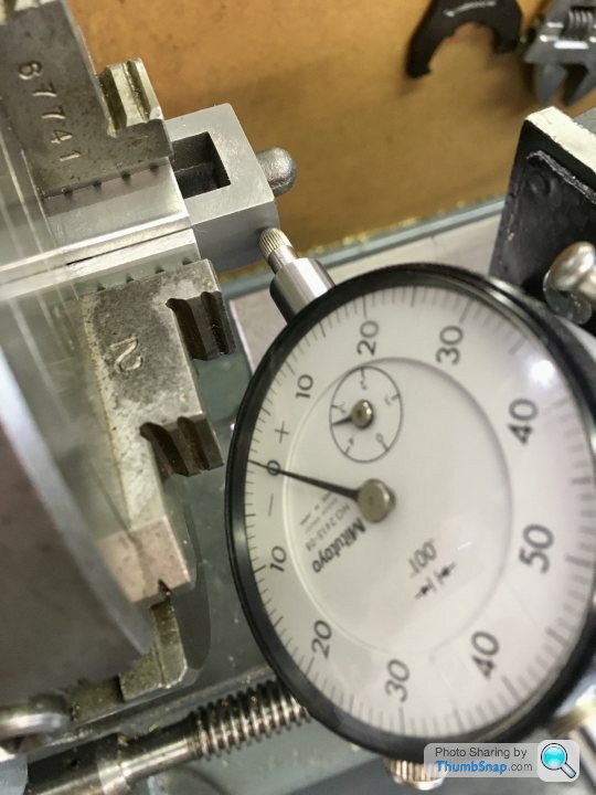
                            However, this still leaves the cast bosses to machine. After machining the sides, they may not now be in the exact centre of their respective faces (they appear to be less than 0.5mm out, but that's measuring to a cast surface, so may be more, may be less. I need to turn these in the 4 jaw chuck, but I couldn’t think how to centralise them accurately. I've seen a DTI used on each face in turn, and any difference in reading on oppsite sides corrected. This seems a bit dodgy, since it relies on getting the DTI pointer on precisely the same point, at the same angle on each opposing face. Any discrepancy in rotation angle will give a false reading. I suppose you are supposed to rock the chuck and take the minimum readings, but it seems a bit hit and miss. Anyway I’m going to try this centering ring I made from some scrap brass, and hopefully the result will be OK:

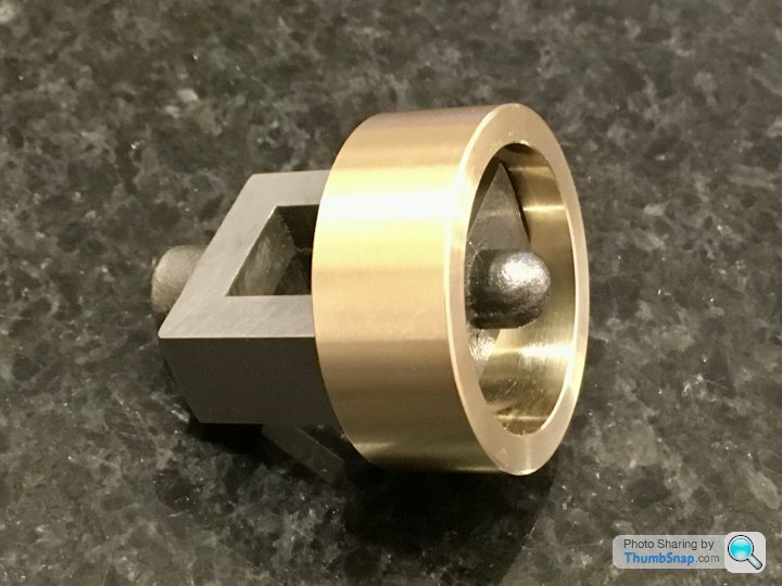
                            It’s a tight fit over the edges of the chest, and the idea is that I’ll fit it over the 10mm or so of the part protruding from the jaws. The back face of the ring will butt up to them. If I can center the part using a DTI on the ring, the excess material removed from the bosses should leave me with the finished drilled, tapped and reamed features bang in the middle, and the chuck jaws should ensure they are central within the box:

                            That’s the theory anyway. I might check using teh DTI on opposing face method, just to see what the numbers are.

                            Edited By Dr_GMJN on 15/06/2020 22:20:03

                            #480145
                            Dr_GMJN
                            Participant
                              @dr_gmjn

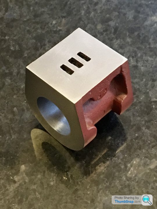
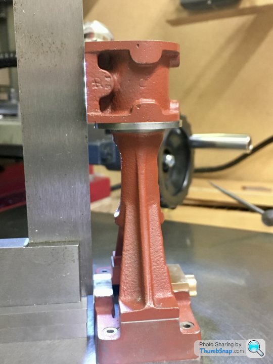
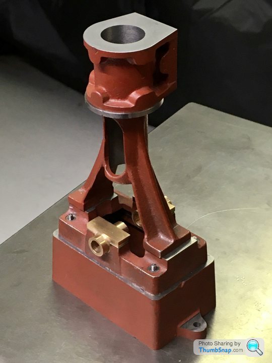
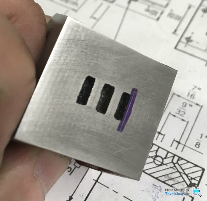
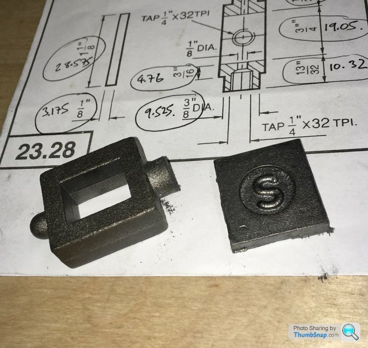
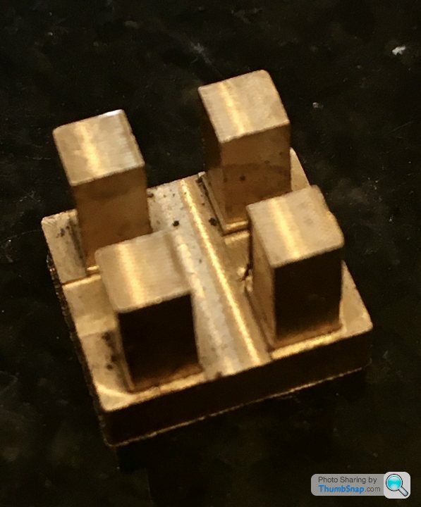
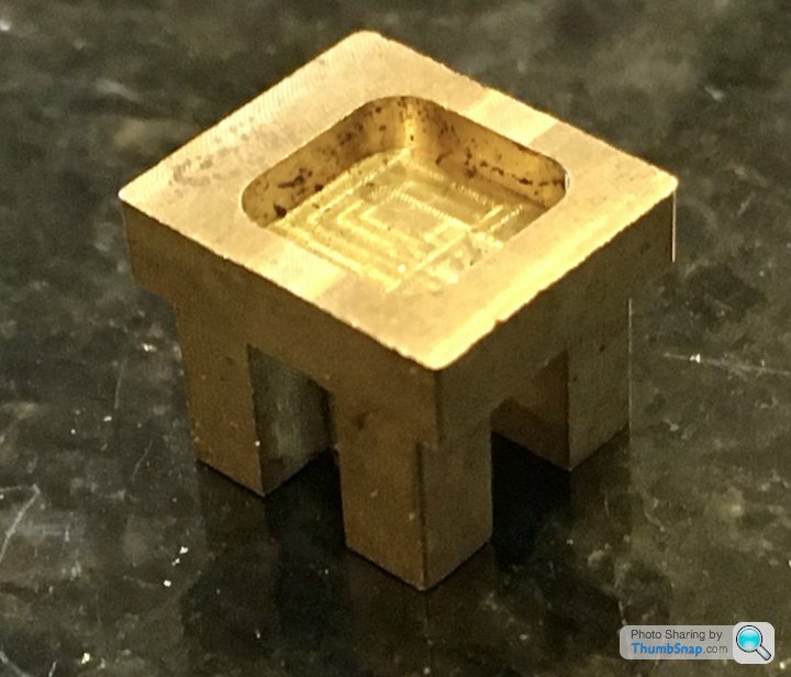
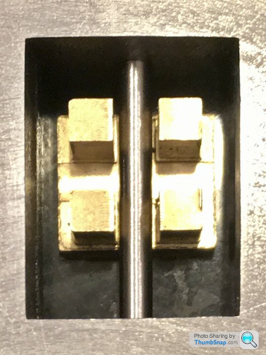
                              This is the valve slider as supplied in the kit:

                              Shame – in a strange way – because I was hoping to be able to say I’d machined everything myself when it’s finished, and it looks like a simple thing to make.

                              #480165
                              JasonB
                              Moderator
                                @jasonb

                                Looks like someone has machined it for you, you can see the marks

                                #480196
                                Anonymous

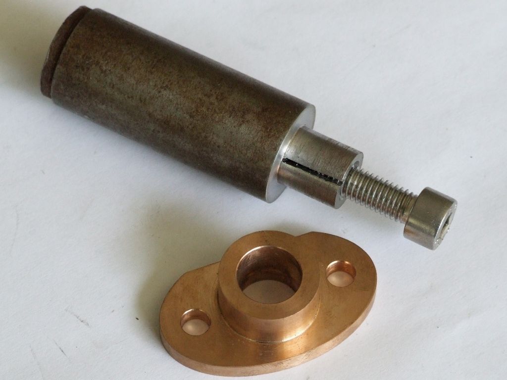
                                  A split bush is easier, and quicker, to make than a tapered arbor for holding work:

                                  split_bush.jpg

                                  The split bush shown was used to face the gland to length, turn the boss to diameter and face the back of the flange. Width of the flange and height of the boss are parallel to better than 0.02mm. A split boss can also provide a high clamping force. Here's one being used to cut a 6DP gear in EN24:

                                  6DP Pinion Gear

                                  Andrew

                                  #480203
                                  Dr_GMJN
                                  Participant
                                    @dr_gmjn

                                    Thanks Andrew, how do you make the bush?

                                    #480204
                                    Dr_GMJN
                                    Participant
                                      @dr_gmjn
                                      Posted by JasonB on 16/06/2020 10:04:42:

                                      Looks like someone has machined it for you, you can see the marks

                                      They do machined kits of course, so I suppose they might have run out of un-machined parts?

                                      #480205
                                      geoff walker 1
                                      Participant
                                        @geoffwalker1

                                        Hi Dr. G

                                        I recently bought a 10v slide valve from stuart, didn't ask for a machined one but that's what I got. Stuart may be now supplying them only fully machined.

                                        The one that I got had the cavity machined off centre so it was effectively useless. I rang stuart and they immediately sent me replacement which was machined perfect.

                                        Just looking at your photo the lands on either side of the cavity appear to be uneven which was the problem with mine. Could be just the photo deceiving me but it's worth checking.

                                        Geoff

                                        #480225
                                        Roderick Jenkins
                                        Participant
                                          @roderickjenkins93242

                                          If I remember correctly the slide valve used to be supplied as a hot pressed brass or bronze component that only needed to have the face flattened. I guess that the current ST owners try to replicate this with a lump of metal machined from bar stock.

                                          Stay well,

                                          Rod

                                          #480247
                                          Dr_GMJN
                                          Participant
                                            @dr_gmjn

                                            Rod, Geoff,

                                            It's strange they don't just provide a lump of brass to be machined.

                                            Any ideas why it was a pressing/forging in the first place?

                                            I just checked, and there is no drawing for this component.

                                            The land widths on mine are symmetrical side-side.

                                            #480250
                                            Anonymous
                                              Posted by Dr_GMJN on 16/06/2020 11:46:15:

                                              ….how do you make the bush?

                                              Simples!

                                              Turn the spigot to the wanted diameter and length. If I'm going to be facing I leave the spigot slightly short of the work. Drill and tap the hole. Ideally use a taper tap and only go in a few turns. You only need a couple of full threads and then the thread needs to taper off. So when the screw is inserted it binds and forces the spigot apart. Slit the spigot with a hacksaw. Clean up the saw lines with a needle file. Job done.

                                              Andrew

                                              #480252
                                              Dr_GMJN
                                              Participant
                                                @dr_gmjn
                                                Posted by Andrew Johnston on 16/06/2020 14:13:00:

                                                Posted by Dr_GMJN on 16/06/2020 11:46:15:

                                                ….how do you make the bush?

                                                Simples!

                                                Turn the spigot to the wanted diameter and length. If I'm going to be facing I leave the spigot slightly short of the work. Drill and tap the hole. Ideally use a taper tap and only go in a few turns. You only need a couple of full threads and then the thread needs to taper off. So when the screw is inserted it binds and forces the spigot apart. Slit the spigot with a hacksaw. Clean up the saw lines with a needle file. Job done.

                                                Andrew

                                                OK great, thanks. I'll try that on some of the other components. I still need to shorten the bearing bosses, so I'll need something like that to hold them.

                                                #480348
                                                Dr_GMJN
                                                Participant
                                                  @dr_gmjn

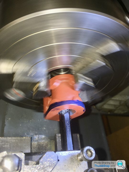
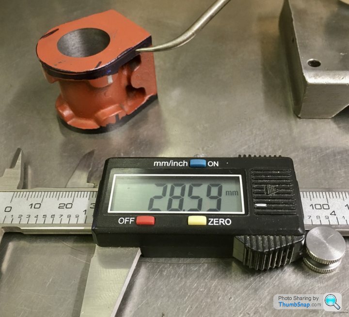
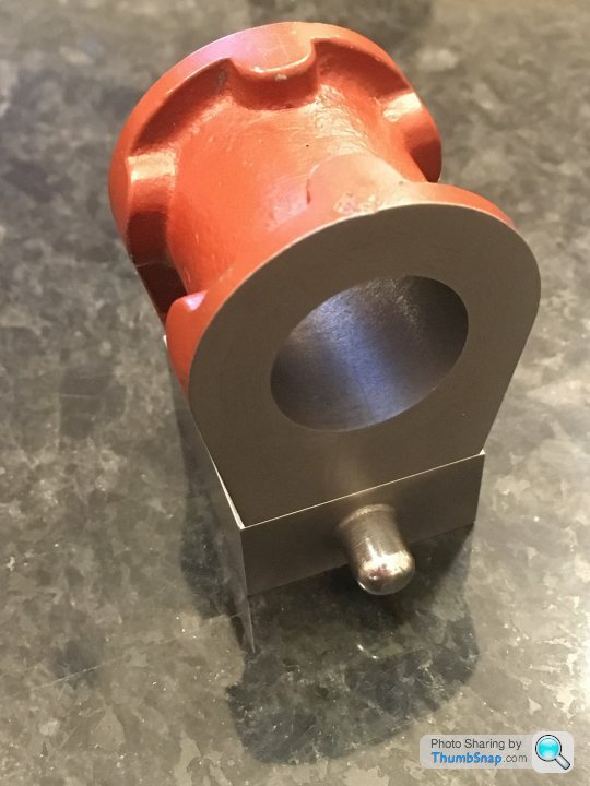
                                                  Made some more progress on the valve chest. I used the setting ring, and double checked using the depth to face method. All checked out to well within 0.001”

                                                  I set up for facing to a set depth using my end stop and a DTI on the saddle. Then forgot to tighten the tool holder, so it moved during the first cut. Ended up machining to a scribed line. Again.

                                                  Anyway, turned the part around and drilled, reamed and tapped the valve rod holes in one setup:

                                                  The holes seemed to be co-axial, and the 1/8” rod is a nice fit:

                                                  Slide valve seems to be central, so that’s OK:

                                                  It is a hair too long, purely due to the DTI/tool holder screw up, but it’s not noticeable, nor does it impact any other fit. I added 0.5mm excess to the sides to allow for the Aluminium lagging plate:

                                                  A side effect of this is that the cover plate will be fractionally too small once cleaned up:

                                                  So long as it’s equal all around I guess it’ll be ok. BTW the domed top boss was filed to shape while spinning in the chuck:

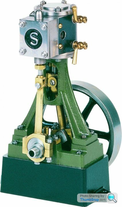
                                                  So now Im wondering about the best way to drill the mounting holes for the valve chest and cover. I don’t want to end up with it on the piss, like it is on the cover of my book. I’m thinking of clamping everything together, and drilling through as a stack.

                                                  Any advice on that? Thanks.

                                                  Edited By Dr_GMJN on 16/06/2020 21:51:10

                                                  #480362
                                                  geoff walker 1
                                                  Participant
                                                    @geoffwalker1

                                                    So now Im wondering about the best way to drill the mounting holes for the valve chest and cover. I don’t want to end up with it on the piss, like it is on the cover of my book. I’m thinking of clamping everything together, and drilling through as a stack.

                                                    I would drill the holes in the valve chest then clamp the chest to cylinder and spot drill through the holes on to the valve face.

                                                    Remove the chest and drill the holes tapping size inthe cylinder

                                                    Next clamp the chest to the cover and jig drill through

                                                    Should all line up perfect

                                                    Geoff

                                                    #480367
                                                    Dr_GMJN
                                                    Participant
                                                      @dr_gmjn

                                                      Thanks Geoff. I really want to ensure the studs/nuts are located perfectly on the cover plate; that’s why I thought clamping the whole lot together would be best. I would get the Centre point offsets directly from the cover edges. Assuming the cover-chest and chest-cylinder alignments are spot on (which I can easily see before going anywhere near them with a drill), the holes can’t look wrong. Of course, the drill could wander a bit, giving offset holes in the chest and cylinder, but they are invisible when complete.

                                                      If I drill the chest first, then fit the cover, The holes may not be central on the cover. If that makes sense?

                                                      One thing that would make me scrap a part (or parts), would be on the piss assembly in that area. Every time I look at the cover of my book it grates:


                                                      Edited By Dr_GMJN on 16/06/2020 22:48:55

                                                    Viewing 25 posts - 126 through 150 (of 385 total)
                                                    • Please log in to reply to this topic. Registering is free and easy using the links on the menu at the top of this page.

                                                    Advert

                                                    Latest Replies

                                                    Viewing 25 topics - 1 through 25 (of 25 total)
                                                    Viewing 25 topics - 1 through 25 (of 25 total)

                                                    View full reply list.

                                                    Advert

                                                    Newsletter Sign-up