Stuart 10V Build Log – Complete Beginner…

Advert

Stuart 10V Build Log – Complete Beginner…

Home Forums Work In Progress and completed items Stuart 10V Build Log – Complete Beginner…

Viewing 25 posts - 76 through 100 (of 385 total)
  • Author
    Posts
  • #475577
    Dr_GMJN
    Participant
      @dr_gmjn
      Posted by Martin Connelly on 28/05/2020 12:20:40:

      That is an aircraft with the old green and grey colour scheme. In 1981 29 squadron had about 15 aircraft but 228 OCU had more, I don't know their numbers. So the chances are it is not a 29 Squadron aircraft but if it is the chances are it is not one in the photos. That aircraft looks ready for the paint shop, I don't think any 29 Squadron aircraft would have been allowed to get that bad. Google Grimes cockpit utility light.

      Martin C

      I see. What's the significance of the light? I can see one behind the side screen.

      Advert
      #475580
      Martin Connelly
      Participant
        @martinconnelly55370

        Just identifying it for you.

        Martin C

        #475617
        Dr_GMJN
        Participant
          @dr_gmjn
          Posted by Martin Connelly on 28/05/2020 12:50:18:

          Just identifying it for you.

          Martin C

          Ah OK thanks.

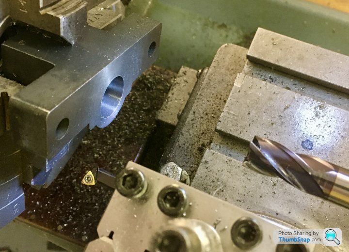
          Back to the basics – one thing I'm pretty sure isn't correct is the way I held the block in the chuck – if you look at the image below:

          Difficult to see, buy in that orientation, none of the flat faces are in contact with either the chuck face or the jaw ends. The square-ish extension at the rear was narrower than the central bore in the chuck. When machining the opposite face, the wide face was in direct contact with the chuck face, so no issue.

          I set it up by temporariy putting parallels between the 'wings' and the ends of the 2 opposed jaws. Once tapped back into contact, I removed the parallels and centered the piece with the centering rod. I then put the DTI on the face next to the existing bore to check it was normal to the rotation axis.

          So in other words, the part wasn't positively located along it's axis apart from friction with the jaws. If I put spacer pieces behind, they woul'd probably have flown out when spun. If I'd have put excess pressure on the tool, the part would probably have moved back, or at least out of true.

          Any advice? Thanks.

          #475632
          Martin Connelly
          Participant
            @martinconnelly55370

            What I can do with my lathe is put a collet in the spindle and put the chuck over it. The collet drawbar is hollow so I can put long bars in if required. I often do this with something like a 19mm/3/4" tube. Once the tube is gripped by the collet I skim the face to make sure it is running true then I can use it as a fixed backstop or as a flat face for setting parts to. If I had the need I would thread the end of a bar, make a bush to go on the thread and machine that flat in place to get a larger diameter than the collets hold or the chuck bore accepts.

            Martin C

            #475640
            Dr_GMJN
            Participant
              @dr_gmjn
              Posted by Martin Connelly on 28/05/2020 14:39:29:

              What I can do with my lathe is put a collet in the spindle and put the chuck over it. The collet drawbar is hollow so I can put long bars in if required. I often do this with something like a 19mm/3/4" tube. Once the tube is gripped by the collet I skim the face to make sure it is running true then I can use it as a fixed backstop or as a flat face for setting parts to. If I had the need I would thread the end of a bar, make a bush to go on the thread and machine that flat in place to get a larger diameter than the collets hold or the chuck bore accepts.

              Martin C

              Right, thanks.

              I don't have a collet like that – with a drawbar – for the lathe. I wonder if I could machine a disc to go in the centre register of the chuck though? The part would hold it in place axially, and the register would stop it falling out sideways. I'll have a look later.

              #475648
              Martin Connelly
              Participant
                @martinconnelly55370

                Have you seen this thread? I had to go back a few pages to find it.

                Chuck spacer tool

                Martin C

                #475651
                Dr_GMJN
                Participant
                  @dr_gmjn
                  Posted by Martin Connelly on 28/05/2020 15:25:44:

                  Have you seen this thread? I had to go back a few pages to find it.

                  Chuck spacer tool

                  Martin C

                  No – But I like it.

                  Cheers!

                  #475670
                  JasonB
                  Moderator
                    @jasonb

                    I usually do the same as you did and slip a couple of parallels between chuck face and back of work

                    #475673
                    Dr_GMJN
                    Participant
                      @dr_gmjn
                      Posted by JasonB on 28/05/2020 16:49:29:

                      I usually do the same as you did and slip a couple of parallels between chuck face and back of work

                      And remove them before machining, rather than securing them somehow?

                      Thanks.

                      #475687
                      JasonB
                      Moderator
                        @jasonb

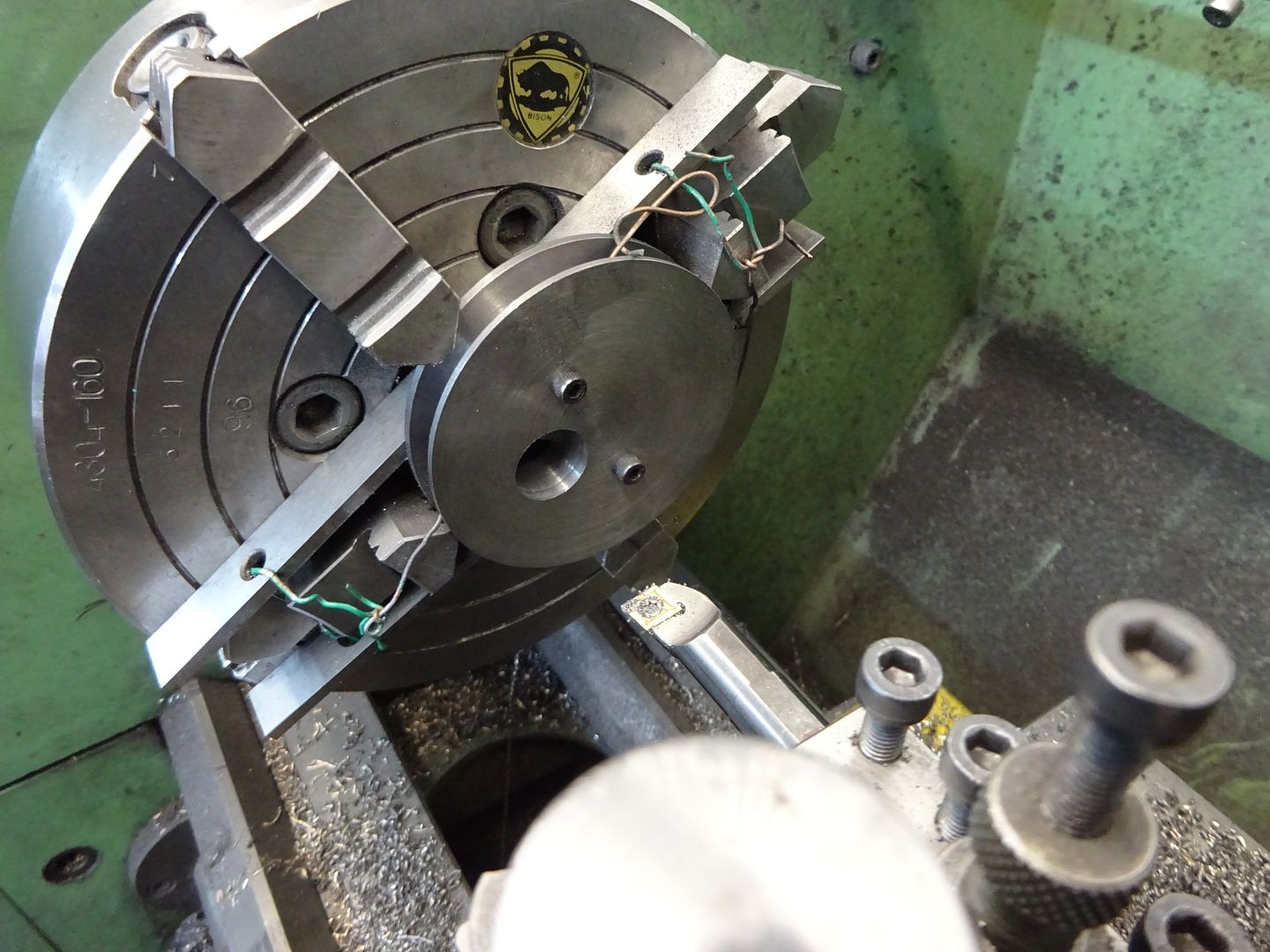
                        Yes, 99% of the time I would remove them, on the odd occasion where there may not be much metal to grip and therefore a risk of the cut pushing the work back I will either wire or zip tie them in place

                        Edited By JasonB on 28/05/2020 17:36:43

                        #475764
                        Dr_GMJN
                        Participant
                          @dr_gmjn
                          Posted by JasonB on 28/05/2020 17:33:47:

                          Yes, 99% of the time I would remove them, on the odd occasion where there may not be much metal to grip and therefore a risk of the cut pushing the work back I will either wire or zip tie them in place

                          Edited By JasonB on 28/05/2020 17:36:43

                          OK great, so I used the same method as that tonight for the other handwheel block.

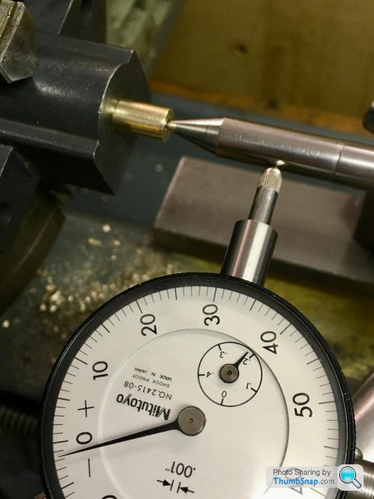
                          One change I made was to turn a brass spigot to knock into the existing bush in the block. The spigot had no measurable runout. I was able to easily center the block in the 4 jaw chuck using a DTI on the spigot so there was no measurable runout.

                          I'd centre drilled the spigot, so as an experiment, I used my centering rod again:

                          Again, just under 0.002" runout. No way I can get better than that. Even though I'm holding the rod to prevent it turning (if I let it turn it's worse – but no real surprise there), no matter what I do to the chuck, I always get that error; I got the same residual error when I put the point directly into the bush in the block yesterday. It can't be centering technique with the chuck, becasue I can easily zero it using a DTI on a known true cylinder.

                          Any thoughts on what I'm doing wrong here?

                          Anyhow, the block got machined – I calibrated the depth stop as suggested (but used calipers rather than slip gauges) – and the bearings were fitted. Both X & Y axes on the mill are now really smooth with minimal backlash.

                          Thanks!

                          #475778
                          Ron Laden
                          Participant
                            @ronladen17547

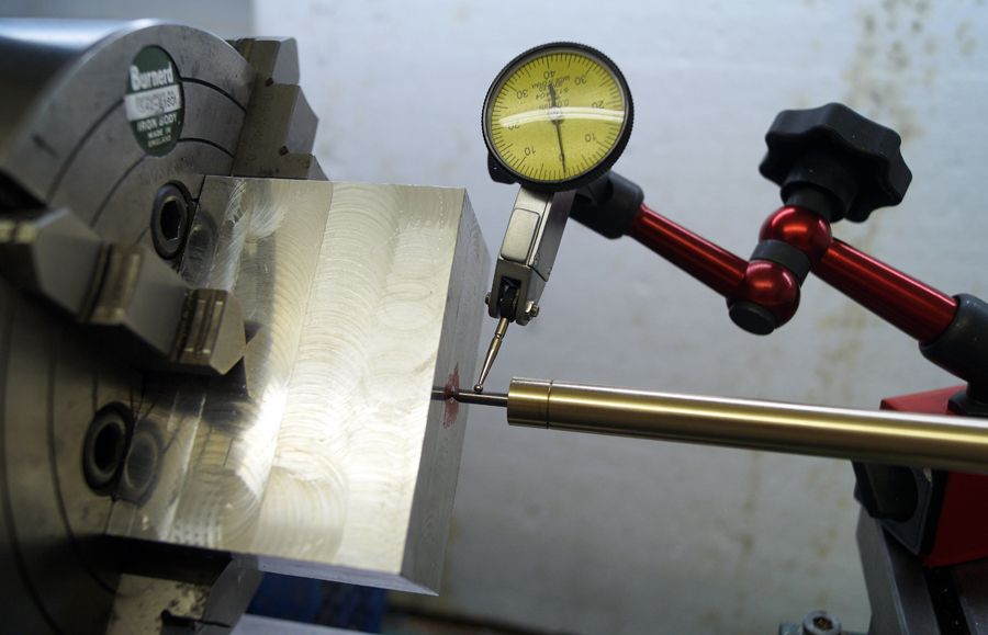
                            If the spigot has zero runout then I would suspect the centering bar and where you are measuring on the bar, have you tried measuring  close up against the spigot?

                            I measure close up against where the bar contacts the part. dsc07378.jpg


                            Edited By Ron Laden on 29/05/2020 04:43:18

                            #475782
                            Dr_GMJN
                            Participant
                              @dr_gmjn

                              Ron – I’m measuring about 1” back along the bar from the part. Since I’m measuring wobble rather that runout of the bar itself (assuming I stop it rotating) I don’t get why I can’t zero it – presumably in theory it doesn’t matter where along the bar I measure, but the biggest reading will be nearest the workpiece?

                              #475788
                              JasonB
                              Moderator
                                @jasonb

                                I think your angle on the end of the rod may be the problem. A ctr drilled and even a spot drilled hole will have a very slight flat on the bottom, your ctr punch mark from the other day will leave a wide 90deg cone and again may not have a perfectly flat bottom.

                                Now your very sharp pointed low angled indicator rod will touch the bottom of your mark not and not sit taper to taper.

                                So I would suggest you recut the end taper to 60deg inclusive angle, use a dot (prick) punch which are also ground to 60deg and if drilling to mark the position then use a small BS0 ctr drill and go in all the way with the pilot plus a small amount of the part that cuts the 60deg seat.

                                One other thing to bear in mind when making something like that plug, if your 3 jaw is a bit out it is unlikely the hole is concentric to the OD of the plug. For a job like this where there is an existing hole you would be better off just setting the lever of the dti to run against the inside of the hole, save the rod for when there is no suitable hole.

                                #475812
                                Dr_GMJN
                                Participant
                                  @dr_gmjn

                                  Thanks Jason, OK I'll re-cut the point again to 60 degrees inclusive. And I'll re-turn a portion of the adjacent shaft too.

                                  Is there a good way of re-profiling one of my centre punches to 60 degrees too?

                                  BTW the punch holes so far are only in the bras bearings – for the spigot yesterday I did centre drill it to make sure the point didn't bottom out. The spigot was turned in a collet, but of course if the center drill wandered it wouldn't be central.

                                  Also, I tried the bar in the existing through hole in the handwheel block, so it was in there to about half the taper depth (and obviously there was no bottom to it). Same story with runout.

                                  Anyway, I'll re-cut it and try again.

                                  #476413
                                  Dr_GMJN
                                  Participant
                                    @dr_gmjn

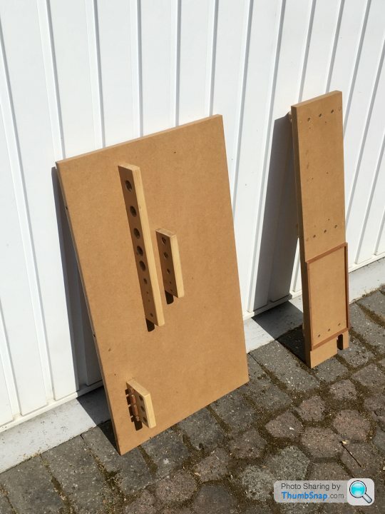
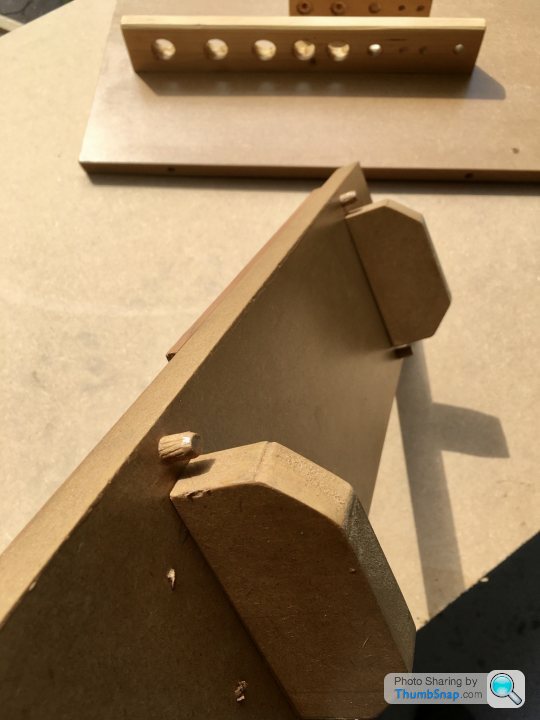
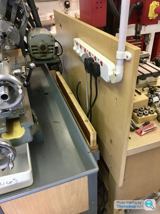
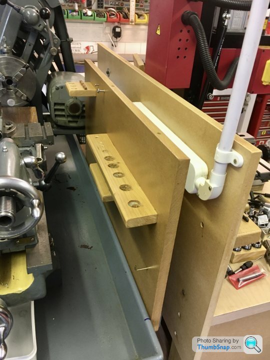
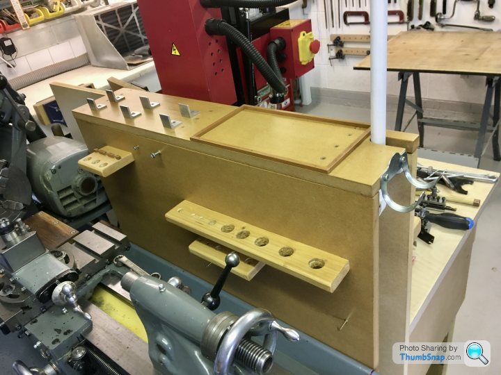
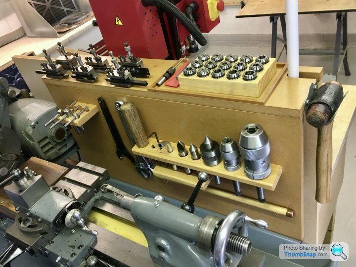
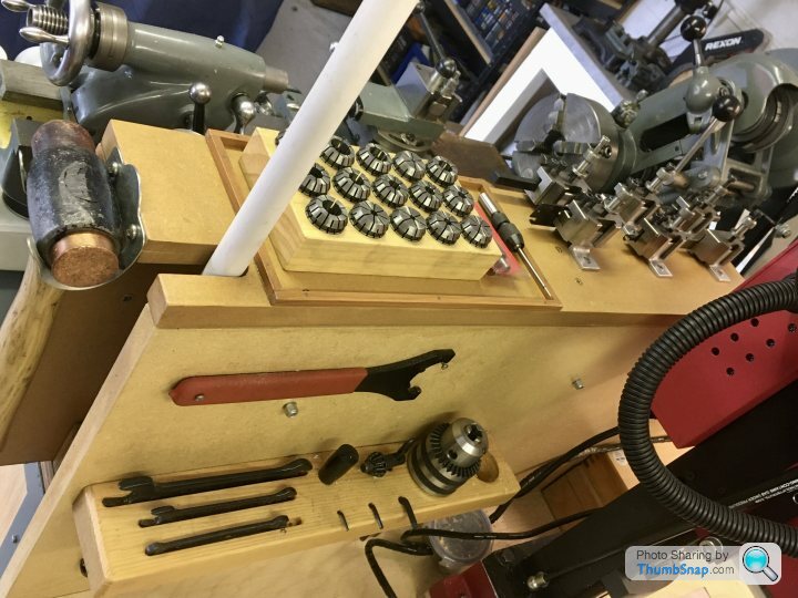
                                    I sacrificed a day on the 10V to make a tool board/shelf for the lathe and milling machines. I was wasting loads of time looking in my tool chest drawers for things. I’ve made it all slot together so I can quickly separate the two benches if I need to move them. Common tools like the collets and soft hammer are in the middle. I cut some aluminium angle up to put the lathe tool holders on.

                                    [url|https://thumbsnap.com/oNw6VGNc[/url]

                                    Quite pleased with that, especially since it was made out of scrap MDF so didn't cost anything.

                                    #476836
                                    Dr_GMJN
                                    Participant
                                      @dr_gmjn

                                      I've sidetracked this thread a bit, but now back to the 10V – the main bearings.

                                      I opted to go a bit off-piste, ignore the plan dimensions and mark the center of the cast semi-circle. My reasoning being that at the end of the day, if the turned bosses are not concentric with it, it’ll look wrong, and the specified dimensions are so close anyway, it won’t make any difference to the function of the engine.

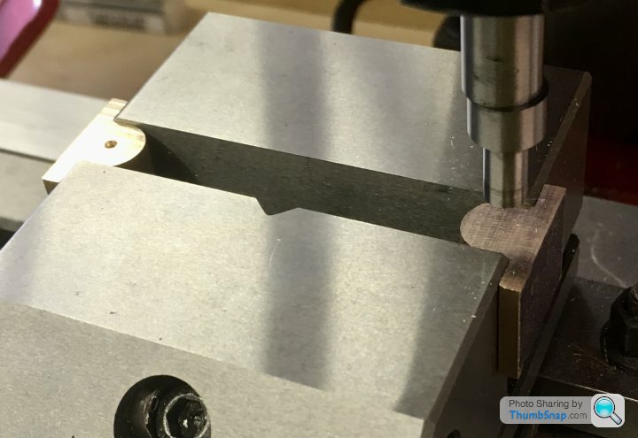
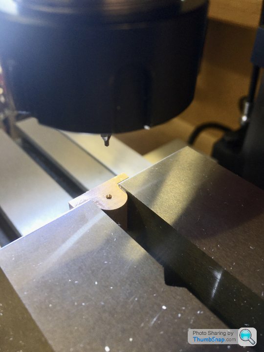
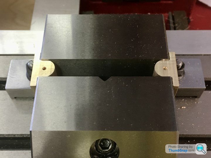
                                      My edge finder is 6mm diameter, so a fraction too large to take a direct measurement from the straight sides of the bosses. I decided to clamp both castings as shown, and calculate the centreline from the inside of the vice faces. Once locked in “y”, It was a simple task to offset from the exposed curved surfaces, and center drill them:

                                      No idea if that’s a good way of doing it, but it made sense to me and it seemed to work.

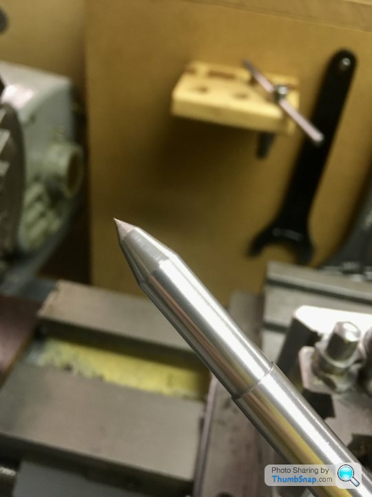
                                      Then onto the lathe to drill the crankshaft holes. I spent a good 45 minutes faffing about with shims in the 3 jaw chuck, and getting nowhere near true. In the end I cut some square spacers and used the 4 jaw chuck, and it was centred to less than 0.001” within a couple of minutes. I locally re-profiled my centering bar tip to 60 degrees included, and it seems OK now (thanks for the suggestion Jason!). Still needs holding to prevent rotation though:

                                      I drilled them progressively up to 6.8mm. My plan is to line drill both bearings in-situ to 6.9mm, then ream in the same setup.

                                      Wall thickness around the curved area is within about 0.004”. I doubt I could currently get any better, so that’s that.

                                      Next up: make a mandrel and cut the bosses on the lathe.

                                      #476878
                                      Dr_GMJN
                                      Participant
                                        @dr_gmjn

                                        #476884
                                        Martin Connelly
                                        Participant
                                          @martinconnelly55370

                                          I would not get in the habit of holding two parts at once in the vice like that. There is always the chance that one is not held as tightly as you think and will come loose when it is being machined. It is relying on the two parts being nearly/exactly the same width where they are gripped and the vice being sloppy enough to twist the moving jaw to even out the grip on the two parts. Copper and its alloys are grabby, the bearings could easily have been twisted out of the ends of the vice if a drill had been grabbed by the alloy. One at a time in the centre of the vice may seem a bit slower but it is going to give a better grip and twisting of the workpiece would be next to impossible. I would suggest a vice stop and parallels would help when you have more than one item to machine the same way. Parallels support the part solidly. Your method of holding them could cause them to be pushed downwards. If you had asked if it was a good setup to drill them I would have emphatically said no. Just for marking out is not a problem but it is something to think about for the future.

                                          Martin C

                                          Edited By Martin Connelly on 02/06/2020 09:30:10

                                          #476926
                                          Dr_GMJN
                                          Participant
                                            @dr_gmjn
                                            Posted by Martin Connelly on 02/06/2020 09:27:19:

                                            I would not get in the habit of holding two parts at once in the vice like that. There is always the chance that one is not held as tightly as you think and will come loose when it is being machined. It is relying on the two parts being nearly/exactly the same width where they are gripped and the vice being sloppy enough to twist the moving jaw to even out the grip on the two parts. Copper and its alloys are grabby, the bearings could easily have been twisted out of the ends of the vice if a drill had been grabbed by the alloy. One at a time in the centre of the vice may seem a bit slower but it is going to give a better grip and twisting of the workpiece would be next to impossible. I would suggest a vice stop and parallels would help when you have more than one item to machine the same way. Parallels support the part solidly. Your method of holding them could cause them to be pushed downwards. If you had asked if it was a good setup to drill them I would have emphatically said no. Just for marking out is not a problem but it is something to think about for the future.

                                            Martin C

                                            Edited By Martin Connelly on 02/06/2020 09:30:10

                                            Thanks Martin – understood; I wouldn't consider any significant machining operation while holding parts like that. My thoughts were:

                                            1) The casting has been cut in half, and so the width is essentially the same for both parts – they measured exactly the same with my calipers. If they'd have measured differently I wouldn't have tried it, not least becasue as you say the jaws wouldn't have been parallel, which would have affected the reading, and not done the vice any good.

                                            2) I was only centre drilling to a couple of mm, so very low forces involved.

                                            On the face of it, it seemed like a good way of getting around the issue of not having enough room to find an edge.

                                            #477113
                                            Dr_GMJN
                                            Participant
                                              @dr_gmjn

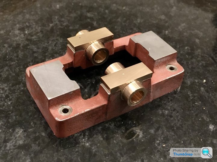
                                              Turned a bearing mandrel from some scrap brass rod, and threaded the end M5:

                                              I made a spacer for the end, to the correct boss diameter, so I could easily see when I was nearly at the right size:

                                              Marked up and cut:

                                              I’ve never tried intermittent cuts on the lathe before, but it was fine.

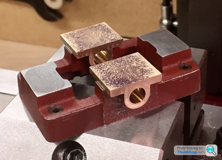
                                              I’ve polished to top surfaces with wet and dry on the surface plate, ready for drilling. Shame there are some surface flaws I can’t get rid of.

                                              I left all the bosses long, so I could size them precisely to the crank webs and eccentric. Not sure how I’ll hold them for that – perhaps in the collet chuck, or modify my mandrel somehow.

                                              #477136
                                              Dr_GMJN
                                              Participant
                                                @dr_gmjn

                                                All,

                                                I'd like to put a very small chamfer around the top edge of the rectangular bearing plates. It looks like I've got about 1mm clearance between the top of the boss and the top surface, so a 0.5mm x 45 degree chamfer all around should be OK. I have a 45 degree chamfering tool.

                                                I tried chamfering around my travel stop and it worked OK for what it was, but for this, I need to be very precise.

                                                What I found with aluminium was it was difficult to determine when the tool had touched the edge of the work, becasue it was soft. I think it'll be similar with brass. If the chamfer is only 0.5mm, then any excess cut depth would give an inconsistent chamfer width.

                                                Any tips for setting up this job for chamfering? I suppose everything has to be absolutely square and level before cutting, but these parts are quite small.

                                                Thanks!

                                                #477148
                                                JasonB
                                                Moderator
                                                  @jasonb

                                                  Probably quicker to file than set up and mill.

                                                  If you really want to machine it then a but of simple maths once you have located the edge, and end of tool should get a consistent result

                                                  #477153
                                                  Dr_GMJN
                                                  Participant
                                                    @dr_gmjn
                                                    Posted by JasonB on 03/06/2020 10:04:15:

                                                    Probably quicker to file than set up and mill.

                                                    If you really want to machine it then a but of simple maths once you have located the edge, and end of tool should get a consistent result

                                                    Thanks Jason, so if machining, you'd calculate the offset to put into the machine, or would you mark out and cut up to the line? I was thinking that cutting to a line once the tool depth is set to give a small excess, it would eliminate any errors in initial setting when using the DROs.

                                                    I was going to mark out and file (might still do that), but the area around the top of the boss is difficult to access.

                                                    #477155
                                                    JasonB
                                                    Moderator
                                                      @jasonb

                                                      I would not mark it out. Though you could blue the whole thing to make it easier to see what you have cut as a double check.

                                                    Viewing 25 posts - 76 through 100 (of 385 total)
                                                    • Please log in to reply to this topic. Registering is free and easy using the links on the menu at the top of this page.

                                                    Advert

                                                    Latest Replies

                                                    Viewing 25 topics - 1 through 25 (of 25 total)
                                                    Viewing 25 topics - 1 through 25 (of 25 total)

                                                    View full reply list.

                                                    Advert

                                                    Newsletter Sign-up