Stuart 10V Build Log – Complete Beginner…

Advert

Stuart 10V Build Log – Complete Beginner…

Home Forums Work In Progress and completed items Stuart 10V Build Log – Complete Beginner…

Viewing 25 posts - 51 through 75 (of 385 total)
  • Author
    Posts
  • #475241
    JasonB
    Moderator
      @jasonb

      The drawing has been that way for years, new castings may be a little smaller. It's not a critical dimension so could be altered. Something like 0.2mm deep cut or to round things up nicely 10.50mm dia

      This is where experience over time comes in to know when you need to hit a size dead on, where it can have a bit of tolerence and where it is not critical. The easy availablity of measuring equipment these days does seem to have people looking for sizes to several decimal places where as in the past all the builder would have had was a steel rule and made just as good an engine.

      Advert
      #475248
      Dr_GMJN
      Participant
        @dr_gmjn
        Posted by JasonB on 27/05/2020 07:06:51:

        The drawing has been that way for years, new castings may be a little smaller. It's not a critical dimension so could be altered. Something like 0.2mm deep cut or to round things up nicely 10.50mm dia

        This is where experience over time comes in to know when you need to hit a size dead on, where it can have a bit of tolerence and where it is not critical. The easy availablity of measuring equipment these days does seem to have people looking for sizes to several decimal places where as in the past all the builder would have had was a steel rule and made just as good an engine.

        Thanks Jason – understood about the drawings – they are obviously un-toleranced, so some intuition is needed. It was just that the inner faces of the bosses form the crankshaft thrust bearings, and the brass as supplied gives you half the bearing width; 0.2mm is the drawing face width, but that leaves you with virtually no land around the boss.

        I might turn a spacer to clamp the boss to the mandrel, making it just small enough to get a defined land around the it, and use that as a guide for cutting.

        #475252
        paul rushmer
        Participant
          @paulrushmer83015

          If my memory serves me correctly (its a long time ago I built mine 40 years) I used a 11mm ballnose cutter and the bearings were a brass extrusion. Andrew Smith in his book suggested using a piece of 16 SWG? sheet wrapped round the curved area and the three jaw chuck. Hope this helps.

          Paul

          #475289
          paul rushmer
          Participant
            @paulrushmer83015

            My memory is not what it was, the packing used should be 0.7mm or 1/32. Hope fully I have attached the revalent page from the book.

            Paul002.jpg

            #475294
            JasonB
            Moderator
              @jasonb

              Also interesting that the metric drawing gives the diameter either side as 10mm which would be more than enough to compensate for any differences in the now cast part.

              #475439
              Dr_GMJN
              Participant
                @dr_gmjn

                Thanks Paul and Jason,

                I have that book – I wonder why it's missing the 11mm dimension for the 7/16" block width?

                I've seen a couple of online builds where they've assumed the 1/4" dimension is the depth of the bearing axis below the upper surface of the block, and marked it out as such, ie with the as-cast upper surface as a datum. I don't think this is right: If the bosses are to be concentric with the semi-circular lower block, then that 1/4" below the surface will be slightly wrong. I assume it's actually the flat top face of the bearing that should be struck 1/4" up from the axis of the hole (or the lower O/D of the block).

                All pretty irrelevant in practical terms, but it's interesting how people interpret the drawings w.r.t. the parts they're supplied.

                #475440
                Dr_GMJN
                Participant
                  @dr_gmjn

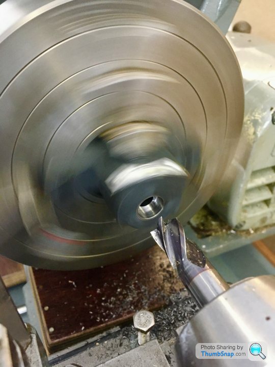
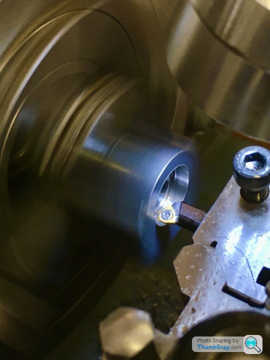
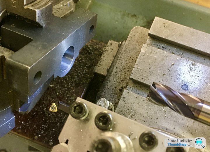
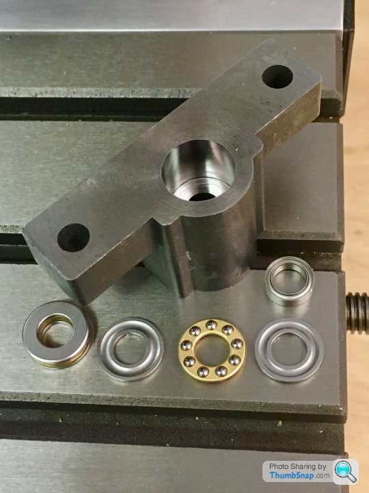
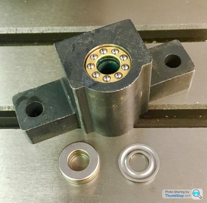
                  Got distracted with some modifications to the mill – I got some thrust bearings and ball races for the x & y hand wheels. As standard they have plain bushes, and metal to metal face contact on the leadscrew ends. The stiction and feel isn’t nice.

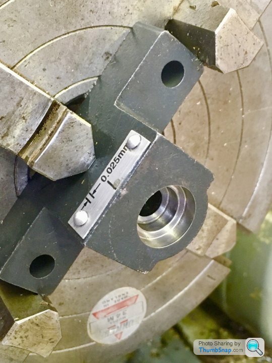
                  So I removed the hand wheel blocks, mounted them in a 4 jaw chuck and milled/bored the bearing pockets. I used my home made centering bar to align the block – I could get it to about 0.00075” but no better for some reason.

                  Once re-assembled backlash was reduced by about 30%, just by being able to fully tighten the hand wheel nut. The biggest difference is in feel – night and day improvement with no noticeable stiction.

                  Very happy with that little exercise, especially as it’s the first time I’ve used a 4 jaw chuck. Next the y-axis, then back to motorise the x-axis so I can get more consistent surface finishes.

                  ETA: It took a lot of trial and error to get to my calculated bearing step depths, cutting a bit, then using the depth gauge on my digital calipers. Even then they were a bit out. I did use my new depth stop, and the fine adjustment screw on the end. I suppose I could calibrate that if I knew the screw pitch, but it's not a great way of doing it. What's the best way of ascertaining depth when blind drilling with the tailstock feed? Mine's got a very rough scale etched onto the tailstock shaft, no good for mm work.

                  Thanks!

                  Edited By Dr_GMJN on 27/05/2020 21:20:28

                  #475442
                  Dr_GMJN
                  Participant
                    @dr_gmjn

                    BTW can anyone recommend a decent DCMT straight tool holder?

                    #475470
                    Martin Connelly
                    Participant
                      @martinconnelly55370

                      With a hard stop use your compound slide to set depth. With the compound in line with the ways wind it to the right. Set the stop so that the tool is close to the workpiece face when the carriage is on the stop. Wind the compound until the tool touches the workpiece and set the compound dial to zero. Move the carriage away from the stop and advance the compound by the required depth. All set to cut to the correct depth.

                      Martin C

                      #475486
                      JasonB
                      Moderator
                        @jasonb

                        The ideal dimension would be from the underside of the two mounting lugs to the ctr of the hole as that is what ultimately sets the height relative to the A frame standard, cylinder etc.

                        When you say straight do you mean a holder that presents the tool straight on so the insert can be used for Whit threading?

                        Some people mount a cheap micrometer body to their depth stop or you can put a known size packer or even gauge block between stop and carriage then touch the tool to the work and when the packer is removed the tool will move in by that amount.

                        #475489
                        Ron Laden
                        Participant
                          @ronladen17547

                          Just curious but how did you manage to use your centering bar to centre for a hole when the hole already exists, did you fit a plug or something into the hole..?

                          #475496
                          Dr_GMJN
                          Participant
                            @dr_gmjn
                            Posted by Martin Connelly on 27/05/2020 23:29:00:

                            With a hard stop use your compound slide to set depth. With the compound in line with the ways wind it to the right. Set the stop so that the tool is close to the workpiece face when the carriage is on the stop. Wind the compound until the tool touches the workpiece and set the compound dial to zero. Move the carriage away from the stop and advance the compound by the required depth. All set to cut to the correct depth.

                            Martin C

                            Thanks Martin. I should have thought of that. A couple of points:

                            1) none of my dials can be zeroed. I know it’s just simple maths, but it’s a pain to constantly be working to random figures – especially when the dials aren’t very clear at the best of times.

                            2) with the compound slide, I set it using the angle scale on the mount. Because I’m doing it manually I always wonder if I’m cutting (or moving in) a slight taper. Is there a quick way of setting it perfectly true?

                            Cheers.

                            #475498
                            Dr_GMJN
                            Participant
                              @dr_gmjn
                              Posted by JasonB on 28/05/2020 07:12:25:

                              The ideal dimension would be from the underside of the two mounting lugs to the ctr of the hole as that is what ultimately sets the height relative to the A frame standard, cylinder etc.

                              When you say straight do you mean a holder that presents the tool straight on so the insert can be used for Whit threading?

                              Some people mount a cheap micrometer body to their depth stop or you can put a known size packer or even gauge block between stop and carriage then touch the tool to the work and when the packer is removed the tool will move in by that amount.

                              Thanks Jason.

                              I have Right and left hand DCMT tools, but I’m always fiddling with the tool holder angle. If I’m turning a bar and want a small chamfer of the end for example. I thought with a straight holder I could turn to size and chamfer without messing about. Then again if I wanted to face something I’d have to change the angle anyway. Maybe my technique is wrong I don’t know.

                              The gauge block idea sounds good. I got an old set off ebay, and only use them as weights for holding down flat parts when I’m building paper model ships…

                              cheers.

                              #475500
                              Dr_GMJN
                              Participant
                                @dr_gmjn
                                Posted by Ron Laden on 28/05/2020 07:32:56:

                                Just curious but how did you manage to use your centering bar to centre for a hole when the hole already exists, did you fit a plug or something into the hole..?

                                Ron, no I just shoved the point into the existing hole. It went about half way in.

                                The issue I’ve got with the centering bar is that it naturally wants to turn with the work, so if I forget to hold the tail stock end I get a false reading because I’m measuring the runout error of the bar itself as well as wobble. I tried modding it by re-turning the point, and turning about 1” of the adjacent bar in the same setup, but I still somehow get a few thou runout error.

                                Like I say, I don’t really know what Im doing yet, but in this case the Bearing pockets somehow worked out great.

                                For the y-axis I might turn a short spigot and push it into the existing hole and use that to center it rather than the bar. I did try to find a twist drill, but none were a tight fit.

                                cheers.

                                #475521
                                Martin Connelly
                                Participant
                                  @martinconnelly55370

                                  The compound only needs to be close to the correct position for this to work since the cosine of a small angle is close to 1.

                                  If you want to set the compound slide to align it to the ways then mount a dti on the compound slide and a stiff parallel bar in the chuck. Moving the dti along the bar with the compound should give similar results to moving the dti along the bar with carriage movement.

                                  To set the dials up to read zero using the earlier procedure loosen the tool in the holder. With the carriage against the stop move the compound so that the dial reads zero. Reposition the tool in tbe holder so that it is touching the workpiece face. Back off the carriage and advance the compound the desired depth.

                                  Martin C

                                  #475524
                                  Dr_GMJN
                                  Participant
                                    @dr_gmjn
                                    Posted by Martin Connelly on 28/05/2020 09:45:11:

                                    The compound only needs to be close to the correct position for this to work since the cosine of a small angle is close to 1.

                                    If you want to set the compound slide to align it to the ways then mount a dti on the compound slide and a stiff parallel bar in the chuck. Moving the dti along the bar with the compound should give similar results to moving the dti along the bar with carriage movement.

                                    To set the dials up to read zero using the earlier procedure loosen the tool in the holder. With the carriage against the stop move the compound so that the dial reads zero. Reposition the tool in tbe holder so that it is touching the workpiece face. Back off the carriage and advance the compound the desired depth.

                                    Martin C

                                    Thanks Martin. If I make a DTI holder, are there any particular design features that are useful? I've got both a finger type and a plunger type. Using a magnetic base is a bit cumbersome, so a holder would be good.

                                    I suppose having gone to the trouble of making an adjustable stop, I should have though more about the obvious way to actually use it – touching the drill edge then spacing back from the stop…Ah well it's all good stuff to learn!

                                    #475526
                                    Martin Connelly
                                    Participant
                                      @martinconnelly55370

                                      If you have a dti with dovetails and a dovetail mount like a short rod then the simplest holder is a bit of bar with a hole for the dovetail mount and a clamp screw. Just needs a bit of thought to get the lever on the centre line with the face in a readable position.

                                      Martin C

                                      #475527
                                      Dr_GMJN
                                      Participant
                                        @dr_gmjn
                                        Posted by Martin Connelly on 28/05/2020 09:45:11:

                                        BTW is that a 29 Squadron Phantom in your picture? I built an Airfix 1:72 Bristol Bulldog (with a lot of mods) from 29 squadron recently – I thought I recognised that diamond pattern:

                                        #475530
                                        JasonB
                                        Moderator
                                          @jasonb

                                          Very Nice

                                          You want a neutral tool holder so something like this should do, I have a couple of their other holders thatseem to work fine.

                                          However you will still need to swing the toolpost round if you want to do a 45deg chamfer, it may be better to get a neutral holder to take square inserts then you just leave the toolpost so the tool is square on to the lathes axis, your RH & RH tools should also work in this position so no need to play about with angles

                                          #475532
                                          Dr_GMJN
                                          Participant
                                            @dr_gmjn
                                            Posted by JasonB on 28/05/2020 10:14:26:

                                            Very Nice

                                            You want a neutral tool holder so something like this should do, I have a couple of their other holders thatseem to work fine.

                                            However you will still need to swing the toolpost round if you want to do a 45deg chamfer, it may be better to get a neutral holder to take square inserts then you just leave the toolpost so the tool is square on to the lathes axis, your RH & RH tools should also work in this position so no need to play about with angles

                                            Thanks Jason – yes, the square tool holder would be good, but I guess it means getting new sets of inserts for different materials. Not the end of the world. BTW the Sandvik DCMT holders (And boring bars and parting tool) were given to me, so they don't owe me anything. They are very good TBH.

                                            #475534
                                            Dr_GMJN
                                            Participant
                                              @dr_gmjn
                                              Posted by Martin Connelly on 28/05/2020 10:03:26:

                                              If you have a dti with dovetails and a dovetail mount like a short rod then the simplest holder is a bit of bar with a hole for the dovetail mount and a clamp screw. Just needs a bit of thought to get the lever on the centre line with the face in a readable position.

                                              Martin C

                                              Martin, the finger DTI has dovetails and a spigot, so that's easy. The plunger type is much bigger, and only has a mounting lug with a hole in it on the back. I suppose a square bar with a tapped hole in the end would be OK for that?

                                              Is normal practice to mount them with the plunger or finger on the side of the work facing you? I'm using this method, then adjusting the 4-jaw chuck by moving the screws to the plunger position and correcting back to the mid point of deflection….or trying to!

                                              #475553
                                              Martin Connelly
                                              Participant
                                                @martinconnelly55370

                                                Yes, finger on the side but it can be front or back of the bar, probably easier at the front for the compound position check.

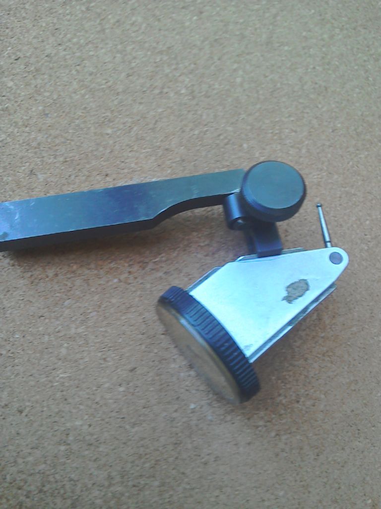
                                                My setup would be this because that's what I have to hold the dti.

                                                img_20200528_105558.jpg

                                                Martin C

                                                #475556
                                                Martin Connelly
                                                Participant
                                                  @martinconnelly55370

                                                  Nice job on the model. This is the full photo the avatar picture is from. I am in the photo but am not the person in front of the badge I think it is 1981. The second photo is one I took inside the hangar. We were in the process of changing paint schemes.

                                                  sqn_photo_81.jpg

                                                  hangar 3.jpg

                                                  Martin C

                                                  Edited By Martin Connelly on 28/05/2020 11:34:54

                                                  #475565
                                                  Dr_GMJN
                                                  Participant
                                                    @dr_gmjn
                                                    Posted by Martin Connelly on 28/05/2020 11:31:43:

                                                    Nice job on the model. This is the full photo the avatar picture is from. I am in the photo but am not the person in front of the badge I think it is 1981. The second photo is one I took inside the hangar. We were in the process of changing paint schemes.

                                                    sqn_photo_81.jpg

                                                    hangar 3.jpg

                                                    Martin C

                                                    Edited By Martin Connelly on 28/05/2020 11:34:54

                                                    Nice.

                                                    This is me – Coningsby Airshow, 1981. I remember the pilot saying "whatever you do, don't touch anything that's yellow and black". I wonder if it's the same aircraft…

                                                    #475573
                                                    Martin Connelly
                                                    Participant
                                                      @martinconnelly55370

                                                      That is an aircraft with the old green and grey colour scheme. In 1981 29 squadron had about 15 aircraft but 228 OCU had more, I don't know their numbers. So the chances are it is not a 29 Squadron aircraft but if it is the chances are it is not one in the photos. That aircraft looks ready for the paint shop, I don't think any 29 Squadron aircraft would have been allowed to get that bad. Google Grimes cockpit utility light.

                                                      Martin C

                                                    Viewing 25 posts - 51 through 75 (of 385 total)
                                                    • Please log in to reply to this topic. Registering is free and easy using the links on the menu at the top of this page.

                                                    Advert

                                                    Latest Replies

                                                    Viewing 25 topics - 1 through 25 (of 25 total)
                                                    Viewing 25 topics - 1 through 25 (of 25 total)

                                                    View full reply list.

                                                    Advert

                                                    Newsletter Sign-up