Stuart 10V Build Log – Complete Beginner…

Advert

Stuart 10V Build Log – Complete Beginner…

Home Forums Work In Progress and completed items Stuart 10V Build Log – Complete Beginner…

Viewing 25 posts - 276 through 300 (of 385 total)
  • Author
    Posts
  • #496999
    SillyOldDuffer
    Moderator
      @sillyoldduffer
      Posted by Dr_GMJN on 21/09/2020 07:51:48:

      I heard wood dust doesn’t do machine tools any good – something to do with silica or something in the wood. Anyway it won't be a regular thing, so I guess it's OK.

      It's true some woods are abrasive, but the main problem is water. The spongy bits go deep into a machine tool's delicate places where they stick, soak up lubricating oil, and cause rust. They pick up metal swarf to form a sort of grinding paste.

      Compared with metal, wood is unfriendly. It's the accurately machined surfaces and lead-screws on metal-working lathes that suffer, especially the areas that are hard to clean – what's under those gibs? Woodworking machines don't have to hold high-levels of accuracy, and they lack most of the features that make mills and metalworking lathes vulnerable.

      Machining wood causes trouble over time, so doing it occasionally isn't a problem provided it's immediately given a good clean. The risk is almost eliminated when the machine's sensitive parts are protected by paper sheet. I take pretty much the same precautions cutting cast-iron, which also gets into important little places and starts grinding.

      Even with separate and appropriate tools, I've found cutting wood and metal in a shared workshop is best avoided. Sawdust alone is OK, as is swarf alone. It's mixing them together that causes most trouble! Nowadays I cut wood outside rather than mess with dust-sheets etc.  What do others do?

      Dave

      Edited By SillyOldDuffer on 21/09/2020 09:26:34

      Advert
      #497004
      Dr_GMJN
      Participant
        @dr_gmjn
        Posted by SillyOldDuffer on 21/09/2020 09:26:10:

        Posted by Dr_GMJN on 21/09/2020 07:51:48:

        I heard wood dust doesn’t do machine tools any good – something to do with silica or something in the wood. Anyway it won't be a regular thing, so I guess it's OK.

        It's true some woods are abrasive, but the main problem is water. The spongy bits go deep into a machine tool's delicate places where they stick, soak up lubricating oil, and cause rust. They pick up metal swarf to form a sort of grinding paste.

        Compared with metal, wood is unfriendly. It's the accurately machined surfaces and lead-screws on metal-working lathes that suffer, especially the areas that are hard to clean – what's under those gibs? Woodworking machines don't have to hold high-levels of accuracy, and they lack most of the features that make mills and metalworking lathes vulnerable.

        Machining wood causes trouble over time, so doing it occasionally isn't a problem provided it's immediately given a good clean. The risk is almost eliminated when the machine's sensitive parts are protected by paper sheet. I take pretty much the same precautions cutting cast-iron, which also gets into important little places and starts grinding.

        Even with separate and appropriate tools, I've found cutting wood and metal in a shared workshop is best avoided. Sawdust alone is OK, as is swarf alone. It's mixing them together that causes most trouble! Nowadays I cut wood outside rather than mess with dust-sheets etc. What do others do?

        Dave

        Edited By SillyOldDuffer on 21/09/2020 09:26:34

        Thanks Dave.

        I think the issue is that I (and probably many other people) can't justify a woodworking lathe or router (in terms of space, cost and how often it would get used), and any woodwork other than rough sawing has to be done in my garage. This weekend I was working with MDF to build a telescope mount. Much of it was done in the garage, and I vacuumed up afterwards. The lathe and mill are covered with plastic covers when not being used.

        I'm no good at cutting/planing wood accurately, and I wanted a neat looking base of the engine. I've got the Mill, so I used it, even though I know it's not ideal. If I use it for woodwork again I'll perhaps use more covers.

        The point about cast iron dust is a good one. I've generated loads of it during the engine build, but what do you do?

        Personally I'd go for taking reasonable precautions, but use the tools to get things done, rather than just look at them and let them deteriorate through lack of use! It's a fine line between deciding to occasionally use existing equipment for something it not ideally suited for, or not doing it at all.

        Cheers!

        #497041
        Dr_GMJN
        Participant
          @dr_gmjn
          Posted by Dr_GMJN on 21/09/2020 09:16:17:

          Thanks guys.

          Any tips for holding/centering the strap in the lathe for boring, and drilling the oil hole adjacent to the arm? I guess there is a danger of distorting the hole if I clamp it incorrectly.

          I'm thinking of:

          1) Milling the main faces and small end boss faces to the right thickness first.

          2) Then mill the sides (next to the large hole).

          3) Then drill the clamp & centering bolt holes and the oil hole – not sure how to do this, because the oil hole is right next to the arm.

          4) Then bore the main hole – this is where I'm not sure how to hold it.

          5) Then drill the small hole on the mill.

          Thanks.

          I just looked at the Harold Hall website again.

          I think I'll start by mounting the stamping in a 4-jaw chuck using a spigot in the tailstock chuck to align it.

          Then bore the hole and face one side in one setup.

          Then transfer to the mill and do the rest of the thinning, facing amd drilling there.

          Any other suggestions appreciated.

          Thanks.

          #497131
          Cabinet Enforcer
          Participant
            @cabinetenforcer
            Posted by Dr_GMJN on 21/09/2020 09:57:12:

            Personally I'd go for taking reasonable precautions, but use the tools to get things done, rather than just look at them and let them deteriorate through lack of use! It's a fine line between deciding to occasionally use existing equipment for something it not ideally suited for, or not doing it at all.

            I take the view that tools wear out, best do something interesting with them before they do. In fact, I hope I wear my lathe out, it'll show I got my moneys worth and I can then justify buying a better onedevil

            #497136
            Nick Wheeler
            Participant
              @nickwheeler
              Posted by Cabinet Enforcer on 21/09/2020 22:59:15:

              Posted by Dr_GMJN on 21/09/2020 09:57:12:

              Personally I'd go for taking reasonable precautions, but use the tools to get things done, rather than just look at them and let them deteriorate through lack of use! It's a fine line between deciding to occasionally use existing equipment for something it not ideally suited for, or not doing it at all.

              I take the view that tools wear out, best do something interesting with them before they do. In fact, I hope I wear my lathe out, it'll show I got my moneys worth and I can then justify buying a better onedevil

              I bought the lathe to do work. I bought a bigger lathe to make work easier. I use it for all sorts of things; last job was to scrape 16valves clean as it's quicker and easier to use the lathe than any other method I've tried. I wiped the ways before I started, and covered them with brown paper to make cleaning up easier.

              Like the above poster, if the lathe wears out slightly quicker than if I babied it, it really doesn't matter. I bought it new six years ago, and use it when necessary. I doubt I'll wear it out in the next 25(ish) years.

              #497329
              Dr_GMJN
              Participant
                @dr_gmjn

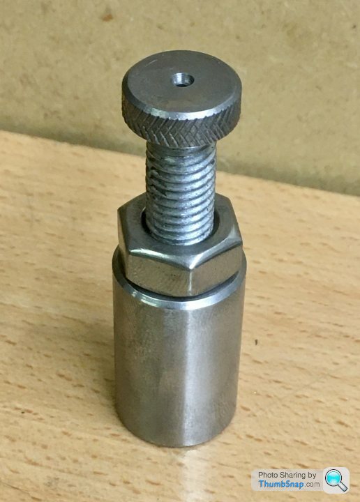
                Didn’t do much on the engine yesterday, but made a small machine jack (as per Martin's suggestion) to support the rather flexible eccentric strap end:

                I might make another, just in case I ever need two, and perhaps a couple of stepped, threaded studs so I can screw secure it into a T-slot if required.

                #497348
                Del Greco
                Participant
                  @delgreco45469

                  Looking great.

                  This was my first engine build and it was so satisfying seeing it move for the first time.

                  Looking forward to seeing more.

                  D

                  #497979
                  Dr_GMJN
                  Participant
                    @dr_gmjn
                    Posted by Del Greco on 23/09/2020 10:12:56:

                    Looking great.

                    This was my first engine build and it was so satisfying seeing it move for the first time.

                    Looking forward to seeing more.

                    D

                    Thanks!

                    #497980
                    Dr_GMJN
                    Participant
                      @dr_gmjn

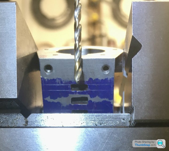
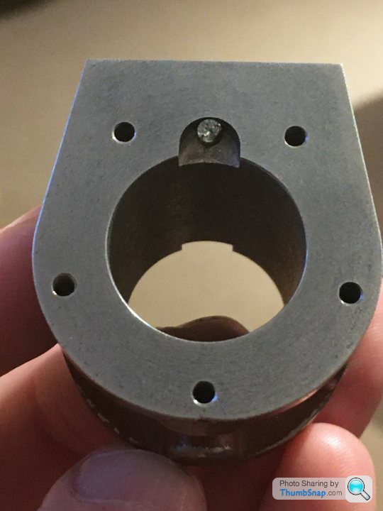
                      Not quite finished the eccentric strap yet – I’ve got to drill the oil hole, but can’t figure out how to do it:

                      There’s not enough clearance for a chuck. I was considering putting it at the other side of the stem, at 45 degrees to give myself room for the chuck, but Id like to know how to do it as per the drawing.

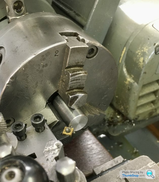
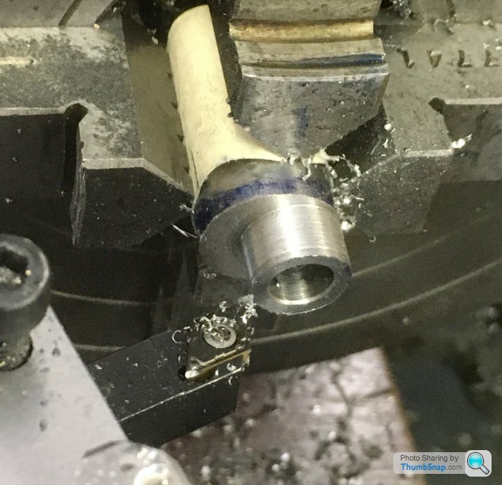
                      So I got on with the eccentric itself. The steel provided in the kit Is the correct o/d, so with that in mind, I faced it in the lathe:

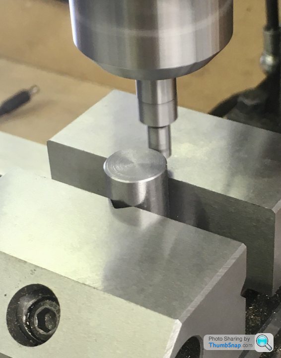
                      Then transferred to the mill and got the centre with the edge finder:

                      Then offset the x-axis by the eccentric throw, and centre drilled:

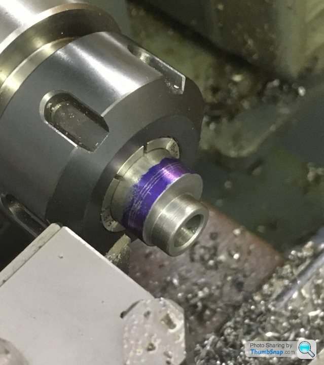
                      Then back to the lathe and set it in the 4-jaw chuck, centred on the offset hole:

                      Drilled and reamed to size:

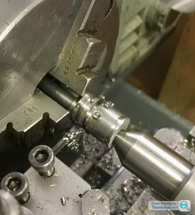
                      Then turned the spigot with intermittent cuts:

                      Marked out for the locating groove:

                      and then cut the groove with a ground down old HSS parting tool:

                      I started to part it off:

                      Then realised that because the hole is offset, it would break through at one side, and the process wouldn’t work. So I removed from the chuck and centered it on the hole again, meaning intermittent cuts for parting off:

                      It worked ok, but I found this material very difficult to work with . It seemed very tough, and turning tended to gouge the surface. I cleaned it up by making a wooden block and coating the face with SiC, and abraded the marks out by turning. A bit like lapping, but on the face.

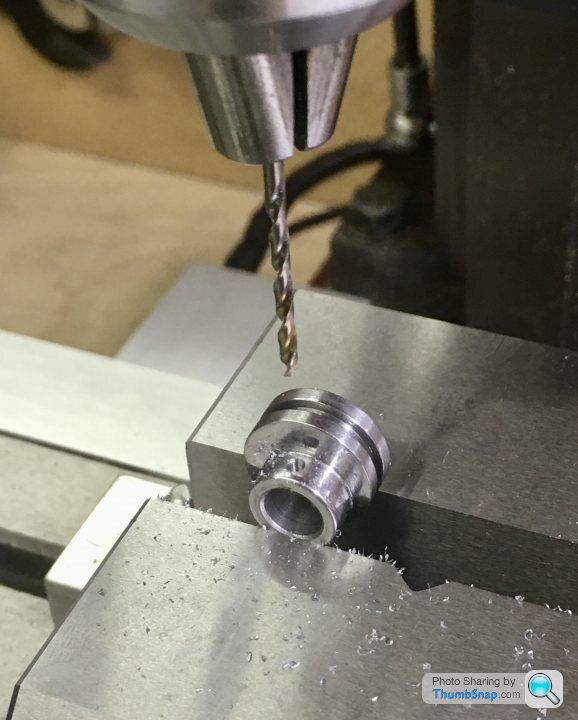
                      Finally, the screw hole. I set it up on the mill, getting the high point with a finger gauge:

                      Then drilled and tapped without any issue:

                      Finished, although it is a bit crunchy when rotated in the strap. No idea why.

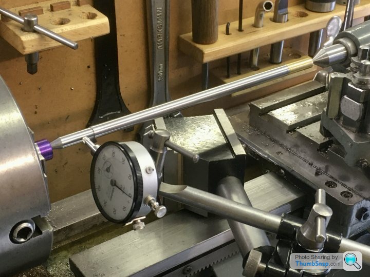
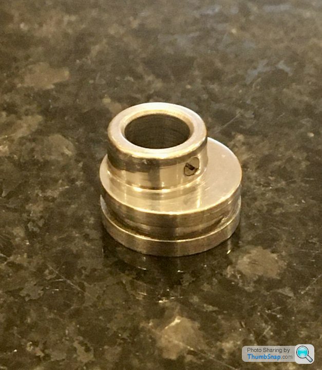
                      Also tidied up a few loose ends, like making an expanding mandrel and facing the main bearing external faces to length:

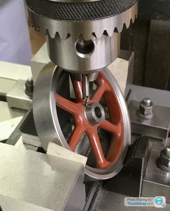
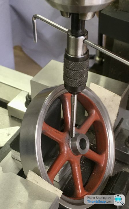
                      Again using the mandrel, facing the flywheel bosses to length, then mounting on the mill and drilling and tapping the screw hole:

                      And finally, machining the eccentric strap stepped locating bolt:

                      Not the best fit in the groove -a bit loose – but I found it difficult to get it right. Might have another go at that sometime.

                      #497983
                      JasonB
                      Moderator
                        @jasonb

                        The ideal thing to do the oil hole with is a long series ctr drill, I have an 1/8" x 3" long one which would be just right.

                        Failing that you can do it at a slight angle to get clearance or make a simple extension for an existing ctr drill by drilling a hole in some rod and using a drop of loctite to retain it.

                        #497998
                        Dr_GMJN
                        Participant
                          @dr_gmjn
                          Posted by JasonB on 26/09/2020 16:58:52:

                          The ideal thing to do the oil hole with is a long series ctr drill, I have an 1/8" x 3" long one which would be just right.

                          Failing that you can do it at a slight angle to get clearance or make a simple extension for an existing ctr drill by drilling a hole in some rod and using a drop of loctite to retain it.

                          Thanks, I'll try and get hold of a long series center drill then. The smallest one I have only just fits, making sleeving it impossible.

                          Re. the eccentric strap locating bolt – even though I've got clearance on teh groove, it still picks up occasionally. I wonder if it would be better made of brass, rather than steel-on-steel as it is now. It seems pretty smooth without the pin in place.

                          Cheers.

                          #497999
                          JasonB
                          Moderator
                            @jasonb

                            It's unlikely to pick up and gall so I would leave as it is, a small amount of play won't hurt.

                            #498415
                            Dr_GMJN
                            Participant
                              @dr_gmjn

                              Today I re-visited the cylinder, and made some progress with the steam ports.

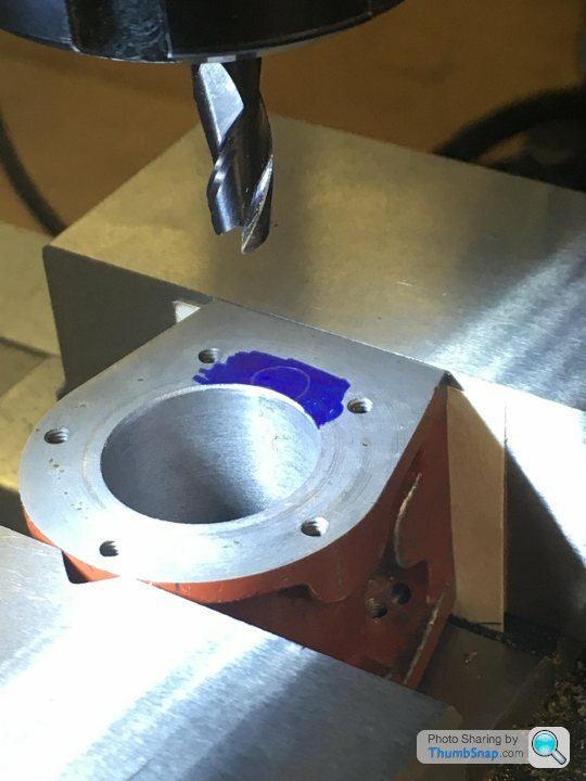
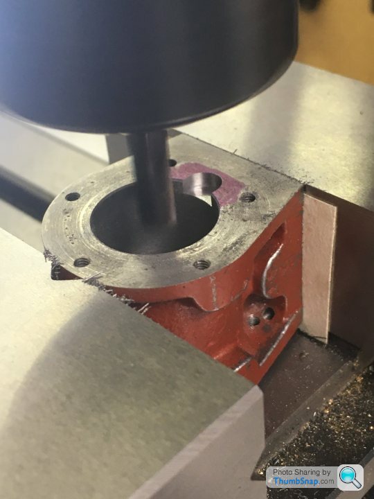
                              First off, the pockets adjacent to the cylinder. A depth and diameter is given, but no centre location. I used a 6mm milling cutter, moved to marked-out arcs defined by the gasket cut-outs:

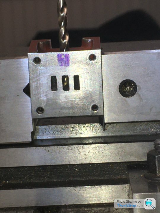
                              Then the exhaust drilling, to measured dimensions from the drawing. I marked out the projected position of the cast-in ports as a double check. Luckily the drill broke through the back of the port perfectly:

                              Then opened up the hole for a few mm, and tapped for the exhaust pipe fitting:

                              So that one turned out ok:

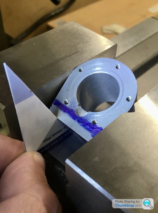
                              Then the tricky angled ones I’ve been putting off for a while. I started by extending all the port lines to the edge of the casting, and effectively drawing the positions of the ports on the side using the projected lines and measured depths. I then got the tilt angle using a protractor, and made a setting jig from an old plastic card (26 degrees):

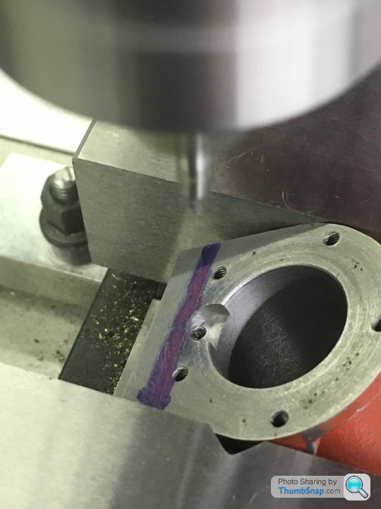
                              The machined port face was located against the gap in the vice bed, ensuring it was square. Then a centre drill was used to start the hole dead in the corner of the milled port:

                              With the dro zeroed, I moved the casting so I could set the z-stop such that any error wouldn’t result in breaking into the exhaust port, giving me a chance to correct things if necessary:

                              Then moved back to x-zero and drilled. It broke through bang in the corner of the port, as did the other side. Which was nice:

                              Next will be the insulation jacket securing holes, and the drain cock holes, but I’m waiting for a tap for those.

                              #498423
                              JasonB
                              Moderator
                                @jasonb

                                This is one of the few occasions when I would suggest drilling the cleading first and then spotting through the hole positions onto the cylinder or simply clamp the cleading around the cylinder and drill tapping size right though both before tapping the casting and opening up the other holes.

                                #498426
                                Dr_GMJN
                                Participant
                                  @dr_gmjn

                                  Thanks Jason – yes, only this morning I experimented by wrapping the cladding around the cylinder to do just that – hold it in place and drill pilot holes before springing the cladding off and drilling/tapping as appropriate. Then secure through the just tapped holes, re-orientate, and repeat the process.

                                  Didn't you say to use a smaller drill than tapping diameter where it breaks through to the cylinder for the drain cocks though – about 2mm IIRC? I want to do this before lapping, so that I can then make the piston assembly. I need to get it in the right order…

                                  Of course I also need to mill the O/D of the casting a bit using the rod-through-the-hole method you suggested a long time ago, in order to get the cladding to be a perfect fit under the cylinder cap overhangs. I also want it a flush fit to the valve chest – I machined that at the time to have the correct step.

                                  #498542
                                  Dr_GMJN
                                  Participant
                                    @dr_gmjn

                                    So today I tried to mill the outer cylinder concentric with the upper cylinder, using a method suggested here on the forum. This involved positioning a rod in the bore, putting it in the vice and milling a series of flats all around:

                                    I might have misunderstood the method, but I must admit I found it hard to position correctly – it was easy to get it into a position where the o/d wasn’t at its lowest point relative to the cutter. This culminated in it grabbing, and damaging the casting:

                                    Maybe it wasn’t orientated right, and I guess the vice should have been tighter, but either way it’s not a process I was particularly happy with.

                                    Anyway, luckily the damage was only cosmetic, and some epoxy metal and flatting and re-priming (for the next stages of marking out) resulted in the desired outcome, ie a consistent step to the end caps:

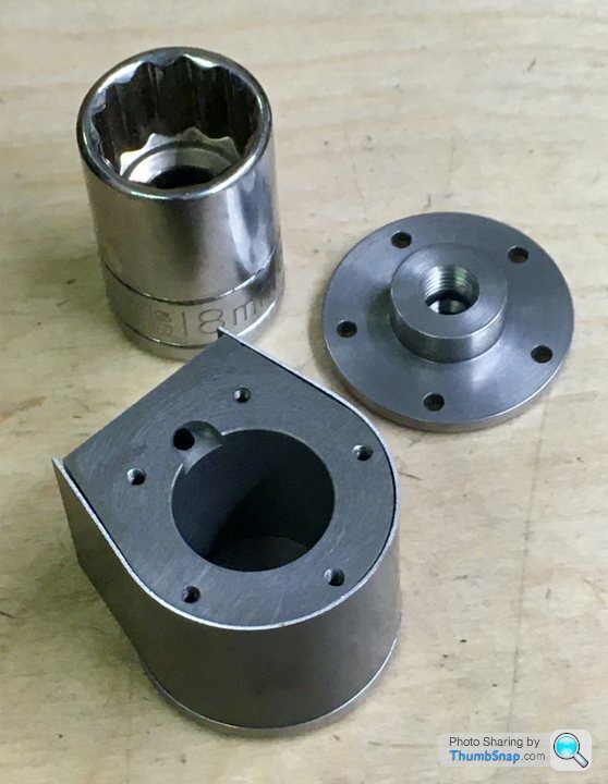
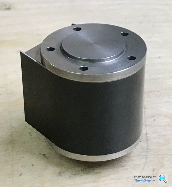
                                    I profiled the cladding using an 18mm socket, and test fitted it. It still needs trimming a bit:

                                    But so far, so good:

                                    Not sure if the cladding is some kind of anodised metal, but the finish is slightly flawed at one point. I might spray it satin black in the end.

                                    Also painted the box bed and screwed it to the wooden base:

                                    #498565
                                    JasonB
                                    Moderator
                                      @jasonb

                                      Yes you can use 1/16" or 1.5mm holes to drill the last couple of mm.

                                      It is anodised

                                      #498572
                                      Dr_GMJN
                                      Participant
                                        @dr_gmjn

                                        Ok.

                                        Are the holes in the cladding for the exhaust and drain cocks meant to fit around the parts? The exhaust in particular would appear to want to distort the cladding when tightened, because it’s at an angle to the surface. Also the drain cocks fit to a curved surface – should the seats be spot-faced and clearance holes made?

                                        Thanks.

                                        #498615
                                        geoff walker 1
                                        Participant
                                          @geoffwalker1

                                          I think you would to cut a channel for the exhaust port. If you try to distort the cladding when you tighten up the exhaust the cladding will just buckle.

                                          Is the cladding aluminium? If yes I am left wondering why the anodising did not crack when you formed the curve. What gauge is it, can you put a Mike on it to find out, I'd be interested to know.

                                          Also can you give more details about how you formed the curve. Was it as simple as you make sound to get such a neat curve, no clamping involved?

                                          Thanks geoff.

                                          Great work doc, once again I admire your attention to detail

                                          #498629
                                          Dr_GMJN
                                          Participant
                                            @dr_gmjn
                                            Posted by geoff walker 1 on 30/09/2020 11:38:14:

                                            I think you would to cut a channel for the exhaust port. If you try to distort the cladding when you tighten up the exhaust the cladding will just buckle.

                                            Is the cladding aluminium? If yes I am left wondering why the anodising did not crack when you formed the curve. What gauge is it, can you put a Mike on it to find out, I'd be interested to know.

                                            Also can you give more details about how you formed the curve. Was it as simple as you make sound to get such a neat curve, no clamping involved?

                                            Thanks geoff.

                                            Great work doc, once again I admire your attention to detail

                                            Cheers Geoff,

                                            Yes, it's aluminium, about 0.5 mm thick. The coating is extremely thin, to the extent that it fades away in certain areas, so it's unlikely to crack.

                                            Initially I just wrapped it around the casting by hand, forming it around the block with my thumbs, while making sure it wasn't skewed. There was some spring-back, so it needed over-bending slightly. I found that gently forming it around the socket (again by hand) eventually gave it the correct radius. Obviously I didn't go further than the straight edges where it tangents back to the valve block.

                                            The drilling may, or may not work out, but I kind of see it as a challenge to get it fitted properly without damaging the coating…

                                            #498631
                                            JasonB
                                            Moderator
                                              @jasonb

                                              A step drill is handy for cutting clearance holes for drain cocks

                                              #498632
                                              Dominic Bramley
                                              Participant
                                                @dominicbramley60728

                                                I finished my 10V earlier this year, and the cladding was the only part I managed to scrap. My mistake was to drill the holes as per the dimensions on the drawing and not having the presence of mind to remember that the (already drilled) exhaust port on the cylinder was not dimensioned. Still – at least it was an easy decision to chuck it in the bin when the holes didn't line up!

                                                Second time I measured from the job and using a 1/8 BMS drilling jig, as per Harold Hall's instructions, produced nice clean holes.

                                                For the drain cocks I spotted the holes and drilled clearance. For the exhaust port I drilled 1/4 and turned the exhaust pipe out of hex stock to produce a tube with a nut part way along it – just a little further up from the end of the thread. The exhaust pipe could then be screwed into the cylinder and tightened up without the nut crushing the cladding. Not sure if this is the "correct" solution – but looks Ok to me.

                                                Dom

                                                #498656
                                                Dr_GMJN
                                                Participant
                                                  @dr_gmjn

                                                  Thanks both – I’ll get a step drill from Arc.

                                                  Dom – I might steal your idea for the exhaust. I considered doing something similar, but with some shallow flats milled on some brass tube, with the end threaded.

                                                  Could you by any chance post a picture of your 10v?

                                                  Thanks.

                                                  #498658
                                                  Dominic Bramley
                                                  Participant
                                                    @dominicbramley60728

                                                    I don't have any pictures to hand just now – but here is a video of its first run on steam that gives a pretty good view of the exhaust. I threaded the other end of the tube also to connect to the elbow connector.

                                                    https://www.youtube.com/watch?v=xCclavQAQjA

                                                    Very satisfying when they run for the first time! It has run in since and can run quite slowly now.

                                                    The boiler is the ME vertical boiler which was serialised in the magazine last year and was also fun to make!

                                                    Regards

                                                    Dom

                                                    Edited By Dominic Bramley on 30/09/2020 16:04:29

                                                    #498719
                                                    Dr_GMJN
                                                    Participant
                                                      @dr_gmjn
                                                      Posted by Dominic Bramley on 30/09/2020 16:03:42:

                                                      I don't have any pictures to hand just now – but here is a video of its first run on steam that gives a pretty good view of the exhaust. I threaded the other end of the tube also to connect to the elbow connector.

                                                      **LINK**

                                                      Very satisfying when they run for the first time! It has run in since and can run quite slowly now.

                                                      The boiler is the ME vertical boiler which was serialised in the magazine last year and was also fun to make!

                                                      Regards

                                                      Dom

                                                      Edited By Dominic Bramley on 30/09/2020 16:04:29

                                                      Thanks Dom – it looks like a very nice 10V build, and setup with the boiler too.

                                                    Viewing 25 posts - 276 through 300 (of 385 total)
                                                    • Please log in to reply to this topic. Registering is free and easy using the links on the menu at the top of this page.

                                                    Advert

                                                    Latest Replies

                                                    Viewing 25 topics - 1 through 25 (of 25 total)
                                                    Viewing 25 topics - 1 through 25 (of 25 total)

                                                    View full reply list.

                                                    Advert

                                                    Newsletter Sign-up