Stuart 10V Build Log – Complete Beginner…

Advert

Stuart 10V Build Log – Complete Beginner…

Home Forums Work In Progress and completed items Stuart 10V Build Log – Complete Beginner…

Viewing 25 posts - 251 through 275 (of 385 total)
  • Author
    Posts
  • #495485
    Dr_GMJN
    Participant
      @dr_gmjn

      So…crank webs part deux. The spare material from Stuart Models is £10.46 (delivered) for a 2” length. My local materials company supplied my 1/2 metre for £1.20. I’ll not comment further on that,

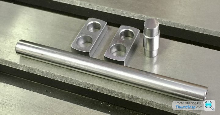
      First job – Loctite two pieces together:

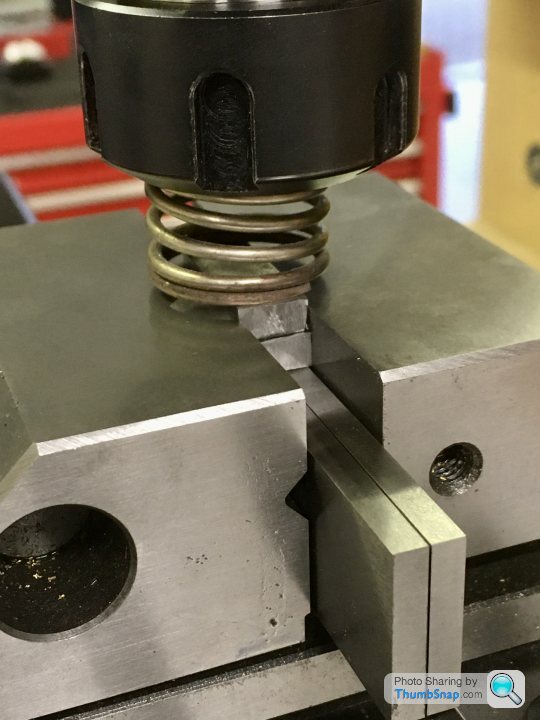
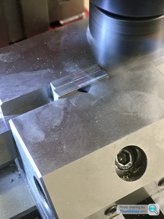
      Then fly-cut the edges to clean them up a fraction to be perfectly flat and parallel:

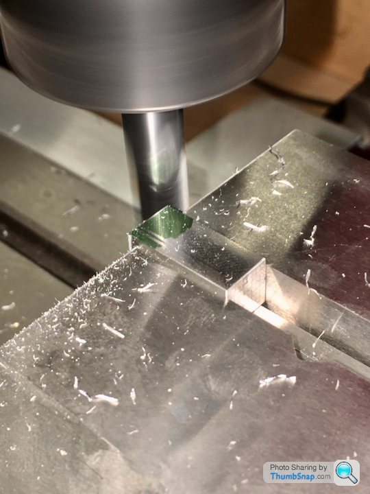
      Mill the ends to be square:

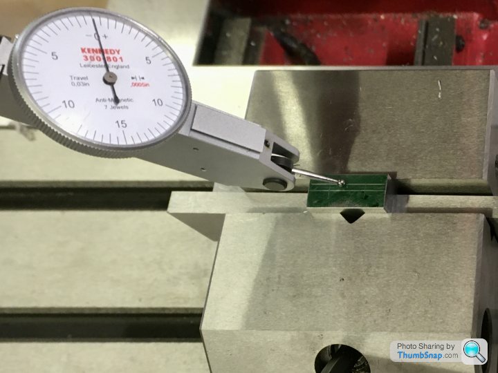
      Mark out, then put in the vice and check for level:

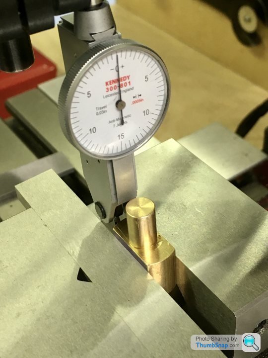
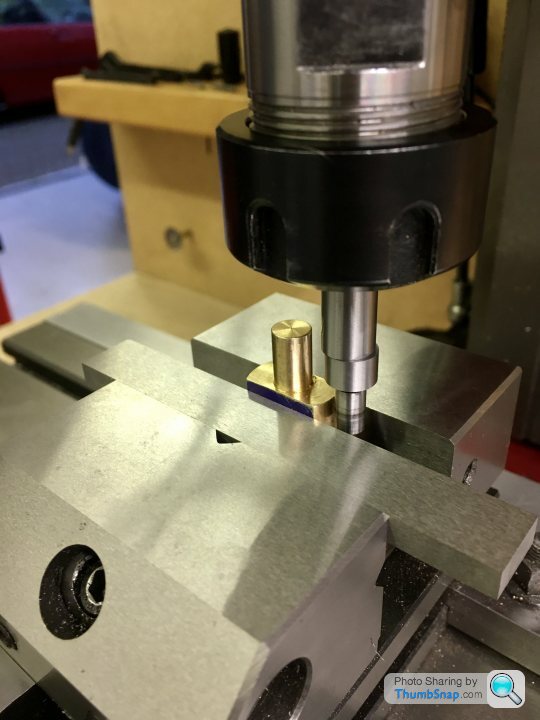
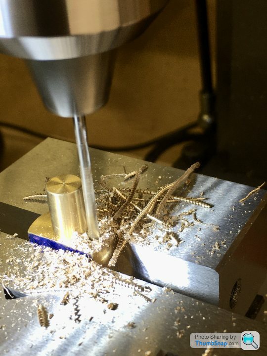
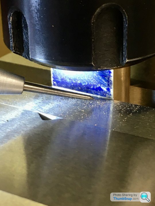
      Co-ordinate drill/ream the holes, having first used the edge finder to get the datums. This time I used the marking out as a double-check:

      Then used the nut and bolt method to turn the end radii:

      Then machined the main shaft. Not sure why there’s a hole in one end, but it’s on the drawing:

      Main components ready for assembly:

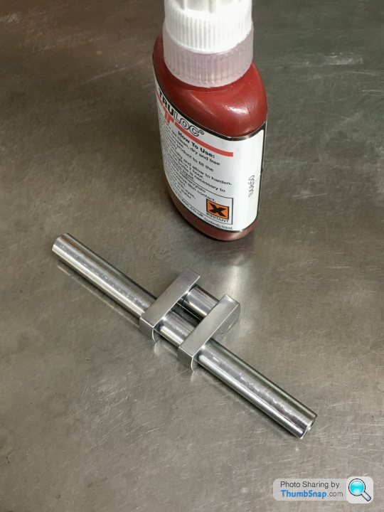
      And Loctited together:

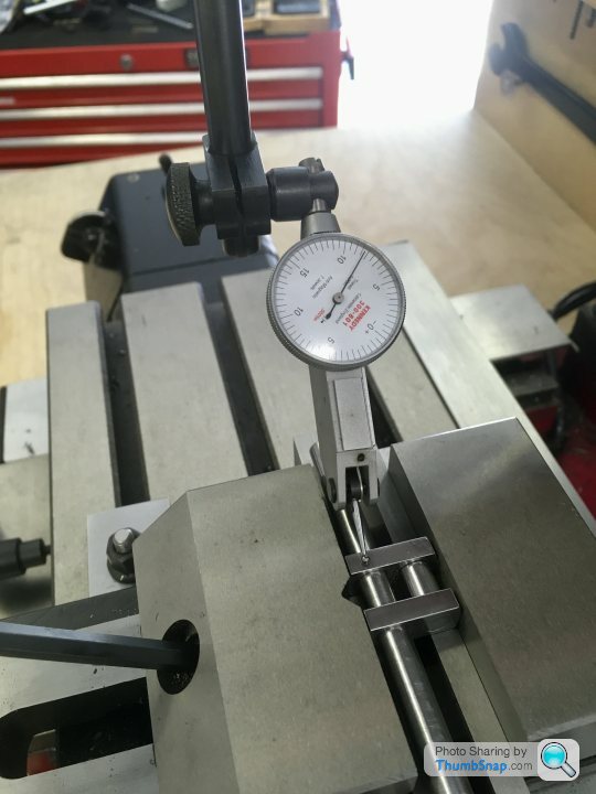
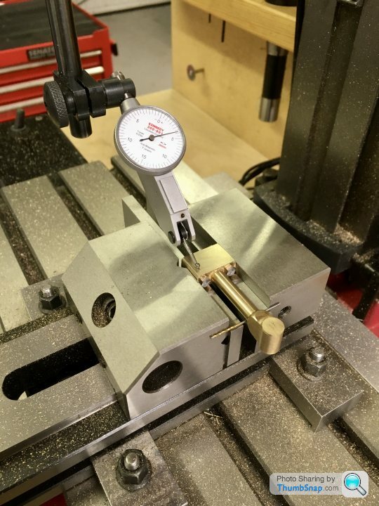
      Now re-set in the vice and check for level:

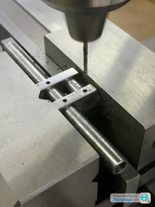
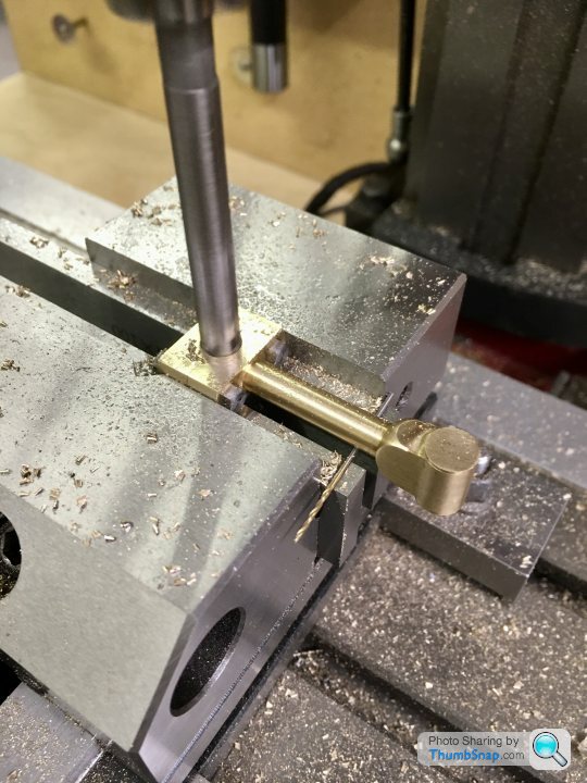
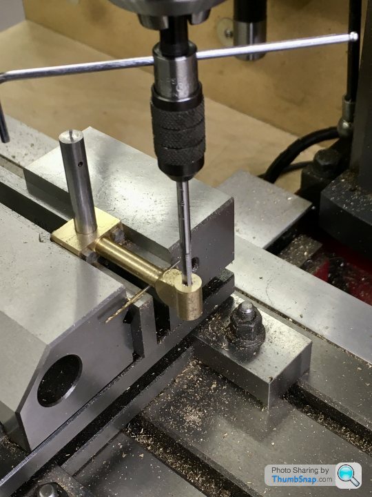
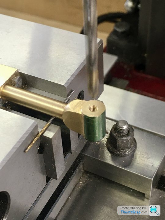
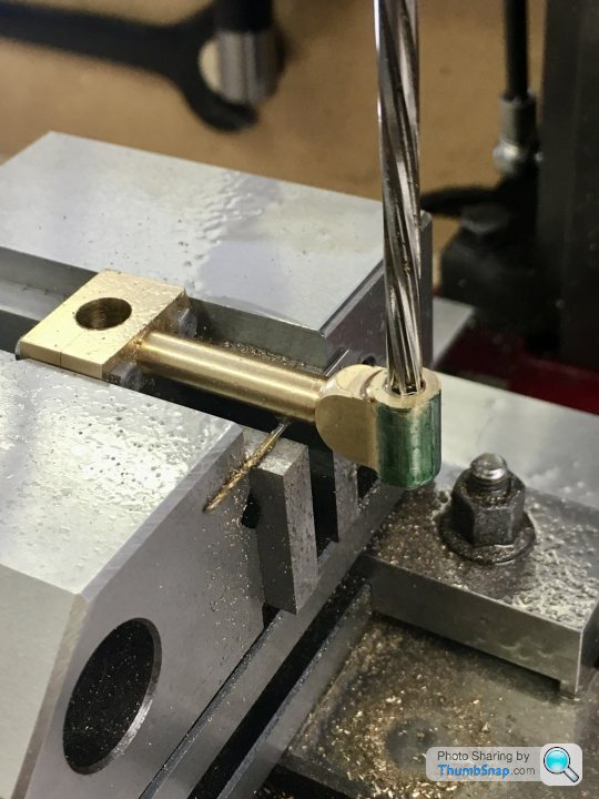
      And co-ordinate drilled the pin holes:

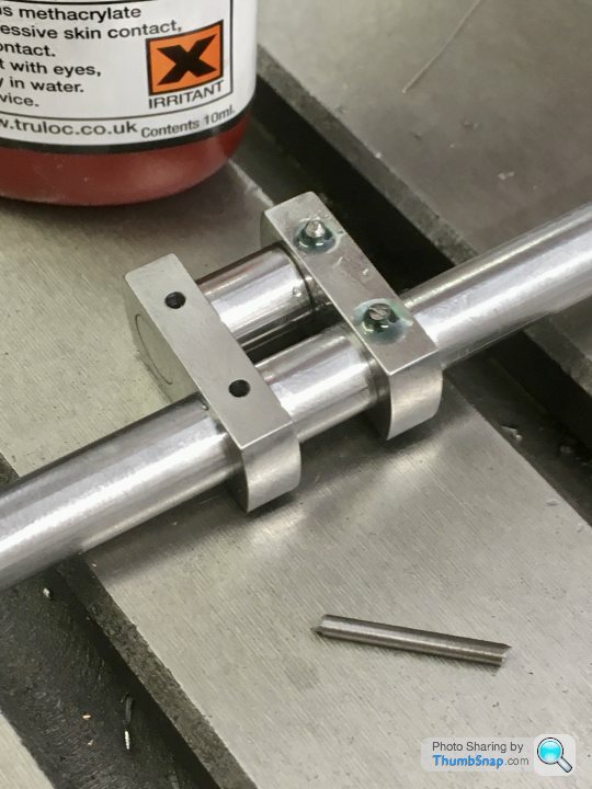
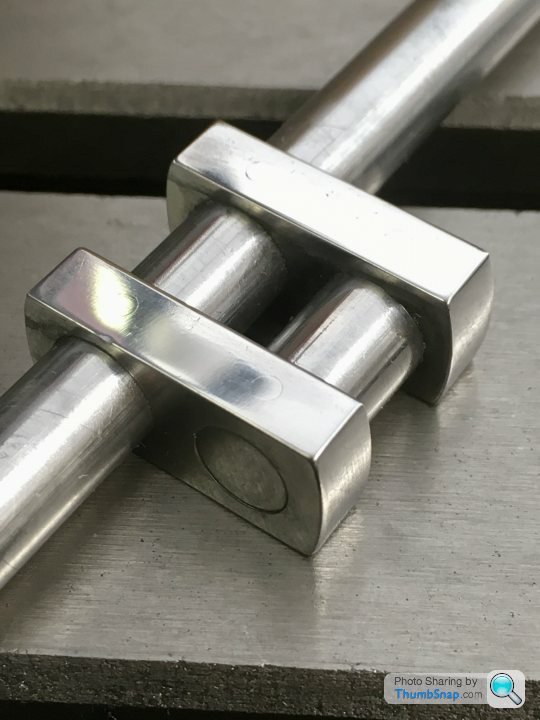
      Tapped the Loctite-coated pins in with a hammer, and flatted and polished back:

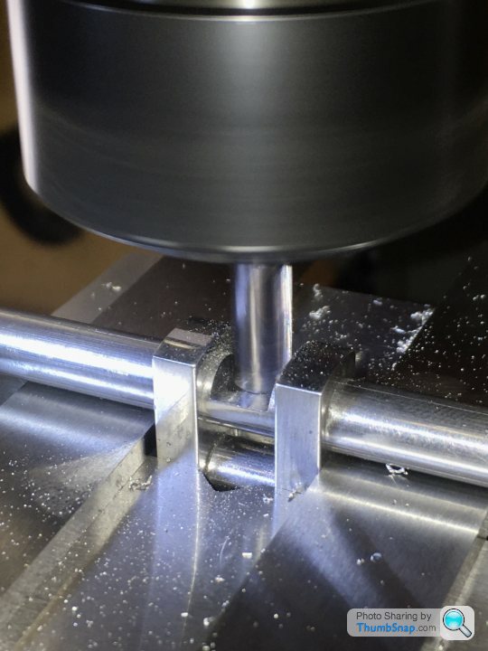
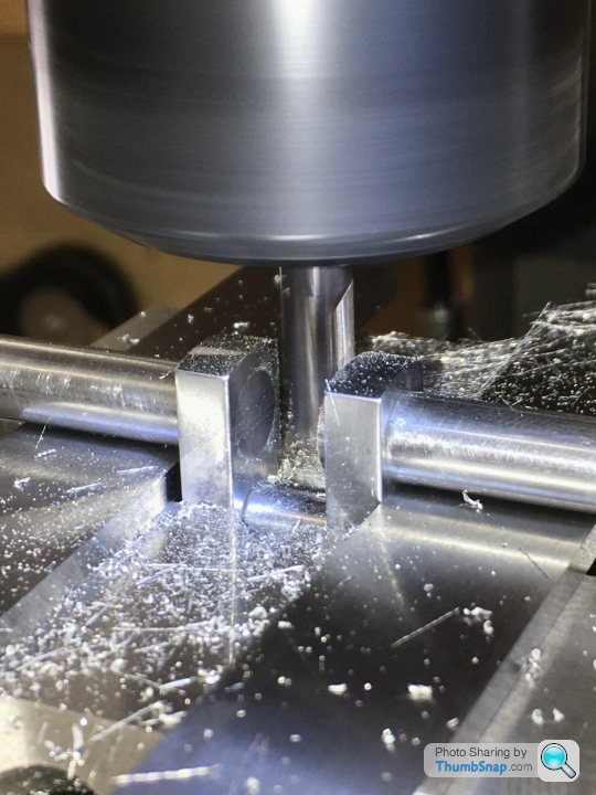
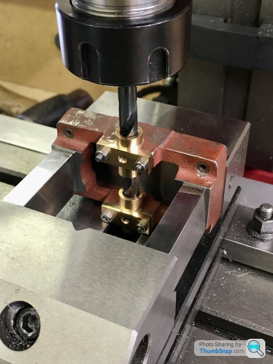
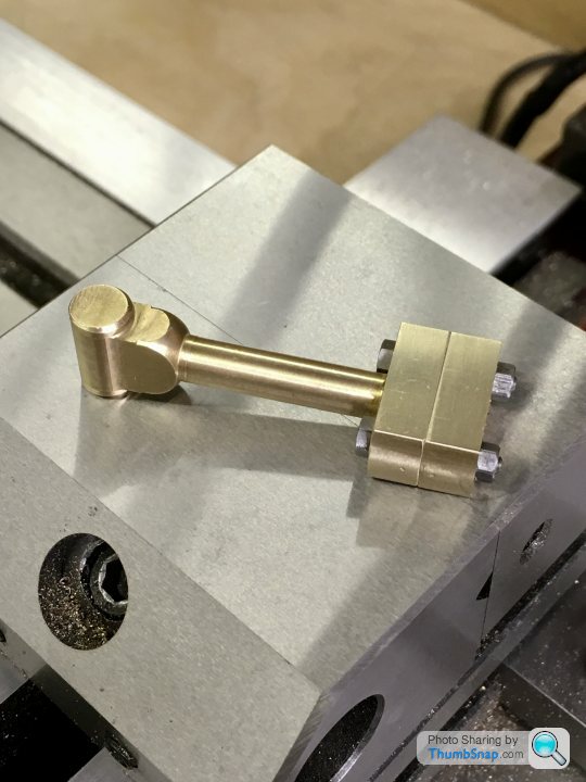
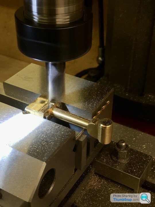
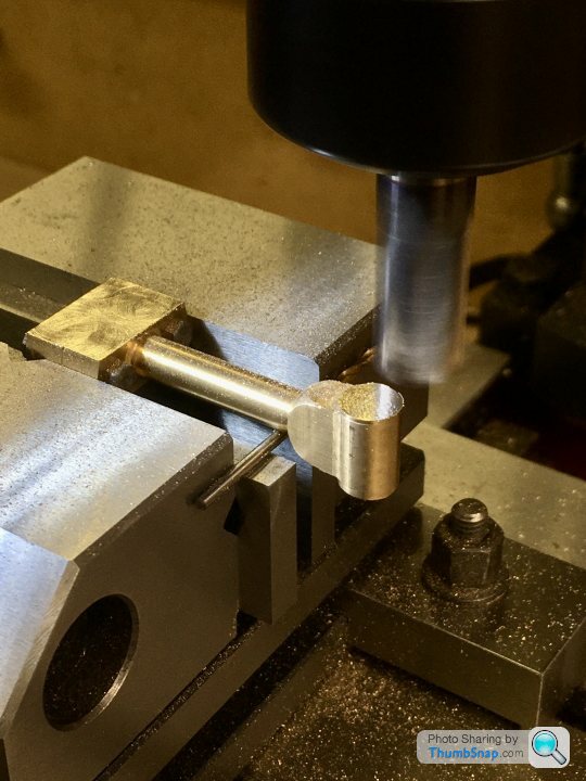
      Then put back in the vice, dropped onto a pair of parallels. The sacrificial part of the main shaft was then carefully milled away:

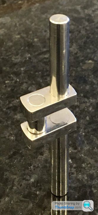
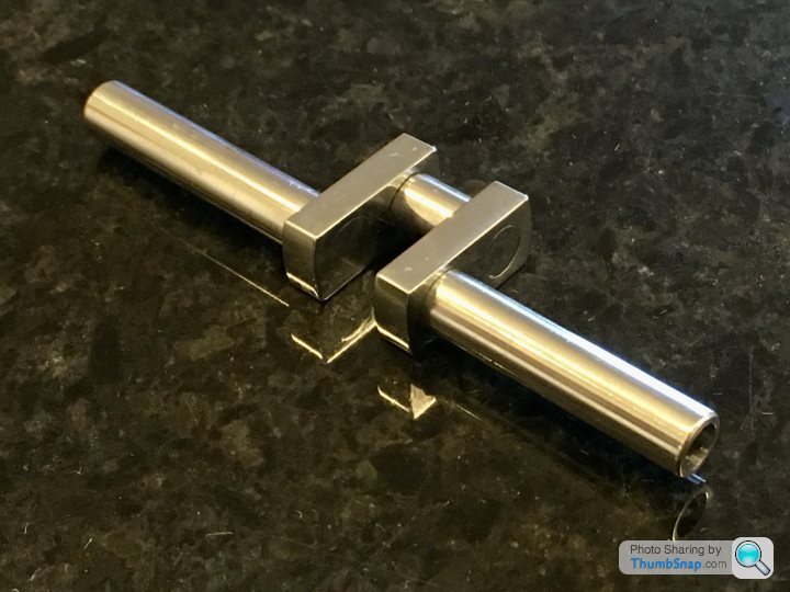
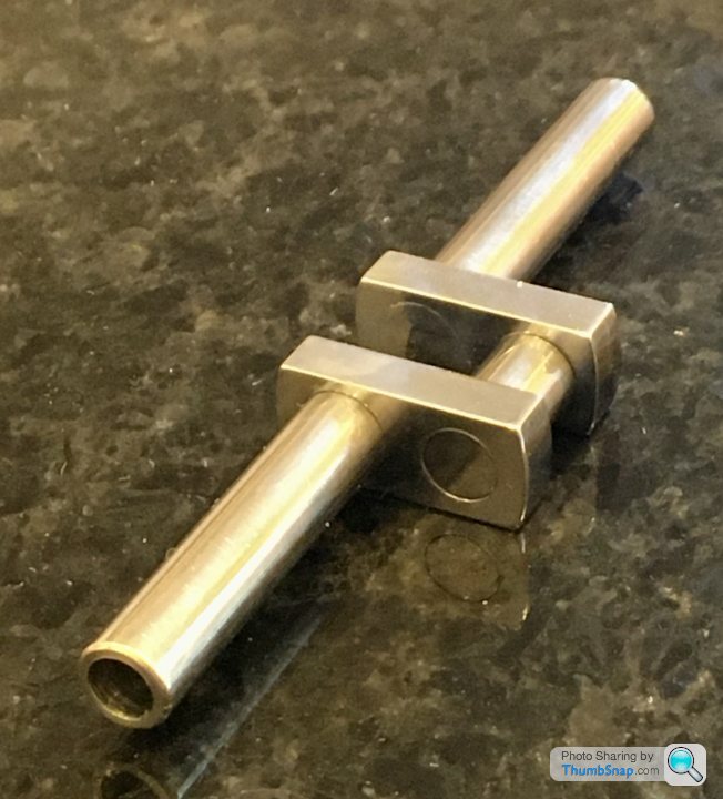
      That completed the crankshaft:

      So second time around it worked fine.

      Advert
      #495486
      Dr_GMJN
      Participant
        @dr_gmjn

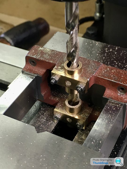
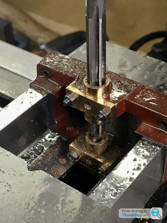
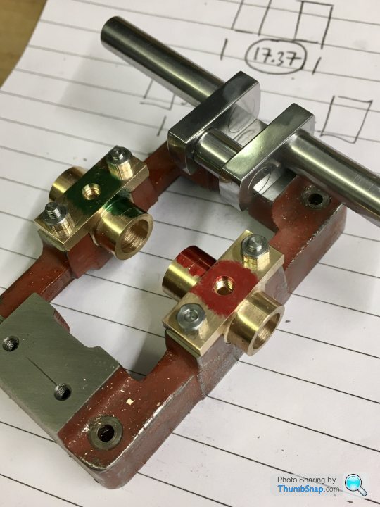
        Then straight on to fitting the crankshaft to the bearings.

        Began by aligning the assembled bearings into the vice using the drill I used to bore them undersized:

        Then substituted it with the pre-ream drill:

        Then the reamer:

        Then sized the bearing thrust faces by trial and error turning in the lathe. I should probably have used an expanding mandrel, but the collet chuck seemed to work well enough. The crank pin is now central in the sole plate (let’s hope it’s also aligned correctly under the cylinder bore axis):

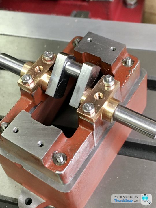
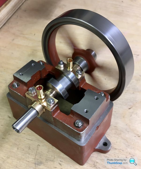
        It all fitted together well enough:

        No side play, and after test-fitting the flywheel, it spins as smooth as silk:

        I’m pretty satisfied with today’s progress.

        #495516
        JasonB
        Moderator
          @jasonb

          Some good progress over the last few days, I seem to recall that the hole is so that a smaller shaft can be soldered/Loctited in to extend the shaft should you want to fit a boiler feed pump or coupling for a prop shaft.

          #495526
          Dr_GMJN
          Participant
            @dr_gmjn
            Posted by JasonB on 13/09/2020 07:02:08:

            Some good progress over the last few days, I seem to recall that the hole is so that a smaller shaft can be soldered/Loctited in to extend the shaft should you want to fit a boiler feed pump or coupling for a prop shaft.

            Thanks. OK so the shaft hole isn’t that important.

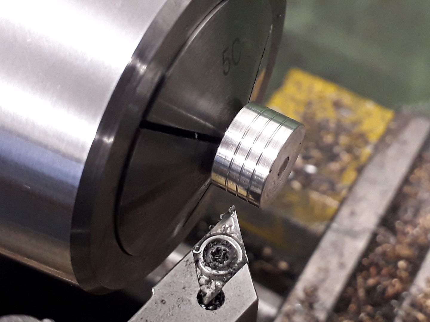
            I think I’ll need to turn some square cornered features in the piston (oil retaining grooves), and around the eccentric (for a locating pin) Are specific tools for this available? I’ve got a parting tool which I guess is similar, but it’s too wide for these jobs I think.

            Cheers.

            #495528
            Martin Connelly
            Participant
              @martinconnelly55370

              A good reason to keep pieces of broken tools is to use as material for home ground grooving tools. A damaged milling cutter of reasonable size can often be ground to leave give a 1mm (or less) wide grooving tool, they usually don't need to stick out much. The other option is to have some HSS blanks of different sizes handy to grind into a suitable tool. Making a suitable holder is also a simple exercise.

              Here's an earlier thread on this subject

              Martin C

              Link added

              Edited By Martin Connelly on 13/09/2020 09:21:44

              #495538
              JasonB
              Moderator
                @jasonb

                Piston oil groove son this engine are usually just shallow vee shaped ones, if you mappen to have a threading tool about that will do or even a DCMT or DCGT insert with a small end radiu will do just fine.

                The groove for the eccentric would be done with a narrow parting type tool which can either ground from a bit of HSS or narrow ones can be bought, 1.5mm wide are readily available from the ME suppliers quite cheaply or you can pay a lot more for insert grooving tools. that go down very thin and have a range of size inserts

                #496235
                Dr_GMJN
                Participant
                  @dr_gmjn

                  I'm now part way through machining the connecting rod. I need to hold the big-end in the lathe chuck, to turn the cheek bosses. Would an expanding mandrel be OK for this, made from some spare crankshaft rod? I don't want to damage the reamed big end hole. I'd also use it to hold the main bearings, to finish machine their outer boss faces.

                  Thanks.

                  #496267
                  JasonB
                  Moderator
                    @jasonb

                    Yes, or you can turn a spigot onto the end of some bar and tap say M3 then retain conrod with screw and washer.

                    #496280
                    Dr_GMJN
                    Participant
                      @dr_gmjn
                      Posted by Dr_GMJN on 17/09/2020 07:48:06:

                      I'm now part way through machining the connecting rod. I need to hold the big-end in the lathe chuck, to turn the cheek bosses. Would an expanding mandrel be OK for this, made from some spare crankshaft rod? I don't want to damage the reamed big end hole. I'd also use it to hold the main bearings, to finish machine their outer boss faces.

                      Thanks.

                      Hmmm that might be better for the connecting rod – rather than a standard washer, I could turn some bar to the required o/d of the boss, and use it as a guide for turning the diameter as well as a retainer.

                      Will need an expanding mandrel for the bearing blocks though.

                      Thanks for the suggetions.

                      #496293
                      Dr_GMJN
                      Participant
                        @dr_gmjn

                        One other question: The forked end of the connecting rod is threaded 5BA at one side, and a plain diameter (larger than 5BA, but can't remember the size) at the other, so that the slider pin can locate and be secured. The drawings call for the plain hole to be reamed, but I don't think there's enough room for the tapered part of the reamer to fully complete the hole, before it hits the smaller threaded side.

                        Question is, does it really need reaming? I'd have thought that so long as the pin in a good fit with no play, it wouldn't matter too much.

                        The only issue is possibly that the pin dimeter itself does need to be a good fit in the slider hole, and the slider hole perhaps needs reaming, making the pin size important. That would have a knock-on effect to the fork end.

                        Any thoughts? Thanks.

                        #496312
                        JasonB
                        Moderator
                          @jasonb

                          This is where machine reamers have their advantages as they don't have the taper like a hand reamer. You may be OK as you ideally want the pin a firm fit in the fork but a looser fit in the crosshead so the slightly smaller hole may be an advantage. You can always just open it out a touch by hand with a scraper, needle file or home made reamer.

                          #496334
                          Dr_GMJN
                          Participant
                            @dr_gmjn
                            Posted by JasonB on 17/09/2020 13:18:52:

                            This is where machine reamers have their advantages as they don't have the taper like a hand reamer. You may be OK as you ideally want the pin a firm fit in the fork but a looser fit in the crosshead so the slightly smaller hole may be an advantage. You can always just open it out a touch by hand with a scraper, needle file or home made reamer.

                            Thanks Jason, I wasn't aware of the different reamer types, so I just checked and mine is in fact a machine reamer. I had a look on the Dormer website, and no lead-in taper is shown for it, so there was probably no issue. I will use the reamer and estimate the depth I need to go – the fork centre isn't machined out yet. When I machine the pin, I can make it a fairly tight fit, which should also give me the opportunity to ream the slider and work the pin with some Autosol and oil (or whatever) until it's a perfect fit.

                            #496562
                            Dr_GMJN
                            Participant
                              @dr_gmjn

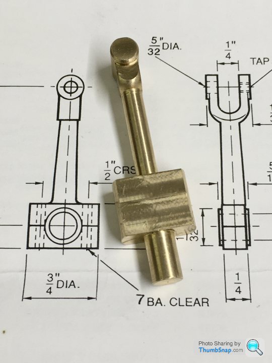
                              Connecting rod next. I believe it used to be supplied as a stamping, but now it’s a rough-machined item:

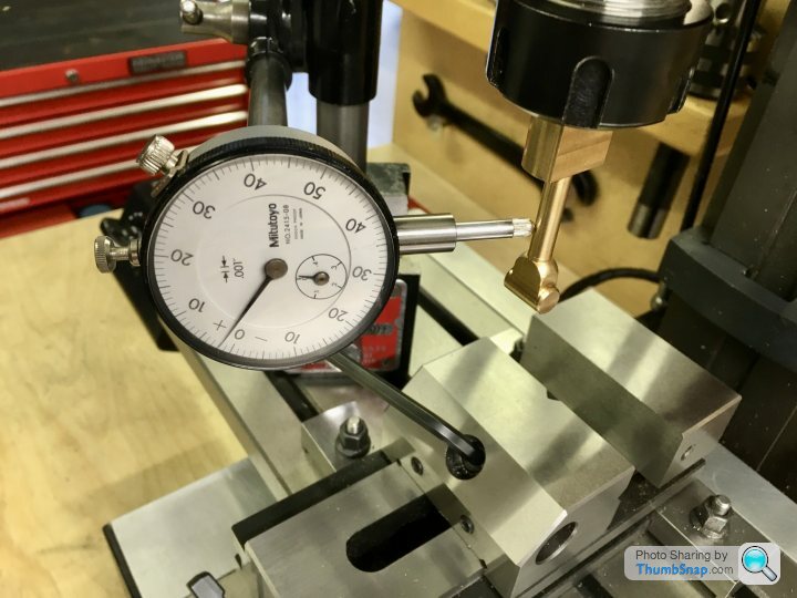
                              For some reason, it’s got a spigot on the back. I used it to locate in the mill collet, and then lowered into the vice in preparation for drilling the bolt holes. I clocked it up beforehand to check it was straight; it wasn’t bad, a few thou runout:

                              And again in the vice to check all the accessible surfaces were square:

                              I then used the edge finder to centre the spindle:

                              Then co-ordinate drilled the holes. I used a smaller drill than specified in order to get a tighter fit:

                              Then removed from the vice, marked out the split line, and the-fitted in the vice to check its level:

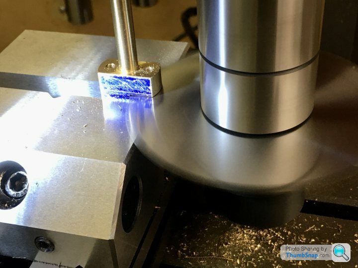
                              Then used the thin slitting saw to cut the lower block:

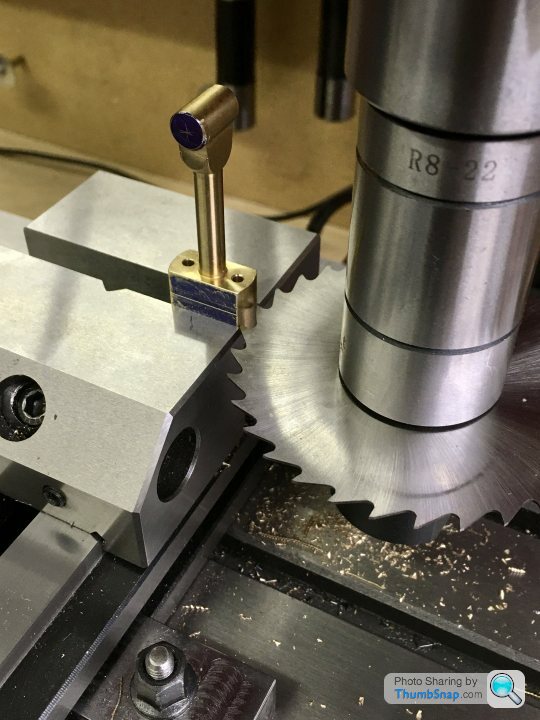
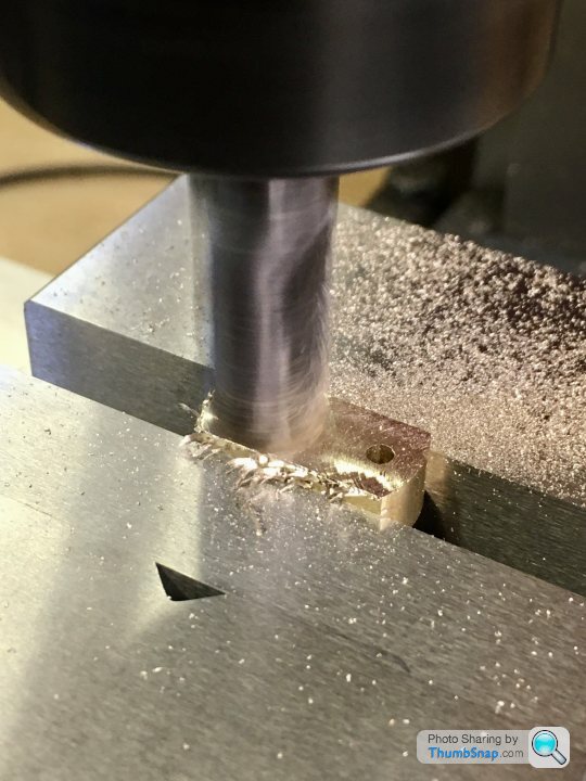
                              Then cleaned up the mating faces with an end mill:

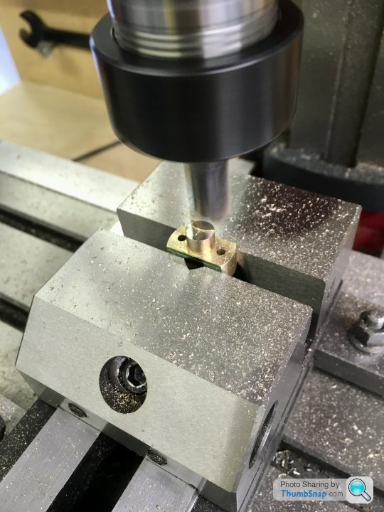
                              And removed the spigot from the lower block and milled to the correct depth:

                              Bolted together and Loctited, the sides were milled to the right thickness to fit between the crank webs:

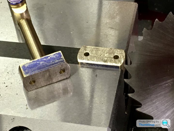
                              And the small end faces. A bit of vibration here, but I couldn’t think how else to hold it to drill bothe ends in the same setup:

                              Then double checked the main faces for flatness in two planes:

                              Then got the centre point for the crank pin hole bang on the cut line:

                              Drilled and reamed:

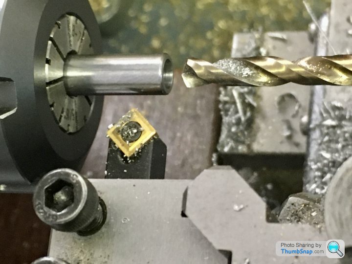
                              Then on to the small end. Through drilled and tapping to 5BA:

                              And in the same setup, drilled and reamed half way to pin size (removing the upper threads in the process):

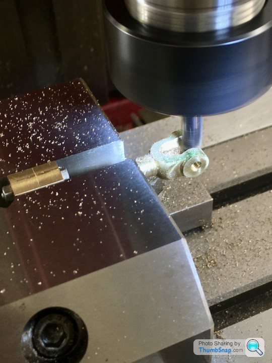
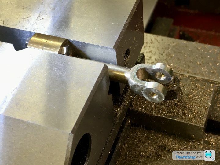
                              Next job was to measure and open out the forked end by milling:

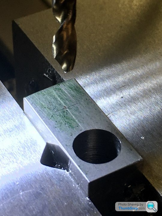
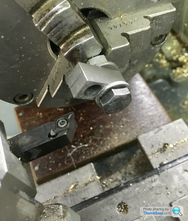
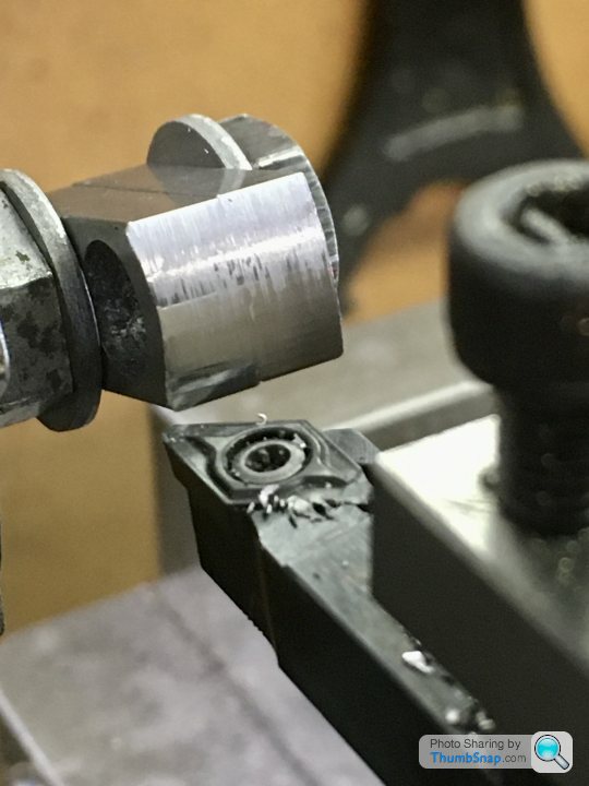
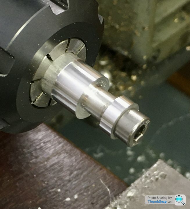
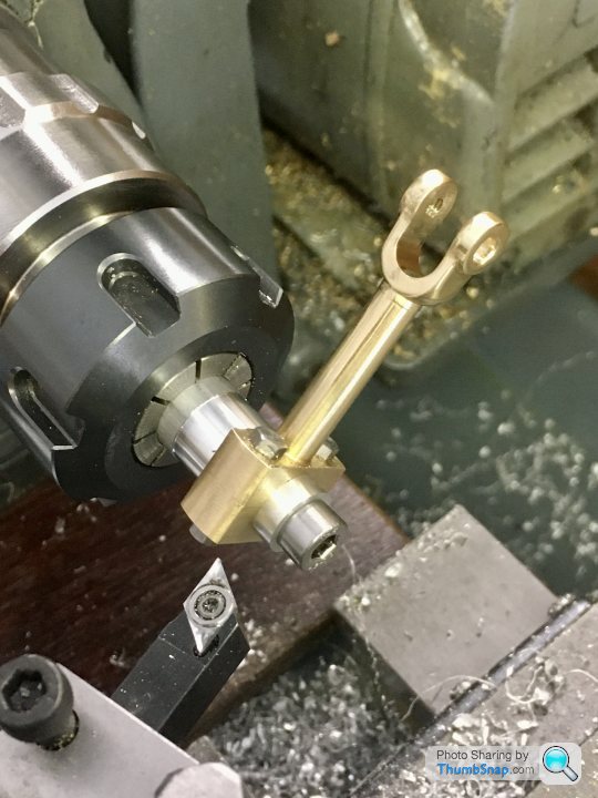
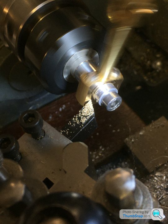
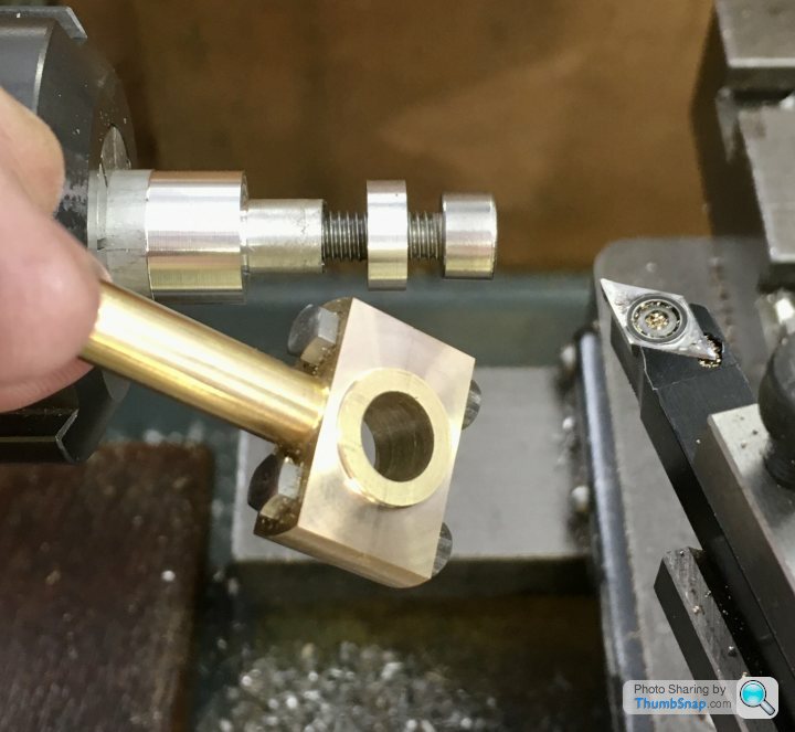
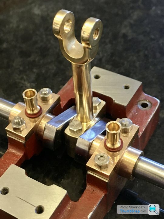
                              Final job was to machine the cheek bosses. I made a simple fixture out of aluminium (thanks for the idea Jason). The end boss is a clamp and a diameter reference:

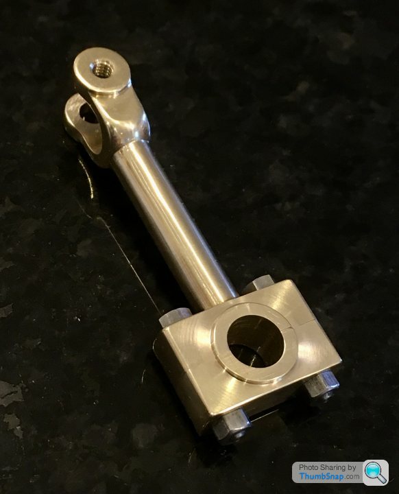
                              So after a quick polish, that’s another bit done:

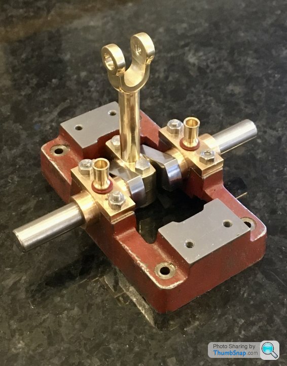
                              On assembly, there was a slight resistance to turning in a couple of spots, but working with a drop of light oil soon had it working smoothly with no side play at all:

                              The sides of the bearing block are very close to the sole plate, but are in fact under-sized to the drawing. The slider stamping the the forked end located around is also undersized slightly as supplied. Bit of a shame Because I could have narrowed the fork. It’s only a slight bit of play though, and I may well need it once assembled…
                              #496564
                              JasonB
                              Moderator
                                @jasonb

                                Looking good, The CNC machined part is a lot easier to work with than the old soft gun metal casting that was supplied which most people tended to bend while trying to mill out the fork. The spigot was to hold it by while taper turning the shaft.

                                #496595
                                Dr_GMJN
                                Participant
                                  @dr_gmjn
                                  Posted by JasonB on 18/09/2020 19:50:49:

                                  Looking good, The CNC machined part is a lot easier to work with than the old soft gun metal casting that was supplied which most people tended to bend while trying to mill out the fork. The spigot was to hold it by while taper turning the shaft.

                                  Thanks. I did wonder about tapering the shaft, but the Stuart book I have on building the 10v doesn’t mention it, and the images appear to show it parallel.

                                  I guess it would look better tapered. I’m in two minds about it – I don’t really want to mess about with the tailstock of my lathe at this point. Not sure if there’s an easy(er) method? Obviously it would have been simpler with the spigot, but the sides of the main bearing block appear to be machined circular anyway, so I could easily mount it in a split bush in the chuck.

                                  #496597
                                  Dr_GMJN
                                  Participant
                                    @dr_gmjn

                                    I wonder if I could turn a taper like that just by adjusting the compound slide? Might try it after getting a bit further with the piston and slider.

                                    #496631
                                    JasonB
                                    Moderator
                                      @jasonb

                                      It's a compound slide job, would have been easier if done before milling out the fork as you can use tailstock support

                                      #496641
                                      Dr_GMJN
                                      Participant
                                        @dr_gmjn
                                        Posted by JasonB on 19/09/2020 07:01:38:

                                        It's a compound slide job, would have been easier if done before milling out the fork as you can use tailstock support

                                        Yes, I was thinking to size a block of aluminium to fit in the fork, nip it together with a 5BA bolt and centre drill it.

                                        #496776
                                        Martin Connelly
                                        Participant
                                          @martinconnelly55370

                                          I think a few home made machine jacks would be of use to you. Nothing fancy, just a cylinder of some suitable material tapped through and a bolt with a smoothed off head. It will allow a far more substantial support and can be used with some top clamping to do jobs like the one where the work piece is supported by a small drill.

                                          Martin C

                                          #496783
                                          Dr_GMJN
                                          Participant
                                            @dr_gmjn
                                            Posted by Martin Connelly on 19/09/2020 20:26:12:

                                            I think a few home made machine jacks would be of use to you. Nothing fancy, just a cylinder of some suitable material tapped through and a bolt with a smoothed off head. It will allow a far more substantial support and can be used with some top clamping to do jobs like the one where the work piece is supported by a small drill.

                                            Martin C

                                            Yes, I was thinking that, I suppose I should make one for drilling the eccentric arm.
                                            In fact there are quite a few things I need to do or make that would make life easier:

                                            DROs for the lathe, or at least some settable dials.

                                            Thrust bearings on the lathe slide handles (not sure how to machine the holders with them removed though).

                                            Jacks.

                                            A spindle handle for threading in the lathe.

                                            A DTI holder to fit the lathe tool holder.

                                            I should have sorted these out before starting on the engine I suppose, but after fettling the milling machine it felt like enough was enough – I bought it to make the 10V, not to modify it and make tools.

                                            I’ll get around to doing it all before I start the next steam engine kit – hopefully next year if the Doncaster show is on (unlikely it seems).

                                            #496794
                                            Dr_GMJN
                                            Participant
                                              @dr_gmjn

                                              Another couple of questions about the eccentric strap:

                                              Does the large hole need reaming, or can I somehow set it on a faceplate and use a boring bar to get a fit on the eccentric?

                                              Also, the diagram shows a bolt with lock nuts through clearance holes through the split side of the strap. The two lock nuts look a bit clumsy. Is another option to clearance drill only the upper side of the split, thread the lower part of the split, and use only one nut to lock?

                                              Thanks.

                                              #496989
                                              Dr_GMJN
                                              Participant
                                                @dr_gmjn

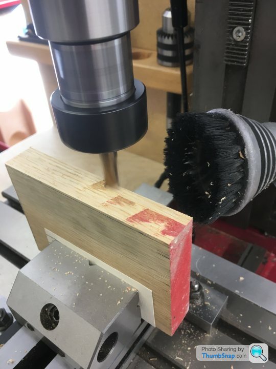
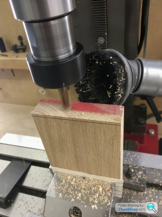
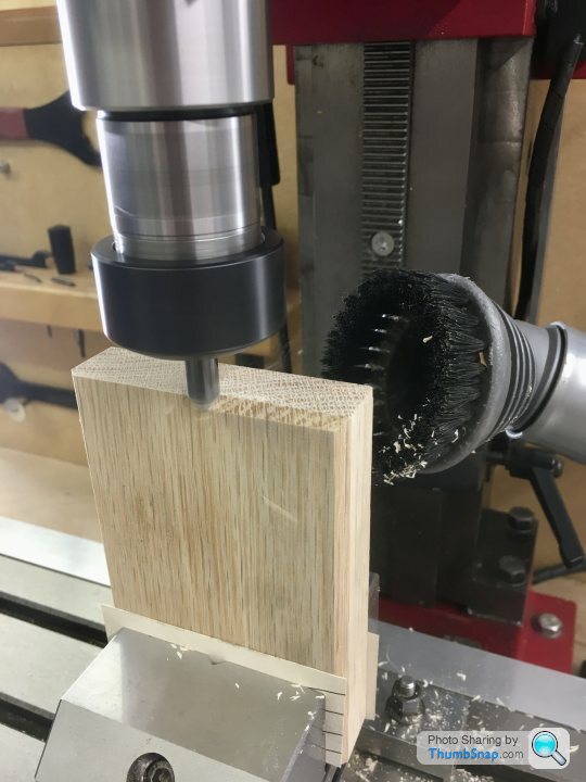
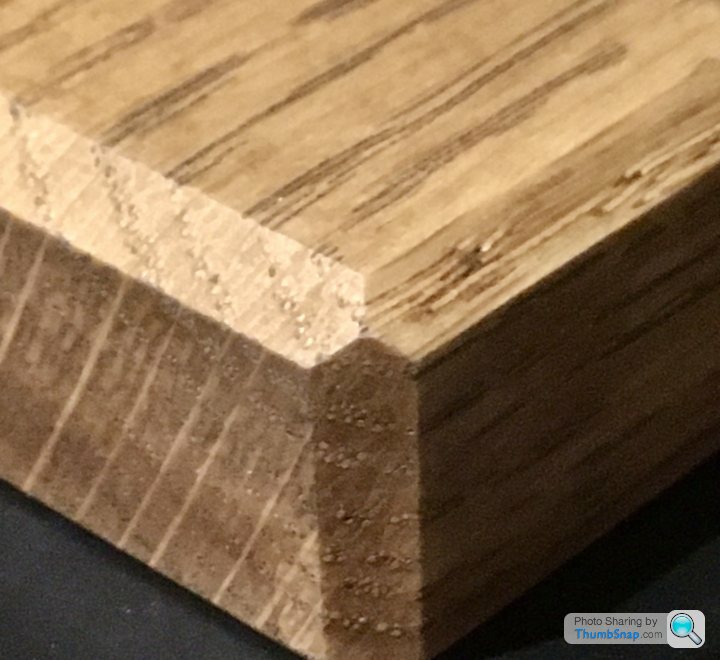
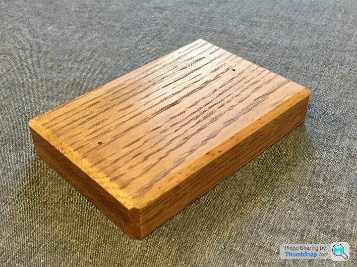
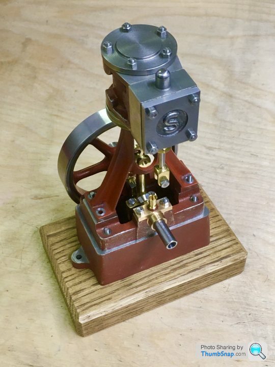
                                                Bit out of sequence, but made a base today out of some spare Oak and a spot of Briwax. I used one of the slot drills that I can't seem to use effectively on metal, and a woodworking router bit for the chamfers:

                                                I heard wood dust doesn’t do machine tools any good – something to do with silica or something in the wood. Anyway it won't be a regular thing, so I guess it's OK.

                                                #496990
                                                JasonB
                                                Moderator
                                                  @jasonb

                                                  Yes the strap can be bored on the lathe or if you have a boring head it could be done on the mill. Easier to sneak up on the size when using the lathe but easier to hold on the mill.

                                                  Yes tapping and a single lock nut will also work.

                                                  #496996
                                                  roy entwistle
                                                  Participant
                                                    @royentwistle24699

                                                    Just make sure you get rid of all Oak shavings from all tools.

                                                    #496997
                                                    Dr_GMJN
                                                    Participant
                                                      @dr_gmjn

                                                      Thanks guys.

                                                      Any tips for holding/centering the strap in the lathe for boring, and drilling the oil hole adjacent to the arm? I guess there is a danger of distorting the hole if I clamp it incorrectly.

                                                      I'm thinking of:

                                                      1) Milling the main faces and small end boss faces to the right thickness first.

                                                      2) Then mill the sides (next to the large hole).

                                                      3) Then drill the clamp & centering bolt holes and the oil hole – not sure how to do this, because the oil hole is right next to the arm.

                                                      4) Then bore the main hole – this is where I'm not sure how to hold it.

                                                      5) Then drill the small hole on the mill.

                                                      Thanks.

                                                    Viewing 25 posts - 251 through 275 (of 385 total)
                                                    • Please log in to reply to this topic. Registering is free and easy using the links on the menu at the top of this page.

                                                    Advert

                                                    Latest Replies

                                                    Viewing 25 topics - 1 through 25 (of 25 total)
                                                    Viewing 25 topics - 1 through 25 (of 25 total)

                                                    View full reply list.

                                                    Advert

                                                    Newsletter Sign-up