Stringer EW lathe

Advert

Stringer EW lathe

Home Forums General Questions Stringer EW lathe

Viewing 25 posts - 201 through 225 (of 334 total)
  • Author
    Posts
  • #107784
    Andyf
    Participant
      @andyf

      I quite understand your wish not to butcher a lathe which is in original consdition, Alan. I felt the same about my Perris until the headstock fractured, necessitating fairly major surgery. The half-nut was fitted using existing bolt holes, so drilling or suchlike, and I can always put the solid one back. But it was only added to reduce the twiddling on the 1mm pitch leadscrew; yours seems to be 8tpi, so movement will be three times quicker.

      Anyway, this thread is about EWs, not Perrises/Cowellses, so I'll shut up.

      Andy

      Advert
      #108394
      Sub Mandrel
      Participant
        @submandrel

        GI got up to go to work at five this morning! But I came back a bit early to be rewarded by the latest ME.

        In it is a picture of a version of Gray's screwcutting arrangement – modified so it can be disengaged by swivelling the banjo!

        Neil

        #108426
        alan smith 6
        Participant
          @alansmith6

          Neil and EWers,

          Is it possible for you to show us details of the Gray`s screwcutting arrangement as I haven`t a clue what this is?

          Alan

          #108427
          alan smith 6
          Participant
            @alansmith6

            EWers and bookmarkers,

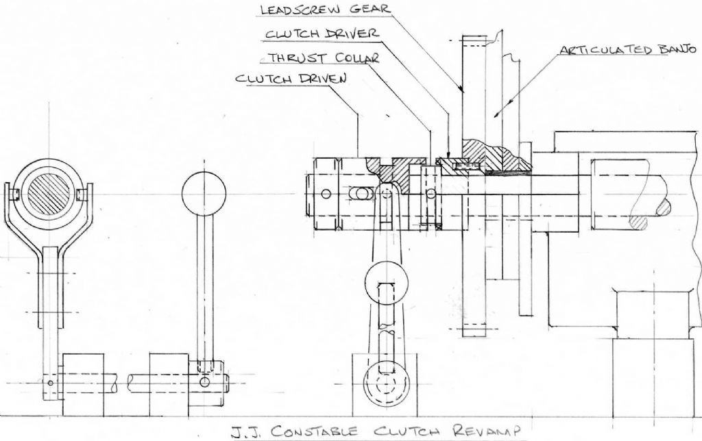
            You can breathe again! I enclose a sketch of a rehashed JJ Constable Leadscrew Clutch.

            Please remember that this is an idea only!

            jj constable clutch.jpg

            Halfway during the preparation of this sketch I redesigned an improved version in my head, thats what happens in the design function, so that this sketch is already out of date but I include it to show the principle.

            The sketch is workable but uses a lot of length of lead screw that isn`t there, so that an original lead screw will have to be extended. That`s not a problem for those that have split their lead screw already as a new length can be added.

            I`m now working on a version that will fit the EW without having to modify the original leadscrew.

            I`m also looking into a version of my modified Martin Cleeve clutch that will have an automatic disengage function.

            Alan

            #108430
            NJH
            Participant
              @njh

              Alan

              Look on this site at the thread " Screwcuting Simplified" ( and gasp in amazement! )

              regards

              Norman

              #108432
              alan smith 6
              Participant
                @alansmith6

                Norman and EWers,

                I have already bookmarked this very interesting thread that promises so much. I can`t say that i`ve studied it exhaustively but know that it involves the Myford lathe that is so very different to our little EW gem.

                Please remember that my self imposed brief is to churn out a design that will be compatible with the simplicity of the EW and be achieved with the minimum of work and also be an improvement to the function of the lathe.

                I`m not quite sure what I should be gasping about, so if you would be so kind as to save us the time of having to read through the thread by explaining what advantage to our EW the thread that you recommended will give.

                Alan

                #108439
                NJH
                Participant
                  @njh

                  Alan

                  I was responding to your post of 10.35 this morning where you were inquiring about Gray's screwcutting modification. Yes the thread shows the version for the Myford S7 but he has also designed similar for other lathes.( I doubt that he will do so for the EW.) My gasps of admiration refer to the design and the quality of Gray's work which I'm sure you will appreciate when you get time to study that thread.

                  Norman


                  Edited By NJH on 11/01/2013 16:20:23

                  #108452
                  alan smith 6
                  Participant
                    @alansmith6

                    Norman,

                    Sorry to be so obtuse, I misunderstood your reason for the post. The fact that "Gray" is Graham Meek escaped me. I promise that I will put some time into reading through the thread and thank you for bringing it to our attention.

                    Alan

                    Ps. When is the webmaster going to fix the problem that has occurred that the advertising is obscuring the text of the thread?

                    Edited By alan smith 6 on 11/01/2013 20:07:09

                    #108467
                    Sub Mandrel
                    Participant
                      @submandrel

                      Hi Alan,

                      Sorry to be slow responding, Norman has pointed you in the right direction already.

                      Neil

                      #108663
                      alan smith 6
                      Participant
                        @alansmith6

                        EWers and bookmarkers,

                        The last sketch that I posted was a rehashed JJ Constable type clutch that I had modified to hopefully improve the design. When I was halfway through the drawing, I realised that the design was only suitable for an elongated leadscrew and also contained parts that weren`t really required.

                        My next task was to shrink the clutch assembly lengthwise so that it would fit onto the end of the standard EW lead screw without modifying the lead screw.

                        The type of clutch is the same as in my version of Martin Cleeve`s lead screw clutch, namely a pair of half diameters that can only engage in one position.

                        What had to be done is shown on the sketch as " SHORTEST". The length of the driven clutch part is lost by incorporating it into the Myford gear which is 3/8" thick by boring out the gear and fixing the clutch into the bore by means of tiny countersunk screws. A circlip groove is machined into the lead screw in which is mounted a circlip whose function is to prevent the leadscrew gear / clutch assembly from wandering along the leadscrew into engagement with the other half of the clutch which could cause a nasty incident.

                        jj constable clutch variations.jpg

                        The clutch part which drives the lead screw is so drastically shortened that it has to be made in two parts; the first part is the annulus which surrounds the lead screw and has the slot cut in it for the retaining peg. The second part is the grooved portion in which the actuating gluts engage. This is a light interference fit on the annulus and is pushed into position after assembly of the annulus onto the lead screw.

                        The "COMFORTABLE" sketch shows a simple less difficult solution where the lead screw has been lengthened for some reason such, as the fitting of a large graduated handwheel on the leadscrew, which is another design I`m working on at the moment.

                        Please remember that these sketches are ideas only for the moment.

                        Alan

                        #109885
                        alan smith 6
                        Participant
                          @alansmith6

                          EWers and bookmarkers,

                          One of the limitations that I found with the EW when I got my first one decades ago, was the difficulty in having a graduated ring at the leadscrew handle. The problem is that the leadscrew position is very close to the top of the bed. To be precise, a nominal dimension of one inch from the top of the bed to the centreline of the leadscrew. The dimension from the CL of the leadscrew to the top of the rear leadscrew trunnion is nominally 7/16" so that the graduated ring could only be a max of 15/16"dia. Quite useless! Any more and the tailstock would not be able to be removed

                          I scratched my head looking for a simple solution to this problem and looked at making a removable handle that could be much bigger but remembered that I quite often used to have the tailstock pushed back over the end of the bed whilst doing a bit of milling.

                          I then made the sketch that I include below, which is a small gearbox to enable the leadscrew handwheel to be positioned remotely from the leadscrew itself.

                          ew leadscrew gearbox.jpg

                          What has happened that the leadscrew has an extension which lengthens the leadscrew by 7/8", the downside is that the leadscrew handwheel shaft has to be shortened to 5/8".

                          By doing this, the length of leadscrew that protudes from the back of the lathe is now enough to enable the fitting of the "comfortable" variation of the JJ Constable clutch as shown in my last post.

                          I had to make a hard decision in that I will have to drill two 2BA tapped holes in the back of the lathe. There is also a clamp that is positioned on the forward face of the gearbox and clamps onto the forward face of the rear leadscrew trunnion.

                          I won`t make a complete description of the gearbox but will add some dimensions to the sketch should the gearbox be successful.

                          The next sketch that I will be creating is the clutch operating details and the automatic feed stop.

                          Please remember that this is an idea only!

                          Alan

                          #109933
                          IanT
                          Participant
                            @iant

                            I agree about the utility of being able to take the tailstock on and off easily Alan. Mine gets removed with great freequency and this is likely to happen even more as things progress.

                            I have 'considered' this problem (but not got much further I'm afraid) and had decided that a larger dial and handle would be very useful (2"+) but that I would need to make it quickly removable – so some form of quick engage/disengage.

                            I also find that I'm using the boring table more and more and I'm getting tired of changing between this and the normal topslide. So one of my high priority jobs will be to make a simple mounting to fit my economy QCTH to the boring table – as I don't often seem to need to taper turn. Of course this will require the larger leadscrew dial to enable putting on the cut (using the topslide at the moment generally) and will also bring forward a saddle stop I suspect.

                            Still working on various things and one of them (boiler test pump) is progressing well. Photo is of EW Vertical slide mounted (via a simple adaptor plate) on the boring table. I'd just milled flats top and bottom on the ram yoke and I was about to cut the slot in the middle. Everything went well I'm pleased to report. The pump body is sat on the side of the boring table for reference.

                            EW & Vertical Slide

                            Hope this finds everyone well.

                            Regards,


                            IanT

                            Edited By IanT on 24/01/2013 23:15:57

                            #109937
                            Andyf
                            Participant
                              @andyf

                              Alan, if your leadscrew is fractional pitch like 8tpi, choosing the right gear ratio between the offset handle and the leadscrew would enable you to put 100 marks on the dial, each representing 1 thou, and one full turn of the dial reflecting 0.010" travel.

                              Compared with 125 graduations, this would eliminate some mental arithmetic if you want to shift the saddle along by (say) 0.460". With the right ratio, four full dial turns plus another 60 thou. That's easier than than 3 x 0.125 = 0.375", which when subtracted from the desired 0.460" leaves 0.085, so 3 full dial turns plus another 0.085".

                              Being a bit of a duffer at sums, I fitted a geared dial to my 12tpi leadscrew (a really awkward 0.8333" per turn) which has made life a lot easier, even though there's no idler and the dial contra-rotates.

                              Andy

                              #109961
                              IanT
                              Participant
                                @iant

                                I wonder whether such precision is really neccessary in practice Andy.

                                A simple leadscrew dial with a diameter of 2" would provide a dial circumference of 6.28" – so I could divide it by 12.5 and still have 0.5"+ between major divisions (each division being 10 thou). The addittion of a saddle stop, possibly with the option to fit an adjustable micrometer head would probably be more than enough for most of my turning needs on the EW. Generally I think I'd prefer to have some idea of where I am – but leave the "precision" to something mechanical (especially when boring for instance).

                                (Co-incidentally – a well-known online supplier sells a very nice little micrometer head for about £10 – I've just purchased one but not used it in anger yet).

                                Is it so awkward to have 12 major 10' divisions and a 5' last division?

                                It occurs to me to mention that for many years I tended to measure smaller distances in mm as I found fractional inch measurements much harder to manage (although a friend can add a long list of 'fractionals in his head – apparently converts it all to 64ths and then goes back). Personally, I used to always converted any smaller imperial measures into 'mm' for CAD drawings etc.

                                However, I have now returned to Imperial and prefer to work in 'thous' (which is a decimal system). It is just as easy use as 'mm' and most of my equipment is quite old and they mostly have imperial dials. My tooling is a mix of metric & imperial tooling – but I have a simple printed list (courtesy Excel) of common metric & fractional sizes > thous that I use and I've quickly become used to working in this way. All my new CAD drawings will now be in decimal Imperial (Inches/Thous). May sound like a step back – but it seems to work well for me. I'm not trying to reignite this age old argumemnt by the way – just stating how my preferences have evolved.

                                Regards, Ian T

                                #109974
                                alan smith 6
                                Participant
                                  @alansmith6

                                  Andy, IanT and bookmarkers,

                                  The diameter of the dial in my design is 3.25" and I was pondering about whether to gear up or just scribe the 125 lines on the dial as is but as this sketch is just an idea i`ve left this detail for later.

                                  As you can see the design lends itself to modification to suit individual preference but of course one of the limiting factors is the maximum size of the gear on the leadscrew which I chose from the HPC catalogue page 530.

                                  Talking about HPC, not in their 2012 paper catalogue but in their website there is a range of imperial leadscrews and nuts that are quite reasonally priced so that it is possible to replace your EW leadscrew should it be missing or damaged. You can even get them in LH thread if you wanted to change the rotation of the leadscrew and eliminate the necessity of the idler gear if using my proposed articulating banjo for the slow speed.

                                  I`m working on the clutch operation system which will incorporate an automatic clutch release which can be used as a stop for the saddle.

                                  Ian, I just love that EW vertical slide. If anybody has a spare one then I would be prepared to part with a large wad of notes to secure it

                                  Alan

                                  Edited By alan smith 6 on 25/01/2013 12:45:50

                                  Edited By alan smith 6 on 25/01/2013 12:51:12

                                  Edited By alan smith 6 on 25/01/2013 12:52:32

                                  #109975
                                  Andyf
                                  Participant
                                    @andyf

                                    I found it pretty essential when all I had for miling operations was a vertical slide, Ian. The dial on the topslide would cope perfectly well with most turning down or facing operations which require a degree of precision. But, as my lathe is a small one, its topslide is usually set at an angle so it doesn't foul the tailstock, and I have got into the habit of using the leadscrew dial.

                                    Andy

                                    #110127
                                    IanT
                                    Participant
                                      @iant

                                      I've always wondered how Mr Stringer meant his customers to mount the Vertical Slide quite honestly Andy.

                                      I am certain that the V/S is original EW equipment but with a single hole – I can only assume that it was meant to go on top of the cross slide – not the most stable mounting and mine won't quite fit (I think the toolpost pillar on mine is slightly bent).

                                      It makes much more sense to mount it on the boring table (also EW O/E) but it clearly won't mount as made. So a simple adaptor plate was made and seems to work very well. As you will see the tailstock has been removed simply for ease – it would be possible to work without it but I perfer to get it out of the way.

                                      I do quite like the idea of a geared leadscrew handle – but my work-rate it too low to add any more 'projects' to my list – life is too short (and getting shorter I'm afraid) and I would very much like to finish some of my other projects! The odd steam engine for instance!

                                      Regards,

                                      Ian T

                                      #110194
                                      MICHAEL WILLIAMS
                                      Participant
                                        @michaelwilliams41215

                                        I have a memory that ' Duplex ' described a comprehensive set up of screw cutting , fine feed , clutch and stops for a small Drummond in the late forties / early fifties . I haven't got a specific reference but there were certainly several separate series describing each attachment around that time .

                                        Michael Williams .

                                        Edited By MICHAEL WILLIAMS on 27/01/2013 11:43:05

                                        #110211
                                        alan smith 6
                                        Participant
                                          @alansmith6

                                          Michael & EWers,

                                          Thanks for the post, we have been looking at quite a few different solutions to our needs for the EW. Of course, it`s always interesting to see how others have tackled the same challenges that we are facing with it. Looking at other designs can suddenly ignite a spark that will turn into a better design than the one that one is working on.

                                          So far we have only considered designs that were created specifically for the EW and as it is so idiosynchratic, proposals that are put forward for more orthodox machinery can be difficult to adapt to the EW.

                                          I`m sure that all EWers will now be gagging to see these articles, it would be nice if somebody could find them.

                                          Alan

                                          #110213
                                          Andyf
                                          Participant
                                            @andyf

                                            Ian, I have a very similar vertical slide for my Perris lathe (still produced as the Cowells). Fixing is by a single stud into one of the Tee slots on the cross slide, a somewhat precarious arrangement.

                                            As to your dial, you mentiond that you could go up to 2" diameter. The one I made for my Iarger (but still small) lathe is about 2.05" diameter, and the 100 divisions are thus approximately 1/16" apart. Without stooping, they can be read easily using my varifocal specs. On a 2" dial, 125 marks would be about 1/20" apart, and should still be pretty readable. The fine downfeed on my Dore Westbury miller has 130 divisions on a 1.5" diameter dial, and those are getting a bit close together (and hard to see on the brass collar), though at least the dial is around neck height.

                                            Andy

                                            #110285
                                            IanT
                                            Participant
                                              @iant

                                              Michael,

                                              A quick ME Index check suggests that the Duplex articles you refer to might be part of their "In the Workshop" series. Volume 101 – Issues 2528, 2530 & 2532 may be the ones to look at I think. I'll see if I've got them this evening.

                                              Regards,

                                              Ian T

                                              #110286
                                              MICHAEL WILLIAMS
                                              Participant
                                                @michaelwilliams41215

                                                IanT ,

                                                I can identify one specific article :

                                                ' DUPLEX ' – In The Workshop series No. 89 .

                                                A Screwcutting Attachment for the Drummond 3 1/2 – in Lathe .

                                                ME Vol. 104 issue 2608 Thursday May 17 1951 – pp 643 et al .

                                                Very nice article . Refers back to previous articles but does not give dates . Anyway starting from this one article and working backwards should soon yield the others .

                                                Regards ,

                                                Michael Williams .

                                                #110391
                                                IanT
                                                Participant
                                                  @iant

                                                  I think i've found the relevant issue thanks Michael – No 2528 "In the Workshop" No 49 – A Saddle Traversing Gear & Fine Feed.

                                                  The design basically uses an intermediate set of gears that are disengaded by means of a 'bobbin' activated by a lever. As some modification to the quadrant is required, Duplex suggested that it would probably be best to use a dedicated quadrant for the unit and swop between this and the standard one as required.

                                                  Alan – if you would like to examine this design (for the ML7) I will scan it and send you a copy by PM.

                                                  Regards,

                                                  IanT

                                                  #110402
                                                  alan smith 6
                                                  Participant
                                                    @alansmith6

                                                    Thank you Ian,

                                                    I don`t like to leave stones unturned and whilst i`m sceptical that a design for the myford will be suitable for the EW I would be most grateful to see it.

                                                    Alan

                                                    #110404
                                                    MICHAEL WILLIAMS
                                                    Participant
                                                      @michaelwilliams41215

                                                      IanT ,

                                                      I don't know for sure but we could be at cross purposes . Picture in 2608 shows a neat set up on a Drummond lathe which doesn't seem like the one described for Myford in 2528 .

                                                      Regards ,

                                                      Michael Williams .

                                                    Viewing 25 posts - 201 through 225 (of 334 total)
                                                    • Please log in to reply to this topic. Registering is free and easy using the links on the menu at the top of this page.

                                                    Advert

                                                    Latest Replies

                                                    Home Forums General Questions Topics

                                                    Viewing 25 topics - 1 through 25 (of 25 total)
                                                    Viewing 25 topics - 1 through 25 (of 25 total)

                                                    View full reply list.

                                                    Advert

                                                    Newsletter Sign-up