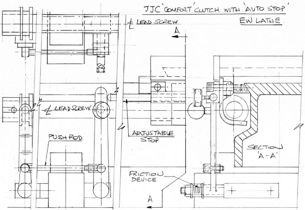
I enclose a scan of my latest idea for a dog clutch incorporating an adjustable stop for the slow feed.
I make no claims as to originality, what I have done is to throw all the ideas put forward, into the cerebral mixer and churn this out. Of course this idea can be adapted or improved by the reader as required.
What I have done is to leave the clutch lever in the original position as for the Martin Cleeve split leadscrew as shown in the first sketch. Extended the leadscrew at the headstock end by adding the extension piece as proposed in the leadscrew gearbox sketch and added the JJ constable "comfortable" clutch as in the JJC variations sketch.
So now we have a dog clutch that works without having to split the leadscrew, therefore eschewing a possible intermediate support for the split leadscrew.
The pushrod to actuate the clutch has to be placed low down in order to miss the slow feed gears. I recommend that the adjustable pushrod have ball joints at each end.
As for the adjustable stop, this is operated by a 1/4" dia rod adjustable axially, which pushes against the clutch operating lever therefore pushing the clutch out of engagement. This is mounted in a bracket that is fixed to the saddle by elongated leadscrew nut bracket screws. Remember to cut away the bracket so that there is access to the leadscrew nut adjusting screw.
The clutch operating lever requires a good base dia length to avoid deflection by the force of the clutch stop pushrod.
I should have done the sketch on two sheets and hope that those unused to engineering drawings will understand it. On the right hand side of the sketch is section AA, looking towards the headstock and to the left is a front view of the lathe in the area of the clutch lever. This view is shortened by splitting the view with the two vertical break lines. There is a small plan view in the top LHS of the sketch
The friction device is just a strong compression spring which will prevent the clutch lever from wandering out of the desired position.
This idea can be used either for the Martin cleeve variation or the JJC variation.
I will be investigating both situations by making prototypes when I have time.
It looks promising but I think somephotos would help me understand it a little better. So I look forward to seeing how you progress this project. Always easier to follow where someone has gone before!
Hopefully this is the type of saddle stop that you were asking about in an earlier post, or did you just want something static, or both? I will make a quick sketch to give an overview of the design for you.
Just out of interest, what would be the dimension between the front of the saddle and the headstock casting when you are working closest to the spindle?
Just got an idea that will satisfy both criteria ie. dynamic and static.
my son has just bought an EW and we collect it on Thursday. As far as I can ascertain, it has a motor, but no countershaft. I want to get the lad going on this as soon as possible, so does anyone know of any references to a simple countershaft design that is both elegant and reasonably easily made by two mechanically inclined guys, but not that well equipped with odds and ends?
We are not interested in power feeds, auto-cross feeds and certainly not remotely interested in electronics, so just a nice simple, reliable installation that can be moved around a bit in his small spare bedroom workshop. Something that goes with the period of the machine. I have a Peatol lathe and my son has a HUGE treadle/motor operated ancient in the carport, so we figured something in between indoors was a good idea. We are model makers rather than model engineers, but have always fancied making a working model engine as we're also petrolheads. He has a GT6 and I have an Austin 7 Special, for both of which it would be nice to make odds 'n' sods.
Michael, thanks for the links. I had seen the Lathes.co.uk site for the EW and that is the original style countershaft, but looking again, I think something very like the original could be fabricated, using ABC (Picador) loco type plummers, which I only discovered last night. Suitably finished in crackl black it would look just right, I think.
The micro lathe site is certainly a cornucopia of tinkering. Apart from locking levers on my Peatol instead of hex bits in a screwdriver, I can't think why people can't leave well alone with such a simple tool, but of course to some that in itself is the hobby. I also have a 1/4 horse motor which the Harborne man (Peatol supplier of Taigs) brought with him. It is contained within the footprint of the lathe base for compactness. All the belt tensioning thing is way over the top as I've only needed two belts in about 12 years! And my machine gets regular use as I am a professional modelmaker. OK, a quick change toolpost would be good, especially when making wheels for model cars, but I don't have a mill, so a little patience (which is the most I do posess) will have to go a bit further.
"We are model makers rather than model engineers, but have always fancied making a working model engine as we're also petrolheads. He has a GT6 and I have an Austin 7 Special, for both of which it would be nice to make odds 'n' sods."
Ah Martin – not model engineers eh? – it won't be long!
it's always lurked! And with the bigger lathe coming it may well not be long.
I once bit the bullet, bought all the castings for a Westbury Sealion from that funny little stationary shop in Oundle and started it on my old Unimat!! Then I got hard-up and flogged them all to the man in the Old Marmalade Factory in Oxford Now I can't afford them in the current form. Dammit.
But the Ron Collona 1/4 scale Offy has always appealed, especially in a 1/4 scale Miss Daytona boat.
Hallo Ruaidhri – long time since we heard from you but I hope this finds you well.
And yes Michael – that's Alan Smith's work – I recognised his EW clutch immediately and he's made a super job of his slow speed banjo too. Nice to hear from them both after all this time.
I've just checked… Ruaidhri – your first post on this EW thread was in December 2010
Congrats on your article Ian T, just a little post to to tell you all that I`m back but no fireworks this time! I`ve been grafting away with workshop but having to move twice in two years has set me back a little. There are plans to make new castings for the original style EW countershaft but it`s difficult to find a foundry here in Oslo!
I now have a complete EW lathe with all the accessories except for the vertical slide.
I recently converted a large galvanised bottled gas storage cupboard into a proper home for my other EW lathe plus plenty of storage.
I`ve just prepped an original EW countershaft ladder frame to serve as a pattern for an aluminium casting. This is an experiment to see if aluminium is man enough for the job as the originals were cast in cast iron. If this is successful then if anybody is interested in having a copy to fit to their EW, then let me know.
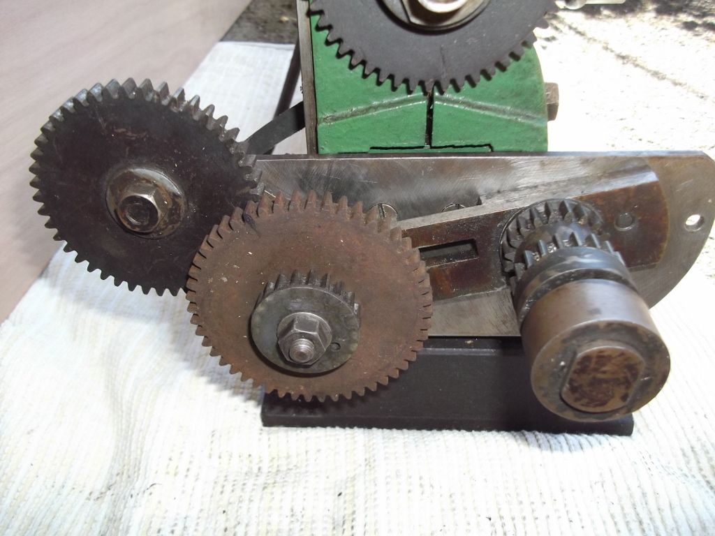
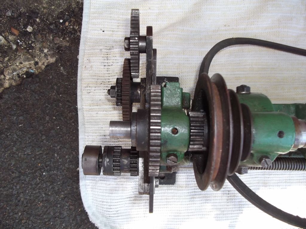
Phil Kessel contacted me via my website, asking my help to sort out the screwcutting set up on his EW lathe. I looked through his photos and suddenly realised that this was a JJ Constable slow feed with clutch. I don`t think that I`ve ever seen any of the proposed modifications to the EW in the flesh so that this is quite an exciting find.
I`ve added the J J Constable slow feed article to my Photo Album if anybody wishes to refer to it. I`ll add some photos once I`ve uploaded them.
I have purchased my first lathe. A VGC EW Stringer Ver.D Lathe. The only part of the set up i would like to change is the original motor. My question: What new motor best suits this small lathe.
Has anyone made modifications to this small lathe?
I am going to read some of the articles posted in this thread as well. I am totally new to lathes