Stress Fracture

Advert

Stress Fracture

Home Forums General Questions Stress Fracture

Viewing 21 posts - 1 through 21 (of 21 total)
  • Author
    Posts
  • #196784
    Nick_G
    Participant
      @nick_g

      .

      Hi guys. smiley

      Had a bit of a 'situation' with a part of my lathe causing me some disharmony.!

      A bit complicated to explain, so I made a video for your thoughts and opinions. Here :- **LINK**

      I made this video and this thread for no other reason than to perhaps create an interesting topic to others as my harmony is now again restored and I have ceased from my initial 'rude words'. angel


      Nick

      Edited By Nick_G on 14/07/2015 23:42:29

      Advert
      #23983
      Nick_G
      Participant
        @nick_g
        #196788
        David Colwill
        Participant
          @davidcolwill19261

          I think that any of your ideas about the fracture could be right. I don't think you will ever know for sure.

          I think it would be more useful to use your old plate to fix a second toolpost to hold a parting tool upside down as far back as practical. I have this arrangement on my Smart and Brown and it is very convenient.

          As to the old toolpost how far does the cam turn round? If it isn't turning far enough, removing some metal off the cam may help it. I would try putting it in the lathe and applying a powerfile or even just emery paper (covered of course) and see if that improves it.

          Regards.

          David.

          #196789
          Cabeng
          Participant
            @cabeng

            You might have answered this in your clip, but if so, I missed it!

            What material is the plate made of?

            You have a PM re your AXA toolpost.

            #196790
            Gary Wooding
            Participant
              @garywooding25363

              Hi Nick,

              My first lathe was a Boxford CUD, which had a Boxford VS (vertical slide) that was attached to the cross slide the same way as the tool post in your video.

              On one occasion I got over confident when milling and the VS was wrenched right off of the cross slide. I didn't notice any fracture in the plate afterwards, but I was a total newbe and didn't think to look. Could your lathe have suffered the same or similar trauma before you got it?

              I drilled another couple of holes for additional holding pins, plus was a lot more careful, and never had the same mishap again.

              #196792
              JasonB
              Moderator
                @jasonb

                Obviously done by the latest ham fisted ownersmile p

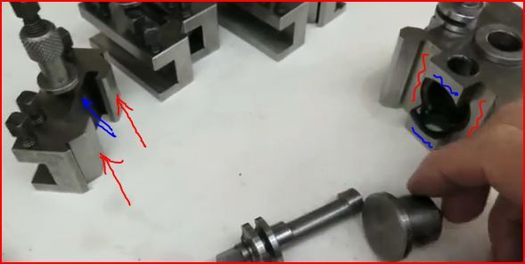
                Regarding the old tool post I found on some of the imported toolholders that they bottomed out on the post before the cam was fully tightened where I have marked in red. Quick touch to the two arrowed areas on a linisher soon had them holding tight. You may also want to look at the areas marked blue for a similar issue.

                If you could sort that then the toolpost could be mounted on a raising block ontop of your repaired plate at teh rear of the cross slide.

                nicks post.jpg

                #196795
                Muzzer
                Participant
                  @muzzer

                  Looks like cast iron. The section above the thread looks pretty thin and must be in considerable tension when the screw is heaved tight, so a hairline crack is probably how you'd expect to see it begin to fail. It does seem rather thin there.

                  Instead of trying to weld or braze a repair which would be tricky in CI, perhaps you could bolt (multiple fasteners) a steel strip along the front with a new, deeper threaded bolt hole. You'd still be compressing the pin but with a reduced level of tension (stress) in the main body around the crack. Adding more bolts as you suggest must be a sensible route too.

                  Nice to see your new AXA toolholder. Let us know how you get on with it!

                  Murray

                  #196800
                  Michael Gilligan
                  Participant
                    @michaelgilligan61133

                    Nick,

                    That's a very useful video … a picture's worth a thousand words, and that is certainly worth several thousand.

                    Like Muzzer; I presume the plate material to be cast iron [and it looks to be of the appropriate quality, too] … Excellent stuff in compression, but poor in tension etc.

                    I think the most likely explanation is that the initial damage was caused either by running the top-slde into the tailstock, or [more likely] by some 'impact' event … This would initiate a crack at that weak point, although it may only have been microscopic. … The crack then gets extended by a process known as 'Stress Corrosion' [and your rattly toolpost is almost certainly the source of input energy for that].

                    Excellent news that Boxford still had a spare plate available !!

                    I wouldn't bother trying to repair the cracked plate … just use it in some configuration where it is only seeing compressive loads.

                    MichaelG.

                    #196801
                    Capstan Speaking
                    Participant
                      @capstanspeaking95294

                      All of the torsion from the cutting forces is passed through to the two pins. The leverage must be enormous. If they are used for clamping the compound slide too then that will add to it. I'll bet it suffers from poor rigidity too.

                      I think the replacement plate will fail under heavy load. There is scope to improve the mechanism though.

                      #196804
                      KWIL
                      Participant
                        @kwil

                        Over enthusiastic tightening of the "pad" screw in the front of the plate (possibly with the aid of a hammer) would not have held the tapered spigot of the topslide with a much improved tension, it would however have easily pulled the mounting plate at that point outwards towards the front.

                        This I would suggest is the primary cause of the radial spllt in the plate to be exacerbated by the rotational forces of the cutting tool.

                        The QCTP post type previously used are fine if as Jason has pointed out, the parts are correctly made and tightened. The cam action of the cheaper copies is not always correctly set up due to sizing problems. ORIGINAL Dickson TPs did not suffer in that respect.

                        #196810
                        Neil Wyatt
                        Moderator
                          @neilwyatt

                          As capstan says, the toolpost is essentially levering on the screw.

                          Neil

                          #196812
                          colin hawes
                          Participant
                            @colinhawes85982

                            Vee screws produce a bursting effect on a threaded hole as they have a wedging effect against it so overtightening could cause this type of fracture which is one reason for vices to have a square or buttress thread. Colin

                            #196820
                            David Colwill
                            Participant
                              @davidcolwill19261
                              Posted by colin hawes on 15/07/2015 12:24:41:

                              Vee screws produce a bursting effect on a threaded hole as they have a wedging effect against it so overtightening could cause this type of fracture which is one reason for vices to have a square or buttress thread. Colin

                              Good point. I hadn't thought of that. It's certainly something to bear in mind.

                              Regards.

                              David.

                              #196829
                              Ajohnw
                              Participant
                                @ajohnw51620

                                Boxford have used that clamping arrangement on all of their lathes that I am aware of even my ME10 but both screws go in from the back. The cross slide bulges out where the compound sits. The metal thickness at above the holes looks similar. I've never heard of one cracking.

                                I would wonder if the crack was their when you bought the lathe. Putting the screw at the front like that seems to be a rather retrograde step as cutting forces will be acting directly on them. Maybe the plate can be swung round to prevent that.

                                The other reason it may crack could be down to well over tightening them. Don't know what is supplied with your lathe but mine has the hex key for them is on one end of the chuck key handle. They only need firmly nipping up as considerable force can be applied via the screw – put the 2 together, plate orientation the wrong way round and the compound slips – more tightening etc.. Crack.

                                Maybe the marks on the tailstock are down to metric screw cutting if it's an imperial lathe. I assume that on the metric version they supply the same type of screw cutting indicator as they do on the usual older Boxfords. It allows many of the pitches to be cut in the normal way by disengaging screw cutting at the end of the cut and winding back by hand. The choice of 1 of 2 gears on the indicator maintain sync with the thread.

                                I assume that the power feed is still the same so that wouldn't mark the tailstock badly. It's effectively a friction drive so that it can be run up against a bed stop. On the older lathes the drive is obtained via a slot that runs down the lead screw that drives a keyed bush. The friction level can be adjusted with a knob on my ME10.

                                I wouldn't think of welding to try and repair it. Cast iron isn't well know for welding well. I'd simply clamp firmly and add some straps to the outside. 6mm thick ms should be fine screwed and doweled or roll pinned to the edge. There is a sort of stapling method but it would need more space than you have. I've seen it used to fix large miller head castings – some one walked away and left the vertical power feed on.

                                wink If you want to throw your dodgy QCTP away please use my dustbin. I'd say the problem is too much cam action and maybe incorrect material. Over time I suspect you wouldn't be able to get the screws out of the holders as the ends will bell out. Best fit high tensile screws.

                                John

                                #196851
                                Ajohnw
                                Participant
                                  @ajohnw51620

                                  Unless my spatial awareness is having a bad day if you reverse the plate the tightening points will be in a more sensible place – one at the back and one at the side nearest the head stock. BUT looking at one one of Boxford's images of a 330 they have one at the front. The casting on these is very different but that might be to just raise the centre height of the tool post.

                                  Interesting area. They could of easily put the screws on the front of the bulge in the cross slide on the older lathes but didn't. These lathes are generally a direct copy of a USA South Bend I'd guess that they will be in the same place on those. They look like both pins come in at near 90 degrees apart at the back equispaced around the centre line.

                                  John

                                  #196859
                                  Nick_G
                                  Participant
                                    @nick_g
                                    Posted by JasonB on 15/07/2015 07:51:03:

                                    Obviously done by the latest ham fisted ownersmile p

                                    .

                                    Meeeeeeeeeeee. 'Ham fisted' …………………… Never.! indecisionsurprise

                                    Although I do remember years ago having a 'play' in a D8 Cat bulldozer. ……. It was great.! laugh ……. That is unless you were a van, a wall or a tree that is.! blush

                                    You guys may have raised a valid point on the over tightening front. This is I feel now possibly the cause of the fracture and the tool post was another issue all together. (although it will not have helped) The method I used was to tighten those grub screws as tight as I could. Then an extra tug just to make sure. Thinking about it once explained it was not the best thing to have been doing.

                                    Running back into the tailstock by a previous owner. I think I would probably have noticed the crack before now.

                                    I spoke to the spares guy at Boxford again today. Who in a previous conversation had told me he had been with them for 42 years. And had probably had a hand in making the machine I now own. I asked him if this plate cracking was a known issue and common. He informed me that he had been in the spares department for over 10 years and this was the first plate that he could recall selling. But he could not speak for others.

                                    For anyone that wants a view of the general construction. Here is a pic.

                                    Cheers all, Nick

                                    #196866
                                    Andrew Johnston
                                    Participant
                                      @andrewjohnston13878

                                      So, is the plate steel or cast iron?

                                      Andrew

                                      #196868
                                      Brian Wood
                                      Participant
                                        @brianwood45127

                                        Hello Nick,

                                        The failure has all the hallmarks of a fracture in cast iron, it will be present on the underside of the plate too. Good as you say your welding friend is, he will not be able to repair that satisfactorily for you, it is too thin. Others have suggested fitting a 'strongback' to clamp the crack closed.

                                        I fear that too is a futile solution as the wedging action in clamping the compound slide is very strong and it will still cause the crack to gape and eventually that action will distort the screws holding the strongback in place, leading to complete fracture on the side opposite the present crack.

                                        Now that you have a dependable spare I would be very tempted to make a faithful copy of the plate in decent steel and then use that for normal working. Your intact plate could then be moved as you suggest to the rear of the X slide for use when parting off.

                                        I am sorry to be so gloomy about the prospects for salvage, but I suspect the previous over run into the tailstock started the problem, to then be compounded by the trouble you have had in parting off with slop developing in the tool holding block. I think Jason has shown very well how that might be rectified and brought back from the scrap bin.

                                        Regards

                                        Brian

                                        Edit  I rather suspect that all that has been holding it together across the crack are the mounting screws holding it down on the cross slide

                                        Edited By Brian Wood on 15/07/2015 20:22:29

                                        #196870
                                        Ajohnw
                                        Participant
                                          @ajohnw51620

                                          I'd say the plate is probably made from continuous cast iron these days as it would be cheaper than what is usually done with lathe castings to de stress them.

                                          Afraid if I made a copy of this layout I would revert to the old style clamping – 45 degrees either side of the centre line at the back. They could have easily put them more conveniently for users on the front of the older Boxfords and didn't.. The casting would take them in either position. I wonder why? Not really. I'd probably use steel but it bruises more easily than cast iron.

                                          John

                                          #196878
                                          Phil Whitley
                                          Participant
                                            @philwhitley94135

                                            I was going to say "make a steel one" but Woody beat me to it. That casting is very thin, and seriously weakened by the holes for the clamps. You can't easily thicken it up without raising the centre height of the toolholder, so the thing to do is to use a stronger material.Given that lots of Boxfords went to schools, I feel they may have sold more of these parts than they are telling . Any slackness in the holding down bolts would also put it under extreme strain, especially in a dig in situation. Parting off on a lathe is the purest test of how rigid the machine is (I HATE it)

                                            Phil

                                            #196891
                                            Ady1
                                            Participant
                                              @ady1

                                              I was going to say "make a steel one" but Woody beat me to it. That casting is very thin, and seriously weakened by the holes for the clamps.

                                              Got a bit of steel you can use. Took 30 hours to chop it off at 10 quid an hour

                                              …postage is free!

                                              Edited By Ady1 on 16/07/2015 01:48:46

                                            Viewing 21 posts - 1 through 21 (of 21 total)
                                            • Please log in to reply to this topic. Registering is free and easy using the links on the menu at the top of this page.

                                            Advert

                                            Latest Replies

                                            Home Forums General Questions Topics

                                            Viewing 25 topics - 1 through 25 (of 25 total)
                                            Viewing 25 topics - 1 through 25 (of 25 total)

                                            View full reply list.

                                            Advert