Strength of Cast iron

Advert

Strength of Cast iron

Home Forums Materials Strength of Cast iron

Viewing 25 posts - 1 through 25 (of 60 total)
  • Author
    Posts
  • #29814
    Peter G. Shaw
    Participant
      @peterg-shaw75338
      Advert
      #353546
      Peter G. Shaw
      Participant
        @peterg-shaw75338

        Hi folks,

        I am looking for informed opinion on the strength of cast iron when subjected to an extracting force of about 16kg via either a M6 or a M8 bolt.

        In MEW 251, Phil Dawes describes how he modified his SX2P milling machine by replacing the spring loaded side lifting arm by a counterweight system. As I have a Warco MiniMill (X2 clone) using the same system, I thought that it should be possible for me to do the same.

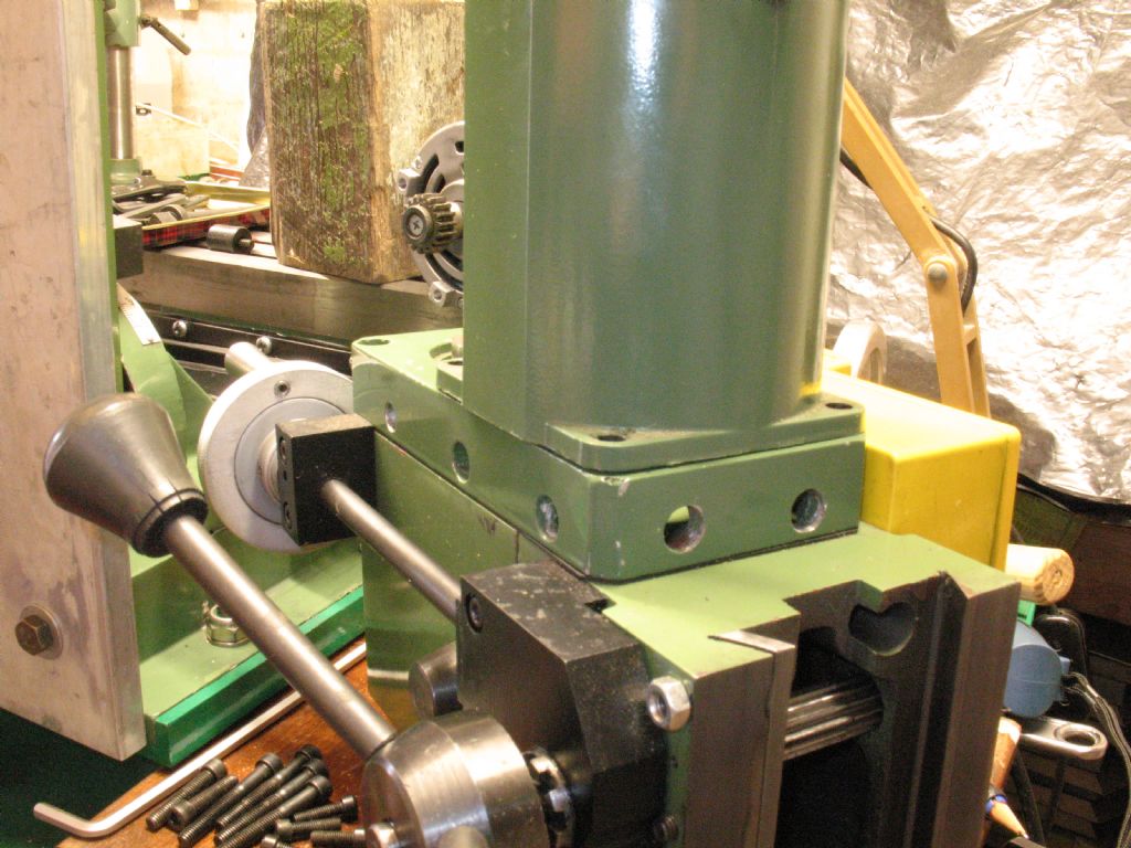
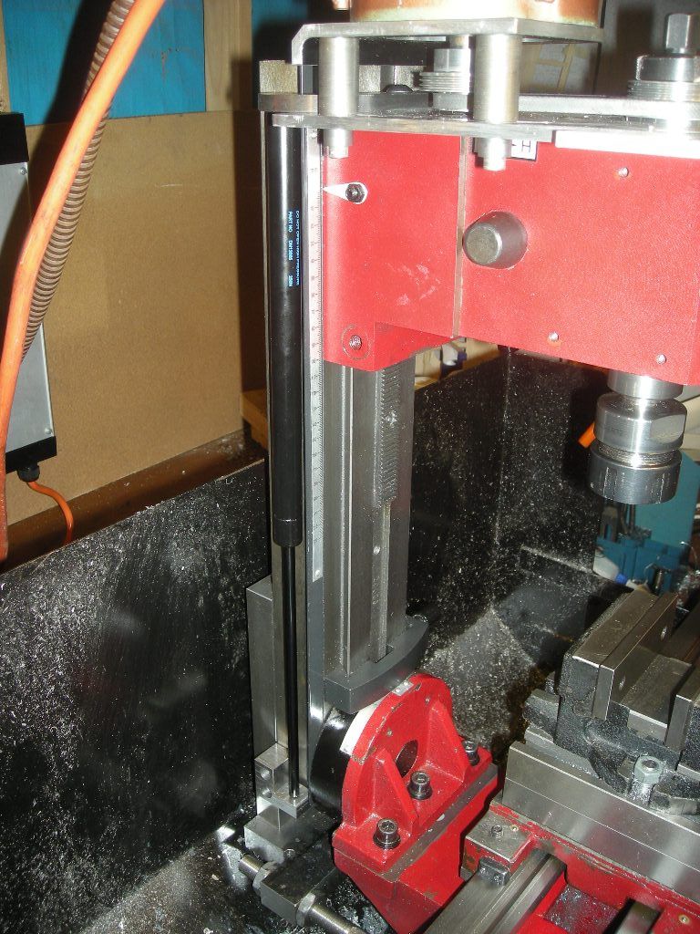
        Phil says that he was able to attach the lifting chain to the milling head by means of the two rear bolts holding the motor to the head. As the photo below shows, I do not have those screws, and the two nearest screws do not have sufficient room to have a suitable bracket attached.

        img_5349.jpg

        It seems to me that my alternatives are to either replace the cast aluminium spacer between the motor and the actual milling head with a longer spacer but this then poses problems with creating the spacer on the lathe, the lengthened spacer being 200mm long, or to fasten the lifting chain directly into the dovetail section of the milling head.

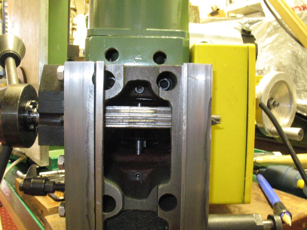
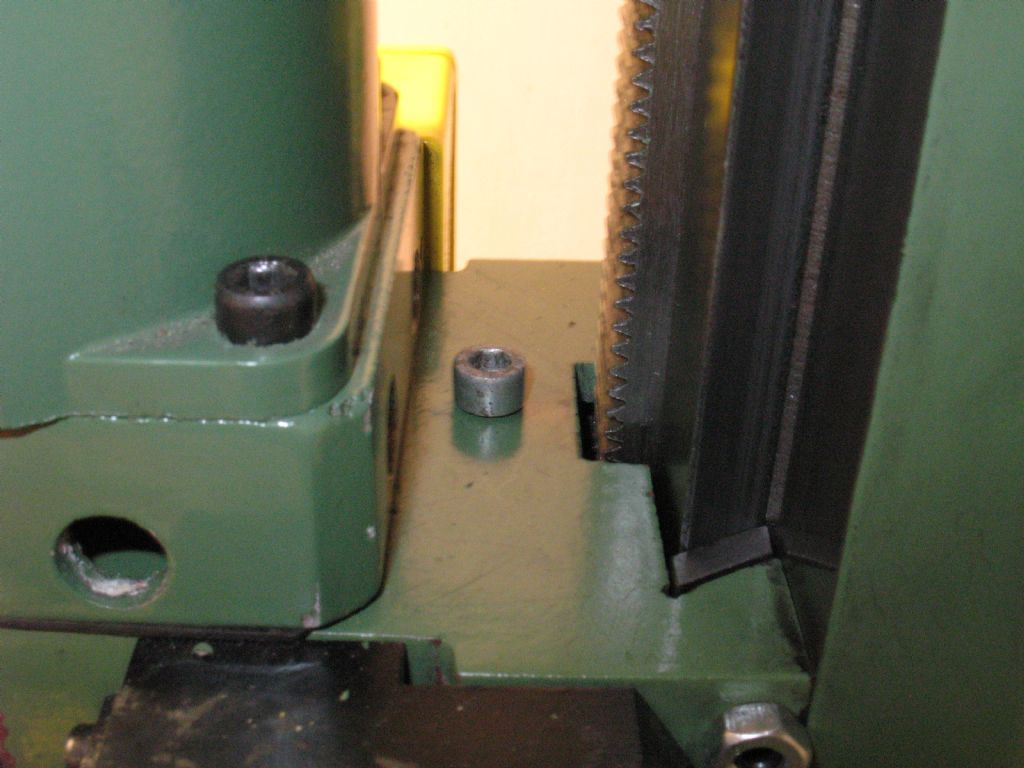
        The flat surface of the dovetail is about 23mm wide where the rectangular cutout is whilst the vertical thickness is 11mm.

        The second photo shows a close-up of the rear of the dovetail.

        img_5351.jpg

        You will be able to see that there are caphead screws down the two holes, whilst in the middle of the cutout section can be seen a dowel which serves to ensure that the two halves of the head are correctly located.

        As I see it, I can either use a single M6 thread or a single M8 thread into the top of the dovetail, hence the thread would be 11mm long. I suspect that M8 would be better as then the individual threads would be thicker, and therefore stronger. Alternatively, I could shape a piece of 6 to 8mm thick steel to fit inside the curved section with a clear hole through the cast iron. This would have the effect of compressing the cast iron and at the same time spreading the lifting load over a larger area.

        Ideas & thoughts please. Incidently, I am proposing only using one screw through the cast iron. I feel that providing two screws, even if only M6 might weaken it too much.

        MTIA

        Peter G. Shaw

        #353551
        David Murray 1
        Participant
          @davidmurray1

          Unbrako have a good PDF on the subject **LINK**

          #353557
          Neil Wyatt
          Moderator
            @neilwyatt

            I would expect even a small fixing like an 8BA screw to take 16kg in CI, if there are no shock loads.

            An online calculator suggest that with 11mm thread depth in cast iron, the pull out strength for M6 will be about a ton, so you should be OK.

            http://www.tribology-abc.com/calculators/e3_6f.htm

            I used a yield strngth of 130 MPa isntead of shear strength.

            Neil

            #353563
            vintagengineer
            Participant
              @vintagengineer

              I was always taught the maximum strength of a thread was 1 1/2 x diameter.

              #353564
              John Reese
              Participant
                @johnreese12848
                Posted by vintagengineer on 11/05/2018 13:50:41:

                I was always taught the maximum strength of a thread was 1 1/2 x diameter.

                It depends on the shear strength of the bolt and of the tapped material. You need more engagement in a soft aluminum part than in hardened steel. It also depends on the class of the threaded hole, but to a lesser extent.

                #353612
                Neil Wyatt
                Moderator
                  @neilwyatt

                  Also depends on how elastic the material is. Often the load is taken on only a few threads, but you don't need many for the thread to be stronger than the core of the screw.

                  Neil

                  #353616
                  Tim Stevens
                  Participant
                    @timstevens64731

                    If you mean the maximum strength that a thread can give in tension is achieved when there is 1.5 diameters of engagement, you may well be right. But I just wonder who else had to sit and think for a moment how the strength (tons per square inch, newtons per m squared) could possibly equal the diameter of anything.

                    In my experience, the guidance that three turns of thread do all the work is another way of looking at the same relationship. And somewhat easier to understand, perhaps.

                    Cheers, Tim

                    #353618
                    Tim Stevens
                    Participant
                      @timstevens64731

                      Peter – to try to offer an answer: There are two fairly big holes in the back face of the motor support block. It seems possible to add a plate bolted to these holes – simple bolts, nuts, washers – and then add your chain, hook, etc to the plate. This would mean that the strength of the attachment depended on –

                      a) the two bolts in shear – and they look like 10mm each, ie plenty;

                      b) the thickness and material of the plate – up to you and your scrap stock.

                      And in the event of failure of the extra support, no damage would be caused to the machine.

                      Regards, Tim

                      Edited By Tim Stevens on 11/05/2018 21:03:49

                      #353619
                      richardandtracy
                      Participant
                        @richardandtracy

                        If it is really cast iron, as opposed to cast steel, then the strength will be very much less than expected.

                        At the turn of the 1800's to 1900's, the max tensile strength for cast iron was considered to be 2000 psi, and anything stronger was cast steel. In modern units, this is 13.8 N/mm^2. So, the shear strength is 65% of that at 9 N/mm^2. This goes a long way to explain why Victorian machinery was so huge for its output.

                        Regards

                        Richard.

                        #353626
                        SillyOldDuffer
                        Moderator
                          @sillyoldduffer

                          Cast Iron is notoriously weak in tension as shown by the Tay Bridge and other disasters. Also worth knowing that cast iron has low fatigue strength in addition to low tensile strength. It's not safe to stress cast iron repetitively without bumping up the safety factor considerably.

                          #353633
                          mahgnia
                          Participant
                            @mahgnia

                            Peter,
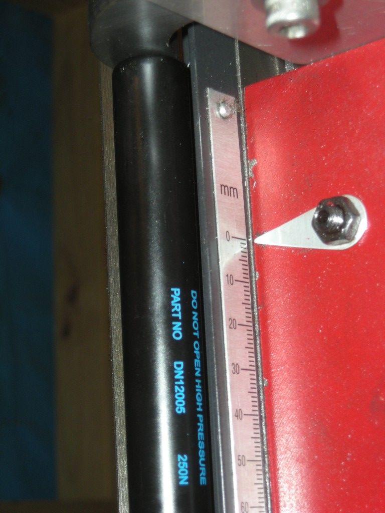
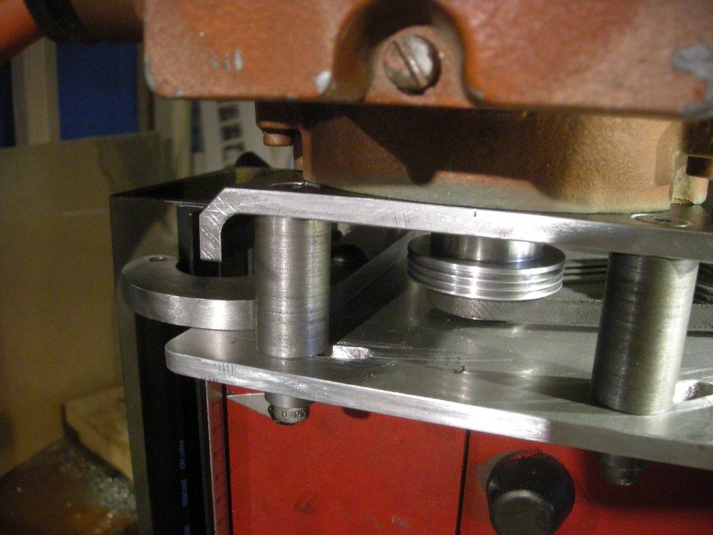
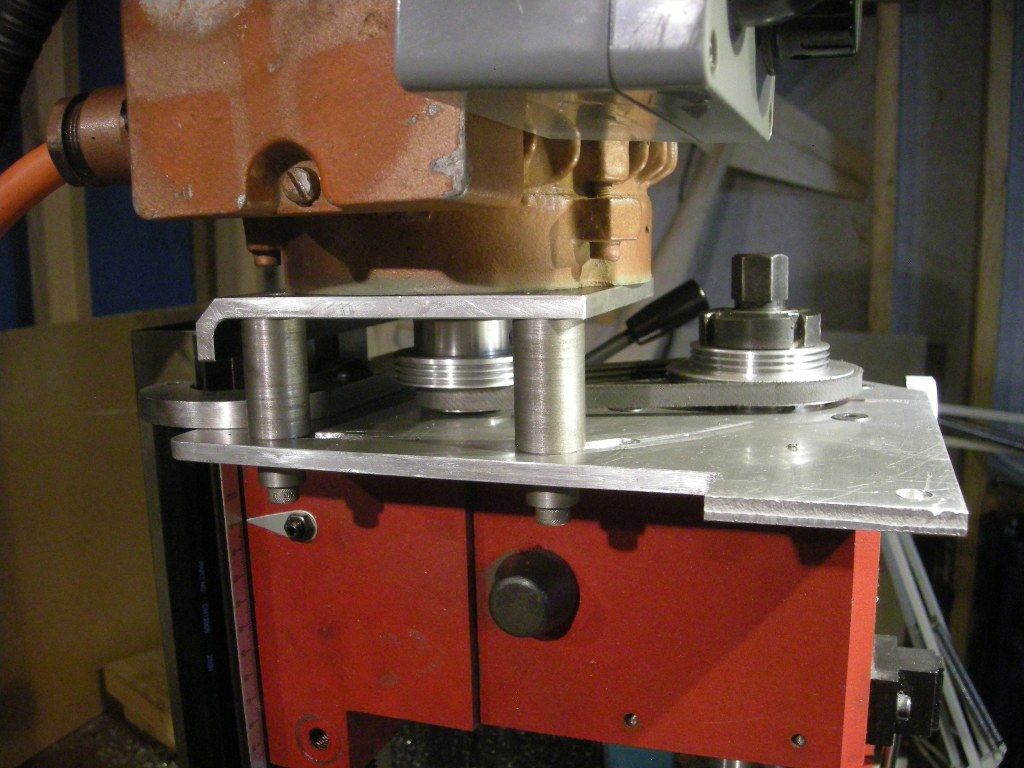
                            My X2 has been modified to use an air spring to support the head with the additional weight of a 3 phase motor. Two M8 cap screws into the cast iron rear housing/dovetail area have been sufficient for several years without any issues.

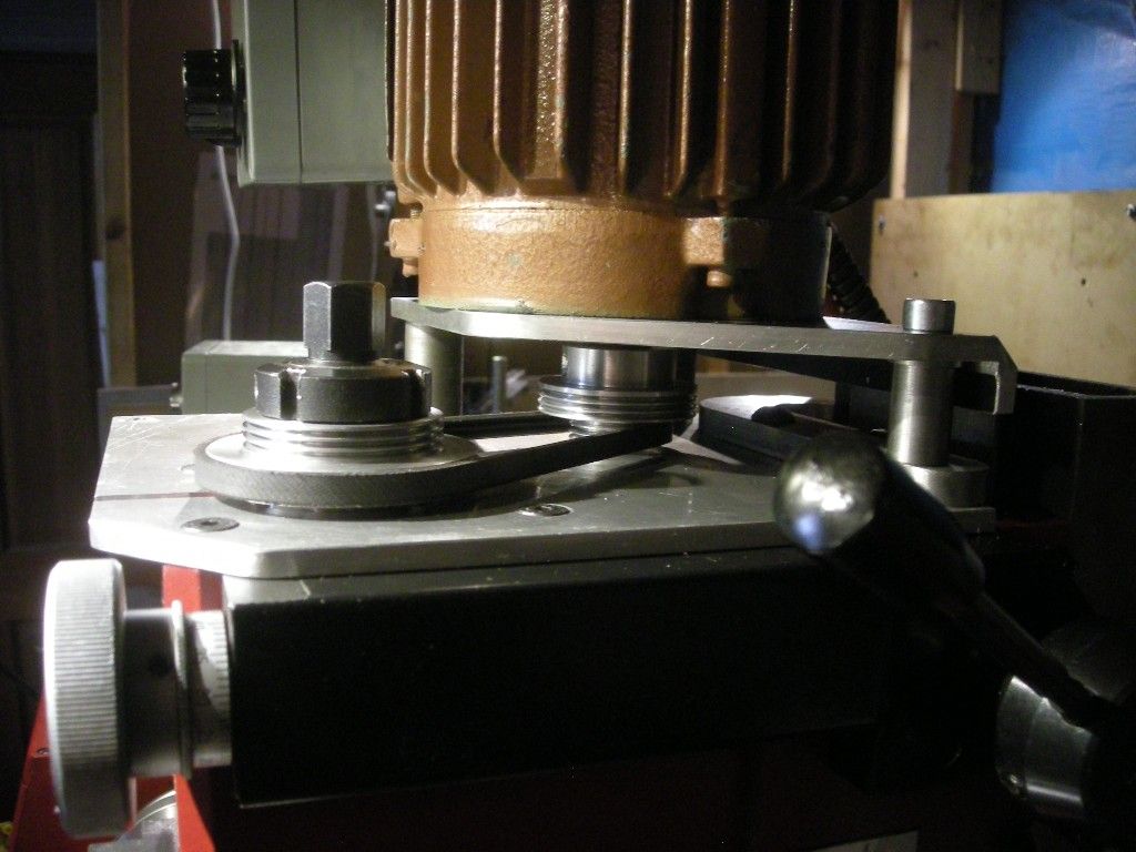
                            The photos below show the setup as it was before further mods recently, including moving the mill head from the lathe and attaching it to an SX1P X-Y table.

                            Andrew.

                            dscn8608.jpgdscn8983.jpgdscn8993.jpgdscn8992.jpgdscn8991.jpgdscn8984.jpgdscn8979.jpg


                            Edited By mahgnia on 12/05/2018 06:48:30


                            Edited By mahgnia on 12/05/2018 06:53:56

                            Edited By mahgnia on 12/05/2018 07:04:26

                            #353659
                            Anonymous

                              If the material is proper cast iron pull out of threads shouldn't be a problem. Generally the thread form in shear will be stronger than the tensile strength of the core of the screw.

                              Some years ago I needed to fit some high tensile M4 (Grade 12.9) screws into an aluminium (6082) heatsink where clamping forces of several hundred Newtons were needed. I did some experiments drilling and tapping holes in an aluminium block using thread engagements of 70%, 60% and 50%. I started with the 50% hole, and the screw broke before the internal thread stripped.

                              I also broke a number of SHCS when replacing the feed gearbox cover on my horizontal mill. The sequence went, nearly tight, tight, just a little tweak for good measure, ping! The screws were steel and the gearbox cast iron.

                              Andrew

                              #353664
                              Samsaranda
                              Participant
                                @samsaranda

                                Remember in the 60’s, in my youth and well into motorcycles, I was refitting the cylinder head on my Matchless G80 and was tightening the cylinder head bolts, high tensile steel bolts, cast iron cylinder, and in those days I was usually over enthusiastic when tightening bolts, before I had a torque wrench, well one of the bolts let go with a mighty crack and the spanner flew out of my hand with the top half of the bolt. No damage to the cast iron threads of the cylinder which is a testament to how strong threads are in cast iron. I can’t remember having ever stripped or pulled out threads in cast iron.

                                Dave W

                                #353679
                                Ian S C
                                Participant
                                  @iansc

                                  While still at school one of my nephews took up old beat up motor bikes as a hobby, so I bought him a set of spanners, and made sure I got the shortest ones I could, I don't think he broke any bolts, his half brother was into old cars(Morris Oxford etc), and he broke a few studs, but I got him sorted in how to get the broken bit out of the engine block. The first lad is a cabinet maker, the second is a diesel mechanic with his own business(and uses a torque wrench).

                                  Ian S C

                                  #353680
                                  Samsaranda
                                  Participant
                                    @samsaranda

                                    Big yes for torque wrenches or some method of limiting torque, I.e. shorter spanners. We learn from our experiences.

                                    Dave W

                                    #353683
                                    I.M. OUTAHERE
                                    Participant
                                      @i-m-outahere

                                      I mounted an air spring onto my X2 with a simple post bolted to the rear top surface of the head using 5mm cap screws and it is rock solid , the air spring is way too strong for what i need and has enough power to drive the head back up to the top of the column if i let go of the handle ! Peter if you want a photo of it let me know .

                                      #353765
                                      Peter G. Shaw
                                      Participant
                                        @peterg-shaw75338

                                        Hi all,

                                        Thanks for all the replies. Some answers.

                                        Tim. The spacer appears to be a cast aluminium block, well not so much a block as 4 sides and a top about 6mm thick with a few ribs therein. It's lightweight, so I don't think it's either steel or cast iron. I have to admit that when it comes to cast aluminium or cast iron, I'm rather shy about putting any load on.

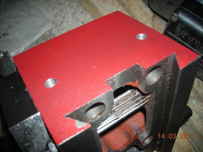
                                        Richard. I have now drilled and tapped the casting (see photo – caphead screw inserted). I used the workshop cleaner to suck up any dust as it was produced so didn't see the dust. I drilled & tapped easily without using any tapping liquid or grease. I'm reasonably certain it is cast iron.

                                        Andrew. I understand what you are suggesting but I would then need to modify the spacer to be able to use them.

                                        XD351. That's just the sort of answer I was looking for. No photo required, thanks.

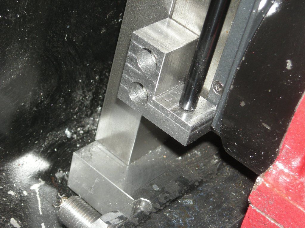
                                        To all. I've now drilled and tapped for M6 as shown in the photo, eg the cap head bolt near the rack.

                                        img_5353.jpg

                                        You will notice that I haven't got much space to play about with, and indeed having done it, I now find that the top part of the motor cover means that the lifting chain will have to be attached on the rack side of the screw. In addition, there is a mechanical stop at the top of the column which may get in the way, but that can be made shorter or even permanently removed if necessary.

                                        Finally, I'm not an engineer by training. Everything I know has been learned either by reading and experimenting or just by experimenting. As in Tim's reply, I am somewhat leery when it comes to castings as my very limited experience suggests that they can be brittle and thus easily break, especially if subjected to a stretching or bending force hence my question.

                                        Anyway, thanks again.

                                        Peter G. Shaw

                                        #353767
                                        HOWARDT
                                        Participant
                                          @howardt

                                          I made a pulley system with a couple of gas struts for my SX2P. Photos are in one of my albums. I used a wire rope and fixed this into a block which is fitted to the cable after it is passed through a plane hole in the top of the spindle bracket. It works very well and balances the head perfectly. The hole strut assembly drops into the column and held with some screws in the top face.

                                          #353768
                                          HOWARDT
                                          Participant
                                            @howardt

                                            I also took the opportunity to pack the rack out on the column. This improved the movement of the head, whilst it didn't remove all the play from the pinion it was a lot better than as built.

                                            #353788
                                            duncan webster 1
                                            Participant
                                              @duncanwebster1

                                              you'd be better off attaching the chain in line with the M6 screw, can you screw an eye bolt in?

                                              #353791
                                              Neil Lickfold
                                              Participant
                                                @neillickfold44316

                                                I only buy and use the 12.9 capscrews. Where you have the M6 screw, to secure a a lifting point, you could thread a piece of steel bar, wind it in to it is finger tight, then mark where you can drill a cross hole, and use a 6mm shackel to attach a chain or what ever else you want. The connection can also be made with a long grub screw, with enough sticking out to screw on the adaptor for a lifting something. You have room for at least a piece of 12mm something. You could also modify a capscrew , put a 6mm thread on one end, skim down the socket head(if it is too big) then drill the crosshole for a shackel also. Neil

                                                #353802
                                                Neil Wyatt
                                                Moderator
                                                  @neilwyatt

                                                  Just a thought, the expected load on the M6 screw is 16kg.

                                                  My test of an M6 screw in a 3D printed PLA cube saw a gradual failure begin at 240kg (approximately as the load was applied using a 10:1 lever).

                                                  Neil

                                                  #353861
                                                  Peter G. Shaw
                                                  Participant
                                                    @peterg-shaw75338

                                                    Neil W.

                                                    I've now actually measured the weight of the head and all its gubbins using the bathroom scales, and found that it is actually about 17kg. When I said 16kg, that was what Phil Dawes had quoted for the SX2P. Not that it matters that much – anything that handle the extra 1kg is, in my opinion, grossly under strength.

                                                    Neil L, Howard T & Duncan,

                                                    I've already packed out my rack, and yes, making an eye bolt is one of the possibilities.

                                                    Thanks all,

                                                    Peter G. Shaw.

                                                    p.s. An anecdote about the bathroom scales. These are about 45 years old, maybe 46, or even 47 so I was somewhat concerned three years ago about their accuracy. So, I took it apart, cleaned it up, and put it back together. I then took it with me on my annual trip to the GP, placed it side by side with theirs, stepped from theirs onto mine – and found that at 66kg, mine was 1kg out! I was quite pleased with that.

                                                    I am, of course, assuming that their scales will have been checked for accuracy.


                                                    Edited By Peter G. Shaw on 13/05/2018 14:42:52

                                                    #353872
                                                    Philip Rowe
                                                    Participant
                                                      @philiprowe13116
                                                      Posted by Peter G. Shaw

                                                      I am, of course, assuming that their scales will have been checked for accuracy.

                                                      Wot! You didn't ask to see the calibration certificate?wink

                                                      Phil

                                                    Viewing 25 posts - 1 through 25 (of 60 total)
                                                    • Please log in to reply to this topic. Registering is free and easy using the links on the menu at the top of this page.

                                                    Advert

                                                    Latest Replies

                                                    Home Forums Materials Topics

                                                    Viewing 25 topics - 1 through 25 (of 25 total)
                                                    Viewing 25 topics - 1 through 25 (of 25 total)

                                                    View full reply list.

                                                    Advert

                                                    Newsletter Sign-up