Stirling Engine : Laura

Advert

Stirling Engine : Laura

Home Forums Stationary engines Stirling Engine : Laura

Viewing 25 posts - 176 through 200 (of 764 total)
  • Author
    Posts
  • #217279
    Ajohnw
    Participant
      @ajohnw51620

      There needs to be a certain amount of resistance to air flow around the displacement cylinder so loosely speaking the clearance could be more important than the actual sizes – within reason.

      To ream or not to ream. I would say that might relate to the measuring gear that is available. 3 point bore micrometer can measure bores very precisely but are rather expensive. We are usually stuck with the transfer measurements such as

      Hole gauges

      Or telescopic gauges for larger sizes

      Personally I would only buy full ball and telescopic gauges the spring out on one side – good ones too. The fit of the side that telescopes out needs to be rather precise. There is a bit of knack to using them as when a measurement is taken they need to be precisely across the diameter.

      Another type are these, so called bore bore gauges but often listed as bore micrometers on ebay

      These should be set in a ring gauge of the required size but they can be set with a micrometer after a fashion but some sort of jig to hold these and the mic in alignment is likely to do that more precisely. They come in various sizes.

      John

      Advert
      #217289
      Hopper
      Participant
        @hopper
        Posted by Brian John on 21/12/2015 08:41:01:

        I am also a bit puzzled about Stirling Engines in general : the displacement cylinder has a 14mm bore, the glass cylinder is 13mm ID and the piston is 12.5mm. It would seem that the bore of the displacement cylinder is not crucial as nothing is touching it. And I would have thought the piston would have to be a tighter fit inside the glass tube ?

        Actually the parts list show the piston (part #22) as 13mm X 45mm but the drawing shows 12.5mm X 45mm. I do not think 12.5mm can be correct as this would surely be too loose in the 13mm ID glass tube ?

        Edited By Brian John on 21/12/2015 08:41:28

        Hi Brian,

        I would go with the smaller diameter for the displacer piston (12.5mm) There has to be a clearance between the piston and the cylinder on the displacer cylinder. When the piston is at BDC, the air is all at the hot end of the glass tube. It heats up and exands, which is what pushes the power piston down the other cylinder.

        Then as the crank rotates under power from the power cylinder, the displacer moves up the displacement cylinder. pushing the air out of the hot end of the glass tube and down to the cool end with the brass fins on it, where it cools and contracts and the cycle starts again.

        So the gap around the displacer piston is to allow that air to flow back and forth from hot end to cool end of the displacer cylinder. The reason they use glass tube is because the glass is a poor conductor of heat so not too much heat can travel along the the displacer cylinder and make the cool end warm.

        #217291
        Brian John
        Participant
          @brianjohn93961

          I am still not sure how I will get the round nose bullet shape on the displacement piston. If I am going the use the glass tube then I am sure that the piston will have to have corresponding shape.

          #217293
          Michael Gilligan
          Participant
            @michaelgilligan61133
            Posted by Brian John on 21/12/2015 10:54:25:

            I am still not sure how I will get the round nose bullet shape on the displacement piston.

            .

            Have a look at some designs for 'Ball Turning" or "Radius" attachments.

            No need to make anything too fancy; just understand the principles.

            MichaelG.

            #217297
            Ajohnw
            Participant
              @ajohnw51620

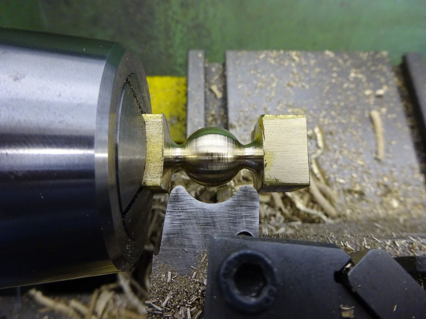
              You could do a ball end via some calculations – turn a series if steps and then smooth them out with a file. it's possible to make the steps a few thou short of the sphere and use the bottom corners as witness marks – file down to them evenly and then carefully remove them via more careful filing.

              Lock the saddle and use the compound slide for that axis.

              Accurate balls via a ball turning attachment need careful setting up.

              The other alternative is a file and radius gauges but smoothed out steps are easier.

              Rather than a file a graver can also be used. Sometimes a piece of bar held in the tool post can be used as a rest.

              John

              Edited By John W1 on 21/12/2015 11:23:27

              Edited By John W1 on 21/12/2015 11:25:46

              #217298
              Brian John
              Participant
                @brianjohn93961

                I was thinking about doing it by eye but I have dismissed that idea.

                How about this tool ; it has a 12mm shank and my lathe will take a 13mm shank.

                **LINK**

                But I am not sure why it is unsuitable for a Sieg C2 ''insufficient clearance behind the spindle''. That reason is not clear to me ? Anyway, it is only for larger lathes. Does anybody make anything similar for smaller lathes ?

                Edited By Brian John on 21/12/2015 11:29:45

                #217304
                Brian John
                Participant
                  @brianjohn93961

                  Hopper : so the gap between the piston and the glass tube is necessary so I will make the piston 12.5mm as per the drawings. It looks like the displacement brass cylinder can be anything though ; it is marked as 14mm so I assume that this is not crucial at all (part #25).

                  Does the piston have to be aluminium and if so, why ?

                  I have seen many Stirling engines that do not use glass ; they use a metal tube. What metals are best for this job ?

                  Edited By Brian John on 21/12/2015 11:41:41

                  #217318
                  Ian S C
                  Participant
                    @iansc

                    Brian, what is the displacer piston made of? These are usually made hollow, and thin walled stainless steel is the ideal. I have seen some actually made from a smaller test tube, as long as you have a gap of (say) a mm.

                    The best of my engines have thin walled stainless steel for the hot cap, and the displacer, the final dimensions often(in my case)depend on what materials I have in the junk box.

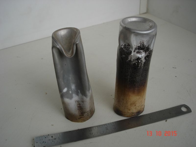
                    If the piston is aluminium, it's for weight (you don't want weight), aluminium is not the best stuff to use here, it conducts heat too fast, so that too much heat arrives as the cold end.

                    This is what happens to hollow aluminium displacers when you start to get some heat into things.

                    Ian S Cdsc01133 (800x600).jpg

                    #217323
                    Brian John
                    Participant
                      @brianjohn93961

                      Ian : the displacer piston is aluminium.

                      #217332
                      JasonB
                      Moderator
                        @jasonb

                        I think I said early on in this thread that a bit of freehand turning and a file applied to the revolving work will do fine for rounding over the end of teh piston, you could do it faster than you could set up a ball/radius attachment.

                        An alternative is to grind a HSS toolbit with a 1/4 circle anmd apply that to the piston

                        Or buy a bit of gauge plate (ground flat stock) drill a 12.5mm hole in it, cut away what you don't want and the heat & quench.

                        Edited By JasonB on 21/12/2015 13:12:56

                        #217389
                        Brian John
                        Participant
                          @brianjohn93961

                          I have not had much luck with freehand work in the past but aluminium is cheap so I will give it a go once I finish boring the cylinders.

                          #217394
                          Brian John
                          Participant
                            @brianjohn93961

                            I bored out the three work cylinders (part #26) today. Yes, I made three because I needed to practise my recess cuts ! The first one I attempted to drill and ream using my newly arrived 10H7 reamer…what a mess. It must be a poor quality reamer as it did not leave a smooth finish on the inside. I have bought smaller reamers (2H7, 3H7 and 6H7) from this Chinese company before and had no problems. Maybe smaller sizes are easier to make ?

                            I found that it had reamed undersize anyway (9.8mm) so I was lucky and cleaned it up with the boring bar to finish at 10mm. I did the other two with the boring bar after drilling out to 9mm with stub drills.

                            The boring bar is the way to go although I have to use auto feed. I cannot get a smooth finish on manual feed.

                            #217400
                            Martin Connelly
                            Participant
                              @martinconnelly55370

                              You could use stepped roughing to get the basic curve done on the piston then finish with a file. See ballcut.zip here:

                              **LINK**

                              Martin

                              #217520
                              Brian John
                              Participant
                                @brianjohn93961

                                The parts list show the working piston (part #15) as ''Rotguss'' which I have googled and come up with ''red brass''  This is also classified as a type of both bronze and brass according to Wikipedia. All the other brass parts are listed as Ms58. Why is this piston made of this type of brass/bronze ?

                                Edited By Brian John on 23/12/2015 05:42:16

                                Edited By Brian John on 23/12/2015 05:42:38

                                #217526
                                Andy Holdaway
                                Participant
                                  @andyholdaway

                                  Red brass is a gunmetal. I presume from the inclusion of lead and tin it provides an amount of lubrication for the piston.

                                  #217530
                                  pgk pgk
                                  Participant
                                    @pgkpgk17461
                                    Posted by Andrew Holdaway on 23/12/2015 09:01:27:

                                    Red brass is a gunmetal. I presume from the inclusion of lead and tin it provides an amount of lubrication for the piston.

                                    ..when the q was posed i looked up 'red brass' as a gunmetal but nothing re lead in it and couldn't see why the difference with brass would help lubrication. Logic suggested perhaps better able to cope with condensation/corrosion compared to brass but then often the power side cylinders are made of brass which negates that theory?

                                    Is gunmetal more or less prone to 'tarnish' than brass?

                                    Edit…  a carbon piston makes for sense..

                                    Edited By pgk pgk on 23/12/2015 09:30:42

                                    #217540
                                    Ajohnw
                                    Participant
                                      @ajohnw51620

                                      It's the fit the drawings indicate between cylinders and pistons that is most important Brian not the precise sizes some slight variation on those wont matter.

                                      The other aspect that matters on stirling engines is the phasing of the pistons. That usually corresponds to the distance between holes in linkages.

                                      Stainless is sometimes used for the hot cylinder but borosilicate test tubes have lower thermal conductivity so may well be a better choice.

                                      Red brass etc – it's more capable of running in close proximity to a cylinder than say aluminium or even mild steel which might well pick up and bind.

                                      I assume that little program some one posted a link to calculates the step sizes to produce a radius. It's an easy way of doing it pretty precisely and finishing with a file after that is done is easy. Some people do the same thing on milling machines for the same reason. I might be tempted to buy a cutter. It's also possible to produce a decent rad by turning various angle chamfers and then smoothing with a file. Best for situations where the actual value doesn't matter too much.

                                      John

                                      #217545
                                      Brian John
                                      Participant
                                        @brianjohn93961

                                        I tried to buy a single cut smooth file for the final shaping of the aluminium displacement piston but I could not find one anywhere in Cairns. I will just rough it out with my double cut files and finish off with wet and dry sandpaper if I get the shape right.

                                        #217550
                                        Andy Holdaway
                                        Participant
                                          @andyholdaway

                                          pgk pgk, I know you shouldn't believe everything you read on the internet, but this from Wikipedia:

                                          "Red brass used to produce pipes, valves, and plumbing fixtures, and is considered to offer a good mixture of corrosion resistance, strength, and ease of casting.[6] It typically contains 85% copper, 5% tin, 5% lead, and 5% zinc."

                                          #217553
                                          Ajohnw
                                          Participant
                                            @ajohnw51620
                                            Posted by Brian John on 23/12/2015 11:03:08:

                                            I tried to buy a single cut smooth file for the final shaping of the aluminium displacement piston but I could not find one anywhere in Cairns. I will just rough it out with my double cut files and finish off with wet and dry sandpaper if I get the shape right.

                                            With aluminium you are probably better off not using a super smooth file. It's rather soft so can clog up the file. The actual size of the cut on a file can vary with the size of the file too. Smaller – finer. I need to get a couple of coarser cut small files off Aminster.

                                            A drop of oil will help with the wet and dry. If I'm feeling manic I sometimes finish with a little abrasive rubber like block that is used for cleaning pcb contacts. Quick and easy and they last a long time. It's a very fine abrasive as pcb contacts are often gold plated. Metal polish will do it too but rags can catch in chucks which can result in lost fingers.

                                            John

                                            #217567
                                            steamdave
                                            Participant
                                              @steamdave
                                              Posted by John W1 on 23/12/2015 11:45:29:

                                              snip … With aluminium you are probably better off not using a super smooth file. It's rather soft so can clog up the file. The actual size of the cut on a file can vary with the size of the file too. Smaller – finer. I need to get a couple of coarser cut small files off Aminster.

                                              John

                                              Chalk rubbed on a file helps to prevent clogging. Oh for the good old schooldays days with chalk and a blackboard!

                                              Dave
                                              The Emerald Isle

                                              #217613
                                              Brian John
                                              Participant
                                                @brianjohn93961

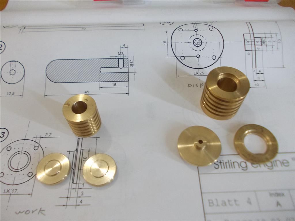
                                                I made the cylinder covers for the work and displacement cylinders today. I made two for the work cylinder because things were going so well !

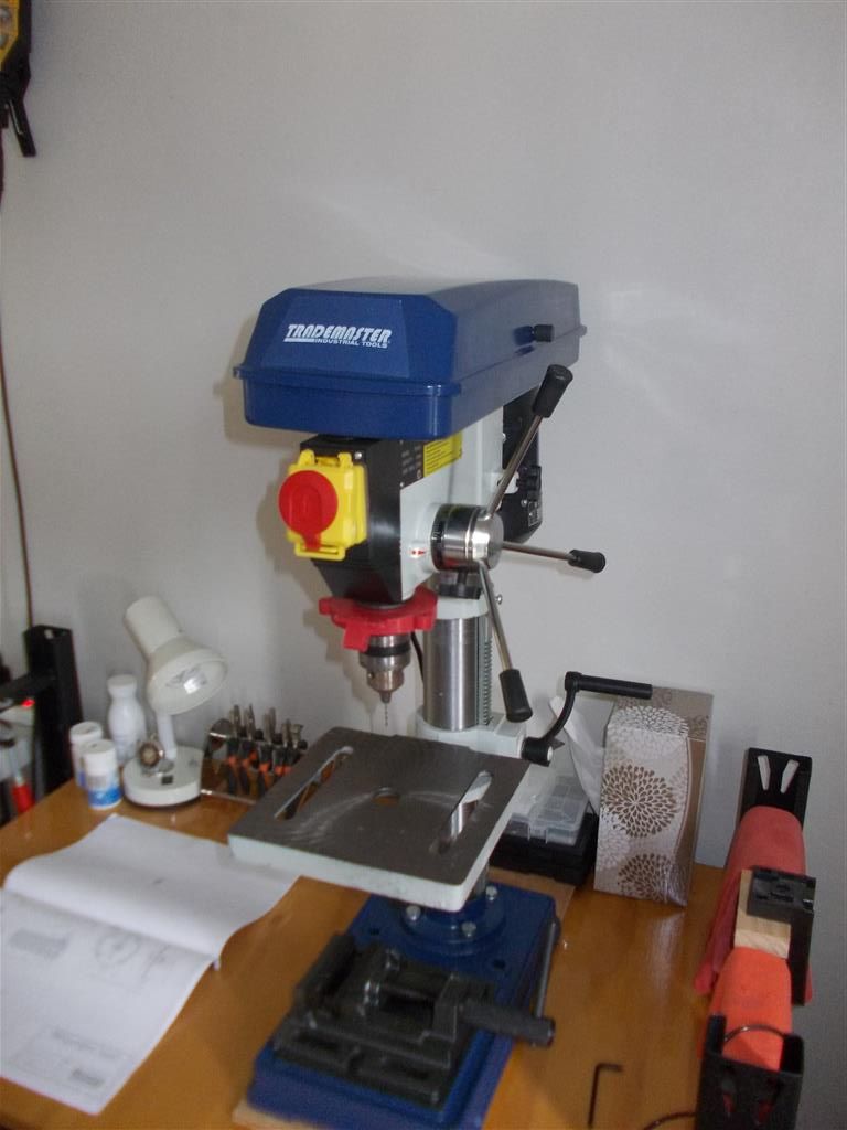
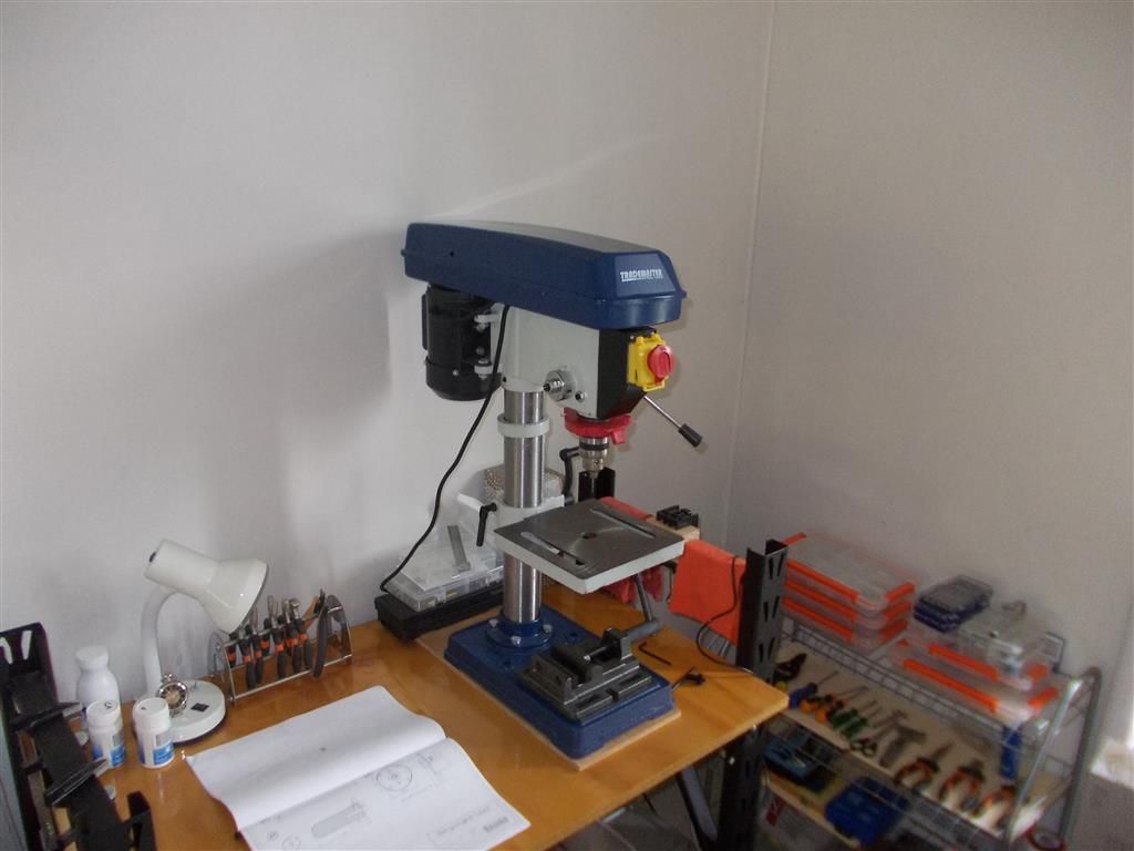
                                                I also treated myself to a new Trademaster bench drill. It was the display model and the last one they had so I thought I had better grab it now. The improved quality over my last bench drill is obvious. When I turn it on the drill bit does not wobble all over the place : a 1.5mm drill bit will actually drill a 1.5mm hole unlike the last machine.

                                                At some stage I am going to have to cut the glass test tube to size. What is your favourite way of cutting glass tubing ? I was think of doing it in the lathe with a triangular file.

                                                collars and covers.jpg

                                                trademaster 1.jpg

                                                trademaster 2.jpg

                                                Edited By Brian John on 24/12/2015 06:18:28

                                                Edited By Brian John on 24/12/2015 06:20:02

                                                Edited By Brian John on 24/12/2015 06:22:10

                                                #217624
                                                maurice bennie
                                                Participant
                                                  @mauricebennie99556

                                                  Hi Brian , The easy way is to scratch the tube ONE third the way round , we had what we called a glass knife, made I think of tungsten carbide but anything that will scratch the tube will work,this will work on tube up to half inch. wear leather gloves,or as I did a duster in each hand and grip the tube ,one hand on each side of the mark and the mark on top, thumbs on top then pull and bend at the same time downwards (each thumb close to the mark) wear goggles just in case . I have broken off pieces from a five foot tube 3/8 " diameter and four inches long . This all depends on diameter and length to be broken .I was once working as a glass blower making apparatus for a laboratory. Hope this helps ,and do not be frightened of it .

                                                  best wishes and a happy yuletide Maurice.

                                                  .

                                                  Edited By maurice bennie on 24/12/2015 10:02:06

                                                  #217626
                                                  Bob Unitt 1
                                                  Participant
                                                    @bobunitt1
                                                    Posted by John W1 on 23/12/2015 11:45:29:Metal polish will do it too but rags can catch in chucks which can result in lost fingers.

                                                    Woodturners use something called 'safety cloth' for polishing, it tears if it catches rather than dragging you into the chuck. I see no reason why this shouldn't work with metal polish too.

                                                    #217627
                                                    maurice bennie
                                                    Participant
                                                      @mauricebennie99556

                                                      Hi Brian again ,The only other way is to use a diamond wheel .Not got mind in gear this morning. Maurice.

                                                    Viewing 25 posts - 176 through 200 (of 764 total)
                                                    • Please log in to reply to this topic. Registering is free and easy using the links on the menu at the top of this page.

                                                    Advert

                                                    Latest Replies

                                                    Home Forums Stationary engines Topics

                                                    Viewing 25 topics - 1 through 25 (of 25 total)
                                                    Viewing 25 topics - 1 through 25 (of 25 total)

                                                    View full reply list.

                                                    Advert

                                                    Newsletter Sign-up