Stirling Engine : Laura

Advert

Stirling Engine : Laura

Home Forums Stationary engines Stirling Engine : Laura

Viewing 25 posts - 151 through 175 (of 764 total)
  • Author
    Posts
  • #215031
    Neil Wyatt
    Moderator
      @neilwyatt

      > I wonder if some of the problems with fine taps is down to the depth they are used to.

      Must agree, I'm sure that most 10BA studs out there go in about 10mm…

      Neil

      Advert
      #215039
      Ajohnw
      Participant
        @ajohnw51620
        Posted by Neil Wyatt on 03/12/2015 21:06:33:

        > I wonder if some of the problems with fine taps is down to the depth they are used to.

        Must agree, I'm sure that most 10BA studs out there go in about 10mm…

        Neil

        Maybe it's down to model " ? engineers ? "

        Must admit though thinking back to work on car engines studs do go in further than the engagement length of nuts.

        That's interesting as the reason for nut thickness relates to strength. When tightened both distort due to pitch errors and it's argued that too much engagement length doesn't increase the holding power at all as there will be more distortion.

        I have a feeling I will be getting machinery's out to see what they have to say on the subject of studs. Maybe longer engagements are used to help keep them vertical if knocked. 1D from that point of view would be marginal. I'd guess 2 maybe 2 1/2 D.
        indecisionI have never designed anything at work that uses studs. Plenty of thing that use unbrako's – press tools and jigs and fixtures etc.

        John

        #215042
        Ajohnw
        Participant
          @ajohnw51620

          They state 1 1/4 D for ferrous and brass, hardness <= or > 160 BHN and 2 1/2 D for other none ferrous, soft stuff such as aluminium and copper I assume.

          LOL So much for my guess.

          frownThey also mention that BS messed up the tolerances on studs such that they might turn out not to be an interference fit in the hole – explains all of those irritating ones that unscrewed rather than staying in place when the nut was removed.

          John

          #215073
          Ian S C
          Participant
            @iansc

            In the small sizes I have a number of taps in the Thread Flow type, no flutes, they form the thread in ductile metals rather than cut them.
            Ian S C

            #215241
            Brian John
            Participant
              @brianjohn93961

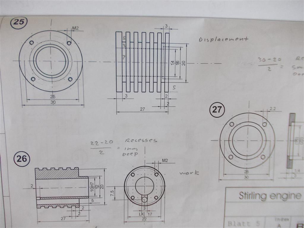
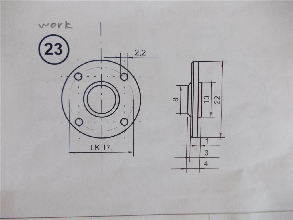
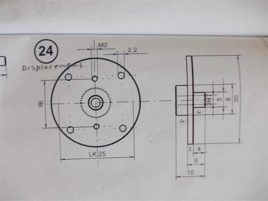
              I made a start on the cylinder covers today but I am having some problems working out the correct order of operations. How would you tackle parts 23 and 24 ?

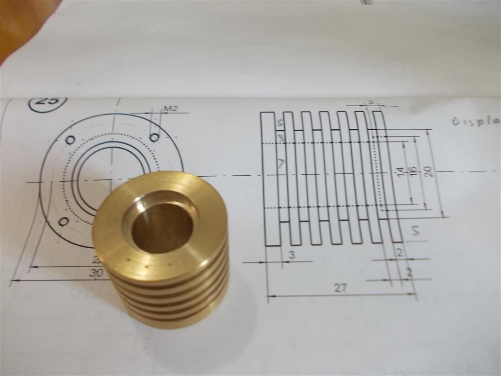
              I am also puzzled by the measurement for the displacement cylinder cover (24) where it says 8mm diameter. If this is to fit in the displacement cylinder then I would have thought it should be 14mm (see part 25) ?

              NOTE : I have just worked four night shifts so maybe my brain is a bit fuzzy : )

              cylinder plans.jpg

              work cylinder cover plans.jpg

              displacement cylinder cover plans.jpg

              #215245
              JasonB
              Moderator
                @jasonb

                Part 23

                Hold material in 3 jaw, face off, cut the 10mm x 1mm spigot, turn outer dia if required, saw/part off.

                Ideally use soft jaws but a syou don't have these put packing between chuck and work with the just machines face against packing – remove packing before turning on. Face to length, using a tool with 45deg face cut the 8mm decorative spigot, chamfer the outer edge. Mark out 4 lines while held in the lathe and also the hole PCD.

                #216971
                Brian John
                Participant
                  @brianjohn93961

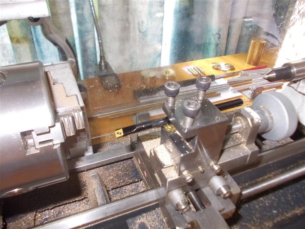
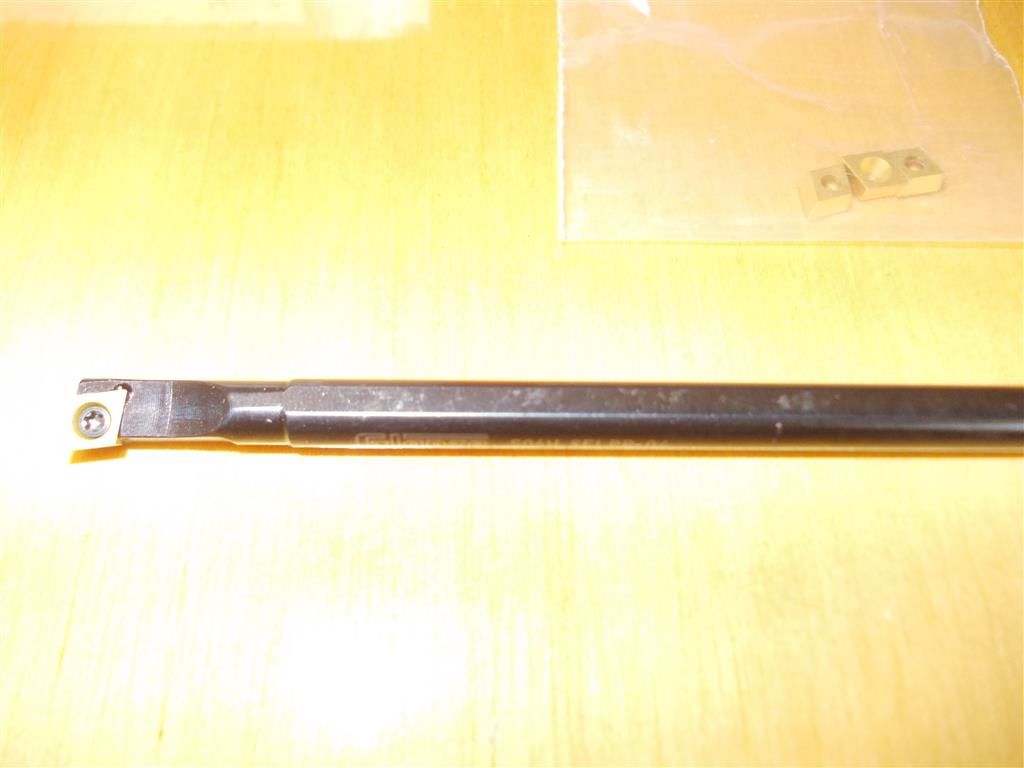
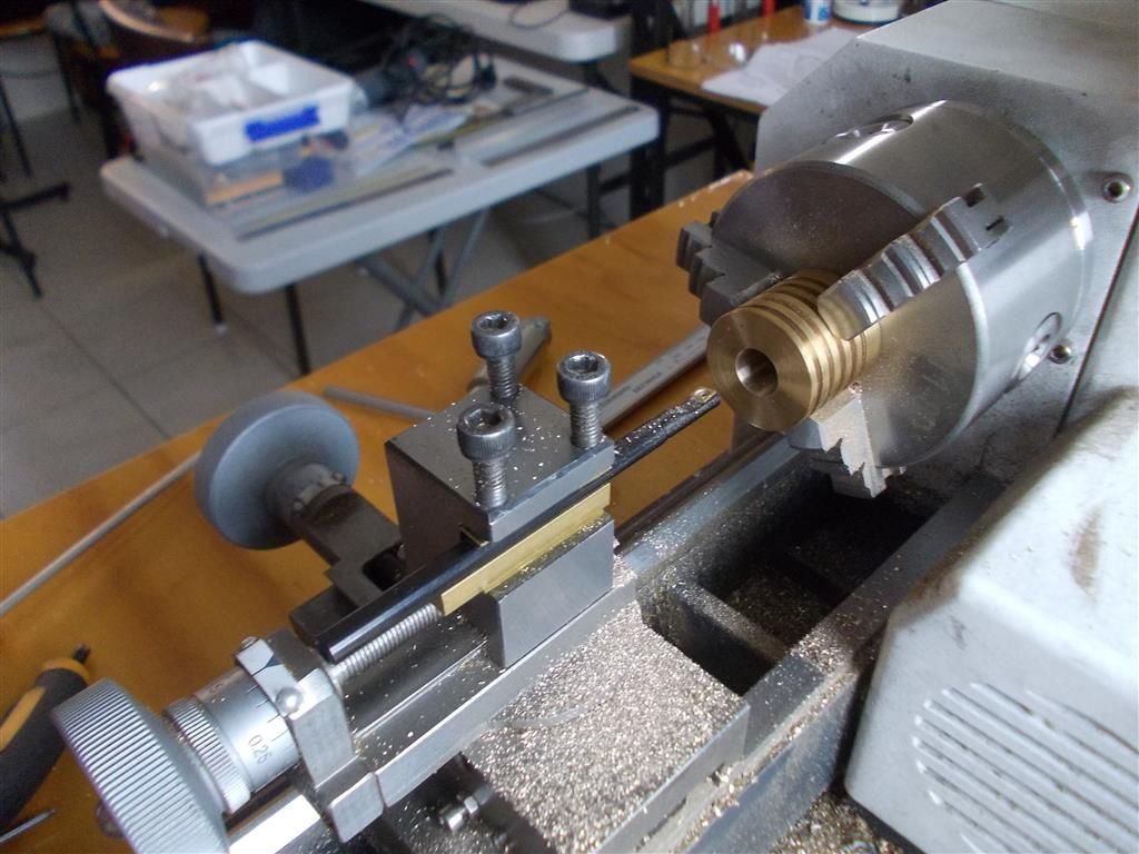
                  I have been in Brisbane for the last nine days and now I am back in Cairns so it time to get back on the lathe.The boring bar arrived yesterday. I had assumed that this could be held directly in the tool post using suitable packing to raise it to the correct height. But now I have a feeling that this should be mounted in a special holder. I just cannot get it to sit right.

                  boring bar 1.jpg

                  boring bar 2.jpg

                  Edited By Brian John on 19/12/2015 06:24:26

                  #216983
                  Martin Connelly
                  Participant
                    @martinconnelly55370

                    Not sure what you mean by sitting right, the flats on the bar will set the insert to the correct angle. You may need to set the tip slightly above centre line though. I would also suggest a bit of packing on the top face of the bar, it will quickly get chewed up by the clamping screws otherwise. Boring bars need to be set to the minimum necessary stick out for the job being done. This means a lot of clamping and releasing to damage the bar if not protected.

                    If you are using a boring bar with an insert close to the minimum diameter it will fit in you need to look at where the bottom corner of the insert is to make sure it is not rubbing, this is why the tip needs raising sometimes.

                    Martin

                    #216989
                    Brian John
                    Participant
                      @brianjohn93961

                      The insert is not sitting horizontally. I will put some packing on the top as you suggested. Perhaps the clamping screws were throwing it out of alignment.

                      Why does the tip have to be set slightly above the centre line ?

                      #216992
                      JasonB
                      Moderator
                        @jasonb

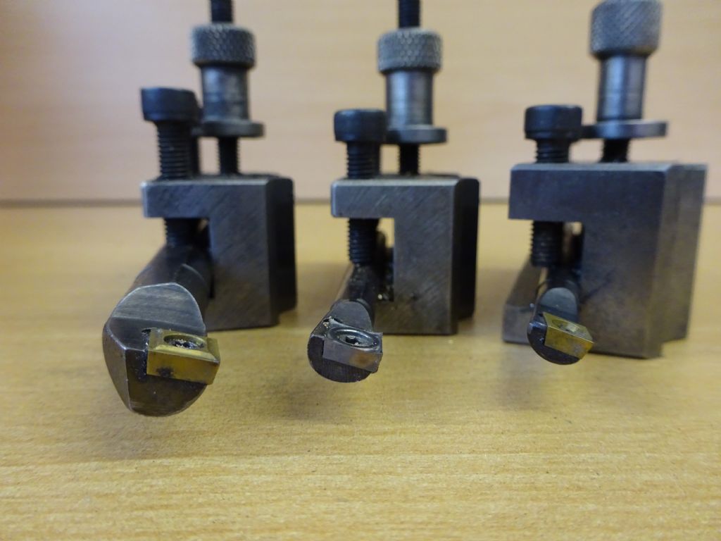
                        Brian the insert should point down, the flats on teh toolholder will be level when clamped.

                        I set them so the point of the tip is on ctr line then you can face across the bottom of a blind recess.

                        dsc00501.jpg

                        Edited By JasonB on 19/12/2015 09:41:30

                        #217004
                        Ajohnw
                        Participant
                          @ajohnw51620

                          The tips should be a SLIGHTLY above centre so that if the bar bends it doesn't dig further into the work making it bend more and dig in even further etc. This is the opposite of turning outside diameters where if the tool bends at all it takes less material providing it's exactly on or a little below centre. Here it's more a case of setting slightly below centre to be more sure that it isn't above. Just good practice in other words unless some one wants to deliberately turn with the tool above centre.

                          Boring bars are far more likely to bend so are more critical in this respect. The amount needed depends on the bar and on the size of the cut.

                          John

                          #217005
                          Brian John
                          Participant
                            @brianjohn93961

                            Oh, so it IS supposed to be tilted like that ? Thank you…..I thought I was doing something wrong.

                            #217040
                            JasonB
                            Moderator
                              @jasonb
                              Posted by John W1 on 19/12/2015 10:47:32:

                              The tips should be a SLIGHTLY above centre

                              John as these are the standard SCLCR type tools which are designed for boring and facing how do you manage to take a facing cut if the tip is set above ctr height? Running above ctr is a sure fire way to chip the tip as it gets pushed up by the cone left in teh middle of the work.

                              You would not be able to make cuts like this with it above ctr

                              #217045
                              Ajohnw
                              Participant
                                @ajohnw51620

                                I see them as more for facing shoulders in bores Jason not facing the bottom of blind holes. However on a shallow one such as you show there would be little overhang and not much chance of the tool deflecting.

                                I can think of a number of occasions when I have had to set a tool significantly over centre just due to the size of cut being taken and the size of the bar that has to be used so even the term SLIGHTLY needs qualifying. I would generally see it as meaning thou's when boring or during straight turning. When boring deflection can introduce chatter but often the best solution is to turn the speed right down.

                                All messed up when deliberately turning well above centre using tools with excessive amounts of clearance but that is a rather specialised subject and needs a pretty rigid set up. That is the other aspect of tool setting. Below centre reduces the clearance angle when boring. Above centre reduces it when turning. This can be pretty critical on low diameter parts

                                John

                                #217124
                                Brian John
                                Participant
                                  @brianjohn93961

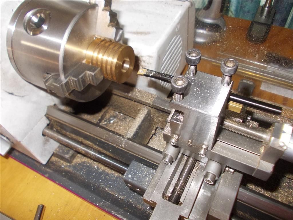
                                  Well, that went very well : my first use of the boring bar did not throw up any real problems. I used a piece of 6mm brass bar that came with the stirling engine kit to jack up the height and I put one shim underneath it to raise it slightly above centre and one shim on top of the boring bar to protect it as per the above advice.

                                  I was not getting a smooth finish with manual feed but the auto feed gives a perfect finish. I made the recess on the top of the cylinder too wide at 17mm (supposed to be 16mm). I am not sure what went wrong there ! Anyway I can just adjust the collar to suit when I make it.

                                  This is also my first use of an indexable tip. They do cut very nicely.

                                  NOTE : where can I buy 6mm square brass bar in Australia or the UK ? My usual suppliers only have 1/4 inch X 1/4 inch. I will need more for the Stirling engine kit as not enough has been supplied.

                                  boring bar 3.jpg

                                  boring bar 4.jpg

                                  boring bar 5.jpg

                                  Edited By Brian John on 20/12/2015 06:27:15

                                  Edited By Brian John on 20/12/2015 06:52:35

                                  Edited By Brian John on 20/12/2015 06:52:52

                                  #217132
                                  Andy Holdaway
                                  Participant
                                    @andyholdaway

                                    Brian, you should have more than twice the amount of 6mm square that you need in the kit. It's only used for parts 12 (12mm long) and 18 (6mm long) and my kit came with a piece about 60mm long.

                                    I've been following this thread with interest as I am also in the middle of building one of these – my first attempt at any form of model engineering in about 40 years. I was also confused by the boring bar tip angle, but I have a friend who is a 'proper' engineer who put me right.

                                    You may have to have a think about the recess that you've made 17mm instead of 16mm – it retains the O-ring that forms the seal for the glass cylinder. Even at 16mm it's not a tight fit!

                                    Edited By Andrew Holdaway on 20/12/2015 09:50:11

                                    #217133
                                    Brian John
                                    Participant
                                      @brianjohn93961

                                      Thank you for that Andrew. I was not aware that the recess was for the O ring. I will have to do it again. I always expect to make at least two attempts before I get it right which is why I need the extra brass


                                      Edited By Brian John on 20/12/2015 10:07:24

                                      #217137
                                      Ajohnw
                                      Participant
                                        @ajohnw51620

                                        I don't know what the 6mm sq bar is for Brian but the fact that 1/4" sq is 0.014" / 0.35mm bigger might not matter at all. I have a very good none ferrous supplier not far from me and the bulk of their stock is imperial. Over the past 5 years or so they have added some metric stock but only where some one wants significant amounts of it or on certain materials where it is only supplied that way now. The only one I can think of off hand is oddly cast iron. They keep a limited amount of that.

                                        This area is a problem you might often come across so the easiest answer is to consider what are the important aspects of a design. As far as engines go that is the fits of certain parts and timing associated parts.

                                        John

                                        #217143
                                        Martin Connelly
                                        Participant
                                          @martinconnelly55370

                                          I would not be too worried about the diameter where the o ring fits. If it is snug on the cylinder and trapped between two other parts then it will do its job. If however it does need a accurately sized diameter then consider soldering in a ring to machine back to size. It may require a little more machining off the recess before the ring is soldered in depending on where the join line falls.

                                          Martin

                                          #217160
                                          Brian John
                                          Participant
                                            @brianjohn93961

                                            Martin : yes, I have been thinking about how I could salvage the piece. It is always worth trying these things just to see if it can be done. Something is always learnt in the attempt.

                                            #217183
                                            Brian John
                                            Participant
                                              @brianjohn93961

                                              Andrew : I have just looked and there are two O rings in my kit but they are both 20mm in diameter. They do not fit in that recess as they are too big for either 16mm or 17mm. How big are your O rings ?

                                              My instructions say '' part 42  1 X O ring glass tube 16mm 2mm filament''. I definitely do not have that. They are easily obtained on ebay though.

                                              Edited By Brian John on 20/12/2015 13:38:33

                                              #217212
                                              Andy Holdaway
                                              Participant
                                                @andyholdaway

                                                Brian, I also had two in the kit and they are indeed 20mm x 2mm. I confess I didn't measure the O ring, I just shoved it in the recess – it fits, and gives the seal a bit more bulk.

                                                I've just checked the drawing, and the recess in the cylinder cap is 20mm, so the O ring sits nicely in the cap and I presume then distorts down into the cylinder recess to effect the seal. So I apologise for sending you off on the wrong track – the recess in the cylinder cap is to house the O ring, which makes the recess in the cylinder a lot less critical.

                                                Andy

                                                #217266
                                                Brian John
                                                Participant
                                                  @brianjohn93961

                                                  I bored out another displacemnt cylinder today and I also made the collar for the glass tube (part 27). These boring bars are useful things : how did I manage without one !

                                                  1. I must admit I am a bit puzzled about the 16mm recess in the displacement cylinder and the 16mm recess in the collar. Is this just to take the excess from the O ring ?

                                                  2. If you had to make a cylinder with a 10mm bore, what would you use : drill to 9.8mm and ream out to 10mm or a boring bar ?

                                                  Edited By Brian John on 21/12/2015 06:11:25

                                                  #217269
                                                  JasonB
                                                  Moderator
                                                    @jasonb

                                                    I would bore it unless it was very long which would mean the boring bar would have to hang too far out the toolpost.

                                                    J

                                                    #217273
                                                    Brian John
                                                    Participant
                                                      @brianjohn93961

                                                      I am also a bit puzzled about Stirling Engines in general : the displacement cylinder has a 14mm bore, the glass cylinder is 13mm ID and the piston is 12.5mm. It would seem that the bore of the displacement cylinder is not crucial as nothing is touching it. And I would have thought the piston would have to be a tighter fit inside the glass tube ?

                                                      Actually the parts list show the piston (part #22) as 13mm X 45mm but the drawing shows 12.5mm X 45mm. I do not think 12.5mm can be correct as this would surely be too loose in the 13mm ID glass tube ?

                                                      Edited By Brian John on 21/12/2015 08:41:28

                                                    Viewing 25 posts - 151 through 175 (of 764 total)
                                                    • Please log in to reply to this topic. Registering is free and easy using the links on the menu at the top of this page.

                                                    Advert

                                                    Latest Replies

                                                    Home Forums Stationary engines Topics

                                                    Viewing 25 topics - 1 through 25 (of 25 total)
                                                    Viewing 25 topics - 1 through 25 (of 25 total)

                                                    View full reply list.

                                                    Advert

                                                    Newsletter Sign-up