Stirling Engine : Laura

Advert

Stirling Engine : Laura

Home Forums Stationary engines Stirling Engine : Laura

Viewing 25 posts - 626 through 650 (of 764 total)
  • Author
    Posts
  • #233503
    Brian John
    Participant
      @brianjohn93961

      A brand name might be very useful. I got the feeling that some people answering the phone today did not understand the term ''flux'' !

      What is the purpose of a few drops of detergent when mixing up the flux paste ?

      Advert
      #233504
      Michael Gilligan
      Participant
        @michaelgilligan61133
        Posted by Brian John on 06/04/2016 08:30:06:

        What is the purpose of a few drops of detergent when mixing up the flux paste ?

        .

        'Wetting Agent' … reduces surface tension.

        MichaelG.

        Edited By Michael Gilligan on 06/04/2016 08:38:52

        #233513
        Ajohnw
        Participant
          @ajohnw51620
          Posted by Brian John on 06/04/2016 08:30:06:

          A brand name might be very useful. I got the feeling that some people answering the phone today did not understand the term ''flux'' !

          What is the purpose of a few drops of detergent when mixing up the flux paste ?

          There should be a range of silver solder fluxes available where you would normally get them from Brian. Might be best to forget mentioning stainless and just picking the one with a melting point similar to the one Jason mentioned.

          If no joy it might be worth trying borax which melts at 750C which is higher than tenacity 5. Some I believe use this for silver solder anyway.

          Id' be cautious about the detergent. It doesn't take much. Not something I have done but I'd add 1 maybe 2 DROPS of it to 500ml of water and then use that to mix the flux. I suspect there might be problems if drops are added to a small flux mix of say a couple of teaspoons which might be all you need.

          John

          #233611
          Brian John
          Participant
            @brianjohn93961

            I received a phone call from Blackwoods this morning : they have CIG WELD 321850 flux which is suitable for stainless steel. I did ask about Tenacity 5 but I was informed that product is only available in the UK and is not sold in Australia. I thought that was odd as I can buy Tenacity 4,6 and 20 here. Anyway, I will be going to Blackwoods to get the CIG flux today.

            http://www.cigweld.com.au/product/brazing-fluxes/comweld-gp-sba-flux/

            This stainless steel flux works with medium and low grades of silver solder. The silver solder I use for brass and copper is 245 grade. I am not sure what percentage of silver is in this but I will have to find out.

            Edited By Brian John on 07/04/2016 02:29:10

            #233614
            Brian John
            Participant
              @brianjohn93961

              Wrong product ! CIG 321850 is for low or medium percentage silver solder. I use 245 grade which is 45% silver solder so I need CIG 321840 SBA flux #2 for high percentage silver solder which I will buy tomorrow :

              **LINK**

              I am certain that many of the companies I called the other day would have had this on the shelf but many of them did not even know what I meant when I used the term ''flux''. My fault, lesson learnt : do your homework first and do not rely on anybody knowing what you are talking about !

              Today I have cut the stainless steel pipe using a plumbers pipe cutter. My large hacksaw was just making a mess of it. I then trimmed up the ends of the pipe in the lathe. Now I can turn my attention to the brass collar. I have a number of options here : I can use an O ring or just rely on a good fit between the collar and the D cylinder to affect a seal. I think O rings would only complicate things.

              #233751
              Brian John
              Participant
                @brianjohn93961

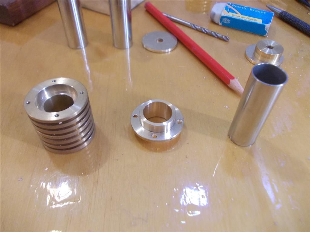
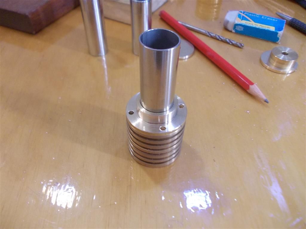
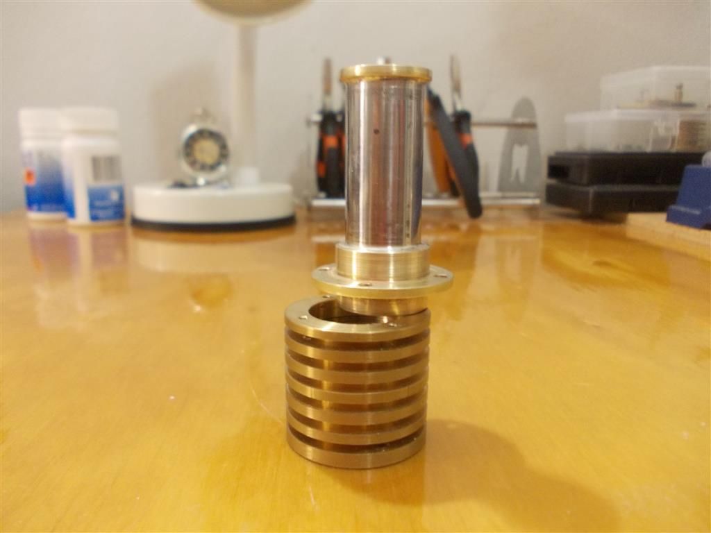
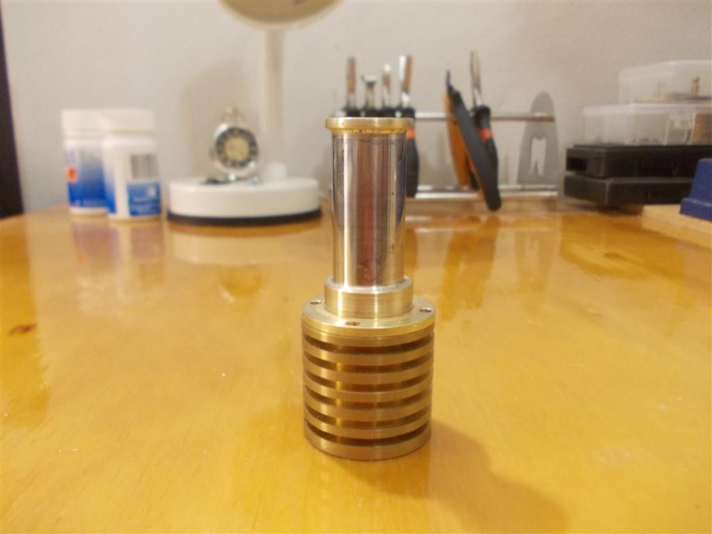
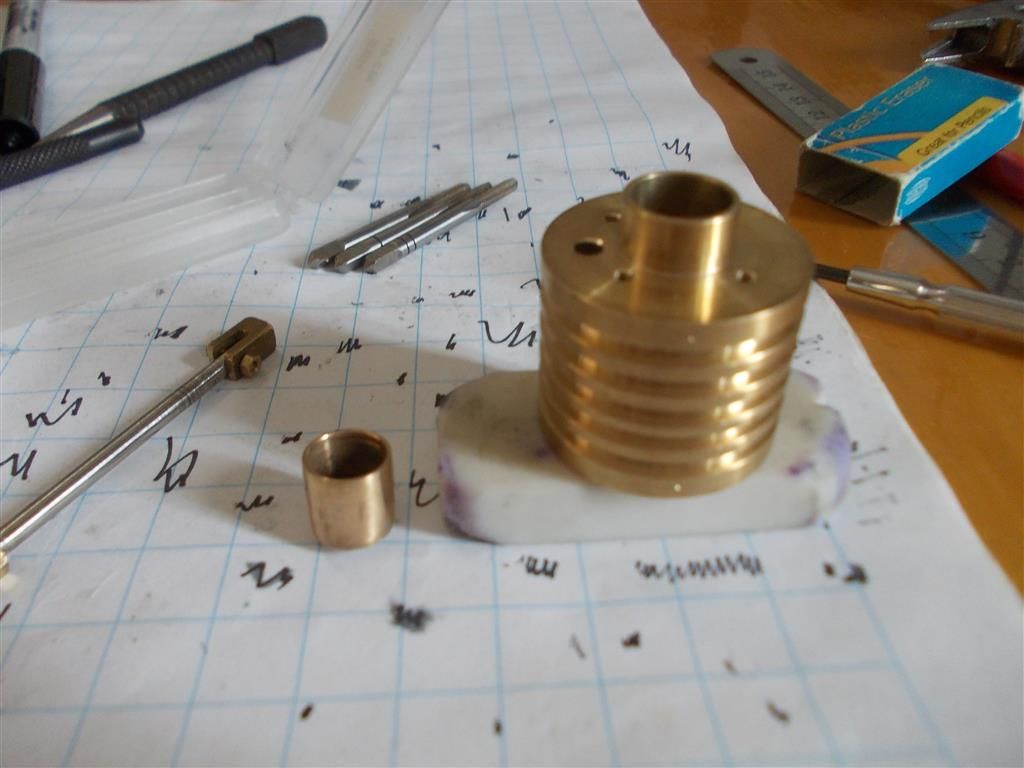
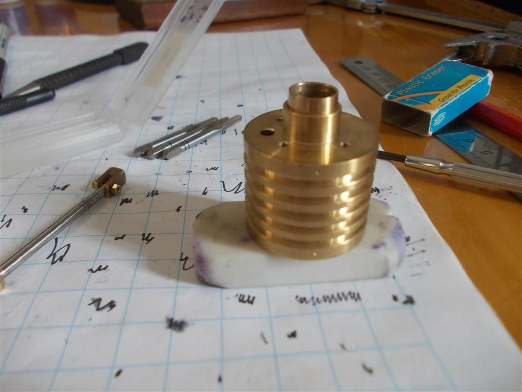
                I made the collar for the hot cap today. As usual I made life difficult for my self by drilling and tapping the D. cylinder first. I should have drilled the holes in the collar first but I always forget to do that ! Anyway, it all worked out in the end so now all I need to do is make the brass end cap. I am still thinking about the best shape for that.

                Silver soldering stainless steel :

                1. I now have the correct flux. How is the flux removed once the job is done ? It says to use a hot caustic soda dip. The bleach I have in the bathroom is 4g/L Sodium Hydroxide (NAOH) ; would this do the job ?

                There is also the option of a wire brush and hot water to clean the flux….. perhaps that might be safer.

                2. Should the stainless steel be roughened up with sandpaper or a wire brush prior to applying the flux ?

                hot cap 1.jpg

                hot cap 2.jpg

                Edited By Brian John on 08/04/2016 07:58:13

                #233752
                JasonB
                Moderator
                  @jasonb

                  You can use the same acid you have used on your silver soldered joints before but it takes longer, I find patio cleaner shifts HT5 very well so have not tried caustic soda. Either way a small wire brush will help.

                  Yes wirebrush the surface to clean it does not need to be rough.

                  #233789
                  Ian S C
                  Participant
                    @iansc

                    On my wee motor I used brass to braze the steel flange onto the steel case from a NiCad battery, flux Borax, that's the method I use for most of my brazing. For the hot end joint, I take it to my tame TIGer, and let him stick it together. Brian that looks great. A wee tip, when you braze the flange on, I find it a good idea to have a mm or two through to the other side to locate in the hole it's being mounted to. For a small hot cap like this, three screws are enough if you are like me and prefer to tap as few holes as you can.

                    Ian S C

                    #233801
                    Brian John
                    Participant
                      @brianjohn93961

                      I think the end cap will go inside the tube about 2mm. I will make the end cap about 3mm larger in diameter than the tube so that I have a bit of a ''lip'' to solder it to. I am still thinking about it all.

                      I drilled and tapped for four holes because I am using the pre-drilled cylinder holders as a template for the position of the holes. So much easier to drill the holes in the collar first but I always forget to do this !

                      #233841
                      Brian John
                      Participant
                        @brianjohn93961

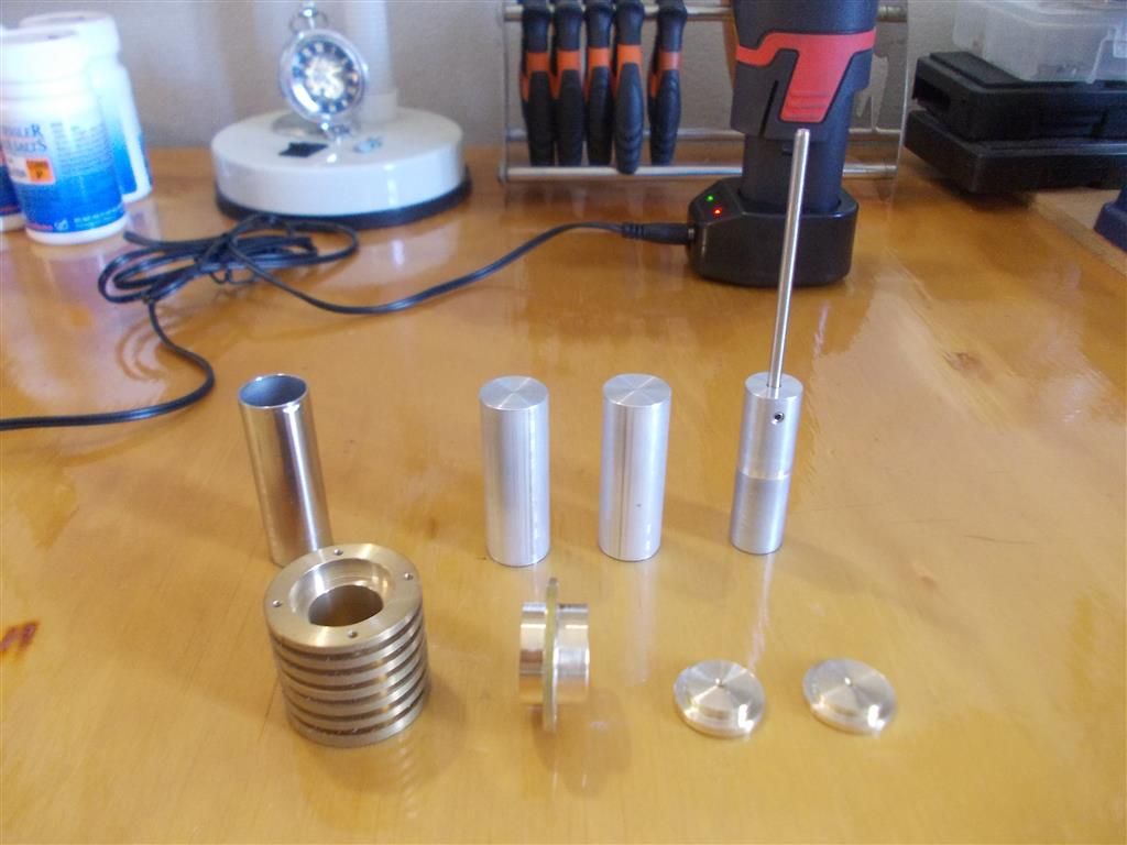
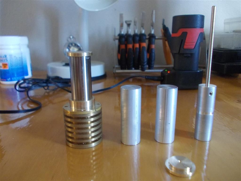
                        I machined two end caps today in case the soldering does not go as planned. I have also made one D. piston ; I will probably make a few more of various diameters to see which one works the best. I think my gas cylinder is less than half full so I need to buy some more gas before silver soldering everything together….hopefully tomorrow, weather permitting.

                        What about piston shape ? I am not using a glass tube so the D. piston does not have to be bullet shaped with a rounded nose but is a simple cylindrical shape the best for a Stirling engine ?

                        hot cap 3.jpg

                        hot cap 4.jpg


                        Edited By Brian John on 09/04/2016 07:19:40

                        Edited By Brian John on 09/04/2016 07:21:01

                        #233872
                        Ian S C
                        Participant
                          @iansc

                          I'v never used anything but a flat ended cylinder for a displacer. It looks as though you are making the displacer the same way as the original one, just minus the domed end. What is the bore of the hot cap?

                          Ian S C

                          #233873
                          Brian John
                          Participant
                            @brianjohn93961

                            The ID of the stainless steel tube is 14.5mm.

                            The original displacer had a round end glass tube held in position with  an O ring. It was a truncated test tube which does have a habit of blowing off sometimes.


                            Edited By Brian John on 09/04/2016 12:27:57

                            Edited By Brian John on 09/04/2016 12:28:25

                            #233999
                            Brian John
                            Participant
                              @brianjohn93961

                              The stainless steel silver soldering was successful. The flux is not a thick paste like the 602 flux used for copper and brass ; it is more liquid but it does the job. I made a bit of a mess by using too much solder and I had to use the boring bar to clean up the excess inside the tube. I washed the flux off with hot water and a wire brush then I put it in a NAOH 4g/l solution for an hour as per the instructions. Then it went into the citric acid for another two hours to try to clean it all up and get it shiny. The brass came up nice and clean but the stainless steel was still black after the soldering so I had to polish it up in the lathe using 1500 grit.

                              Is there a quicker way to clean stainless steel after soldering ?

                              hot cap 5.jpg

                              hot cap 6.jpg

                              Edited By Brian John on 10/04/2016 12:13:15

                              Edited By Brian John on 10/04/2016 12:15:48

                              #234453
                              Brian John
                              Participant
                                @brianjohn93961

                                I am just looking at the other Stirling engine that Bengs sell (John) ; that looks like a hot cap in the photos. The bar stock for that is either steel or stainless steel which will have to be drilled and bored. That could be a problem on my lathe. Can somebody cast their eye over the photos to confirm this please.

                                **LINK**

                                And what are those two rounded ''handles'' ? I thought they were handles but they do not look like they attach to anything that turns so I am a bit puzzled as to their purpose.

                                #234484
                                Ian S C
                                Participant
                                  @iansc

                                  I think you will find they are the air chambers on the water pump. They even out the flow of water in a reciprocating pump, sort of like a capacitor in an electrical circuit.

                                  That will keep you working for quite a while, but it will be a lovely motor when it's finished.

                                  Ian S C

                                  #234485
                                  Brian John
                                  Participant
                                    @brianjohn93961

                                    Air chambers…so they are hollow ? What would be the shape of the internal space ? I am wondering how they are made on the lathe.

                                    #234487
                                    Gordon W
                                    Participant
                                      @gordonw

                                      Air chambers on pump- On my two old pumps the air chambers are just hollow cast iron, only machining is the base flange. I guess the model ones are just drilled out.

                                      #234488
                                      JasonB
                                      Moderator
                                        @jasonb

                                        You can either just drill a straight cavity up from the mounting end which will do the job on a small engine like this.

                                        Or if feeling adventurous drill down from the top then use a tapered D bit to make a tapered hole and then silversolder on a cap, finally shape the outside.

                                        Does look like you have to machine it from solid stainless but you may be able to substitute a tube and solder something up if the lateh can't handle it.

                                        If you have a search for "Rider Ericsson pump" you will find plenty of photos of both full size and the many different scales of model. Don't know why Bengs did not call this one Eric?

                                        #234492
                                        Brian John
                                        Participant
                                          @brianjohn93961

                                          I will see how I go with my stainless steel tube/hot cap on the Laura engine. If that works then I know I can do something with this other engine too.

                                          #234604
                                          Ian S C
                                          Participant
                                            @iansc

                                            I don't think you really need to bore the air chambers, in this small size they will have virtually no effect.

                                            I see that the internal diameter of the displacer chamber is 14.5 mm, that's unfortunate, if it had been 16 mm this would have been a good place for a displacer made from an AA size NiCad, or alkaline battery case, and a AAA size is a bit too small at 10.5 mm.

                                            Ian S C

                                            #235857
                                            Brian John
                                            Participant
                                              @brianjohn93961

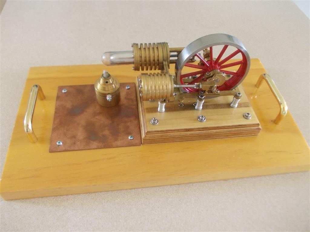
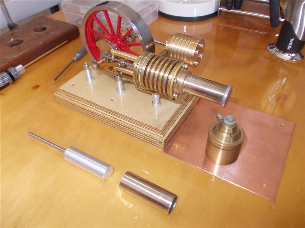
                                              Photo 1 is the finished product for Stirling engine #1, now finally mounted on its base.

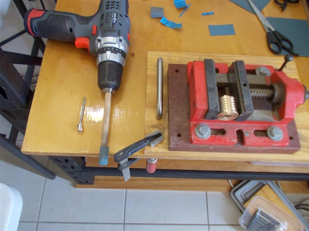
                                              Photo 2 is my home made brake hone for the power cylinder of engine #2. I used 1500 grit : it gave a nice smooth finish to the bore but I cannot say the cylinder to piston fit is any better. The bore is 10mm and the wooden dowel for the brake hone is 9.5mm. This gave a nice tight fit when the 1500 grit was inserted in the slot of the dowel and wrapped around it once. I may have been better off to put the hone in the tailstock chuck and the cylinder in the lathe chuck ; I may try that next time.

                                              finished product.jpg

                                              cylinder honing.jpg

                                              Edited By Brian John on 23/04/2016 11:38:15

                                              Edited By Brian John on 23/04/2016 11:40:42

                                              #235877
                                              Ian S C
                                              Participant
                                                @iansc

                                                Brian, I think you may have difficulty using a hone like that , and keep the bore parallel. The method I use is a wooden cylinder that just slides into the bore to be lapped, this cylinder is a bit over twice the length of the bore, plus a bit to grip in the lathe chuck, it has a saw slot down it's length with a wood screw in the end of the slot to expand it. The outside of the lap gets some fine grinding paste applied. Cover the lathe bed, and select a low speed, and in this case grab the cylinder being lapped with a gloved hand(it gets quite warm. Move the work back and forth, and I let it also slowly rotate. If you use a coarse grade of grit to start with, you should make a new wooden lap for the fine grit because the coarse grit gets embedded in the wood, and you can't be sure to get it out. Got two cylinders to do in the next few days.

                                                Ian S C

                                                #236100
                                                Brian John
                                                Participant
                                                  @brianjohn93961

                                                  Piston testing : the piston will drop straight through when the cylinder is unsealed. When the cylinder is sealed by placing it on an eraser and covering the side hole with my finger then the piston will take about 5 seconds to drop to the bottom under its own weight. Does this sound about right or should the piston not drop at all through the sealed cylinder ?

                                                  piston testing 1.jpg

                                                  piston testing 2.jpg

                                                  #236127
                                                  Ian S C
                                                  Participant
                                                    @iansc

                                                    It should be OK at that, you wouldn't want it any looser.

                                                    Ian S C

                                                    #237917
                                                    Brian John
                                                    Participant
                                                      @brianjohn93961

                                                      The Stirling engine with a hot cap has been completed…but it will not run ! Any suggestions would be welcome. The stainless steel tube has an ID of 14.6mm and OD of 15.8mm. The diameter of the aluminium piston is 13.6mm. I have bought an electronic thermometer to measure temperature and the end of the hot cap gets to 150 degrees Celsius.

                                                      The engine is very free wheeling so friction is not a problem. I have put gaskets in places I would not normally put gaskets to keep the heat on the D piston side.

                                                      stirling with hot cap 1.jpg

                                                      Edited By Brian John on 08/05/2016 07:41:50

                                                    Viewing 25 posts - 626 through 650 (of 764 total)
                                                    • Please log in to reply to this topic. Registering is free and easy using the links on the menu at the top of this page.

                                                    Advert

                                                    Latest Replies

                                                    Home Forums Stationary engines Topics

                                                    Viewing 25 topics - 1 through 25 (of 25 total)
                                                    Viewing 25 topics - 1 through 25 (of 25 total)

                                                    View full reply list.

                                                    Advert

                                                    Newsletter Sign-up