Stirling Engine : Laura

Advert

Stirling Engine : Laura

Home Forums Stationary engines Stirling Engine : Laura

Viewing 25 posts - 476 through 500 (of 764 total)
  • Author
    Posts
  • #226280
    Michael Gilligan
    Participant
      @michaelgilligan61133

      John,

      At the risk of stating the obvious : The big advantage of the Toolmaker's Reamer is that it can be made from a length of the [in Brian's case, undersize] rod being used.

      MichaelG.

      Advert
      #226281
      Ajohnw
      Participant
        @ajohnw51620

        There is a video of the engine on youtube. The displacer con rod look rather black – graphite oil / grease ?

        The temperatures there should be pretty low, well within what grease can usually stand. Oil, not sure but probably ok.

        John

        #226282
        Brian John
        Participant
          @brianjohn93961

          Perhaps some Vaseline jelly to enhance the seal at that point ?

          I am still going to pull the whole thing apart and install paper gaskets as per above. That will eliminate possible leakage from those points.

          Edited By Brian John on 21/02/2016 11:14:05

          #226302
          Ajohnw
          Participant
            @ajohnw51620
            Posted by Michael Gilligan on 21/02/2016 10:58:48:

            John,

            At the risk of stating the obvious : The big advantage of the Toolmaker's Reamer is that it can be made from a length of the [in Brian's case, undersize] rod being used.

            MichaelG.

            Gee wizz Michael I wasn't aware of that. I just can't imagine why I added a bit more detail.

            John

            #226399
            Hopper
            Participant
              @hopper

              I wouldnt gum it up with grease or Vaso. The black on the other engine's rod most likely was powdered dry graphite or graphite rubbed on from a pencil "lead".

              One way to find leaks in a stirling is to plunge the whole engine into a bowl of very hot (almost boiling) water and look for air bubbles as the air inside it heats up and expands.

              #226400
              Brian John
              Participant
                @brianjohn93961

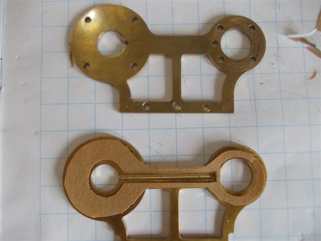
                I took the cylinder holders (frames) apart today intending to make a paper gasket for this part of the engine. It is a good thing that I never soldered all this together as per the instructions …what a mess that would have been !

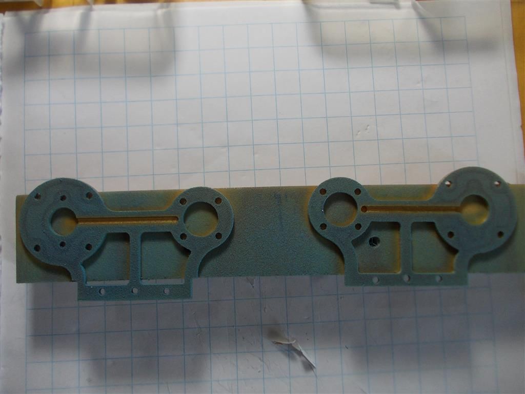
                My first observation was that there was a lot of oil spread over the inside of both frames indicating air leaks in this area. My attempts at cutting a paper gasket were a complete disaster so I decided to try the Hylomar again. This time I laid some plastic tubing on the connecting groove to mask it off before spraying. All seemed to go well and I slowly put everything back together eventually achieving the same degree of freewheeling as I had before.

                It still does not work !

                1. Bengs should supply a precut gasket for the frames. This is a very important part of the setup and mucking around with various compounds, never knowing if it has worked or not as just not good enough.

                2. I could try cutting five paper gaskets for the cylinder covers and where the cylinders contact the frames but I am starting to feel that I am wasting my time.

                3. New bearings will not solve my problem. I spun the flywheel once both pistons had been disconnected and I was getting somewhere between 30 and 40 revolutions ; I doubt that I could do much better than this. What are other people getting ?

                4. I have failed ''Gasket Cutting 101'' ! 

                5. Can Hylomar be used immediately or should I have waited 24 hours ? It does not say on the tin ?

                gasket 1.jpg


                gasket 2.jpg


                Edited By Brian John on 22/02/2016 07:12:13

                Edited By Brian John on 22/02/2016 07:13:07

                Edited By Brian John on 22/02/2016 07:14:12

                Edited By Brian John on 22/02/2016 07:14:37

                Edited By Brian John on 22/02/2016 07:15:31

                #226407
                Howi
                Participant
                  @howi

                  Brian you seem to be blaming Bengs again, YOU chose to deviate from Bengs instructions, you cannot now say it is their fault.

                  Making changes/not following instructions without the necessary experience/knowledge has led us to where we are.

                  My suggestion at this point would be to assemble everything as it should be.

                  Disconnect the work piston from the flywheel

                  Provide heat to the end of the glass displacer cylinder ( wait for 60 seconds at least to get some heat in) then slowly turn the flywheel over which should move the displacer piston as you turn the flywheel you should see the work piston moving in and out due to the action of the displacer. IF this does not happen then something is wrong somewhere. Either air not getting through or air leeks.

                  #226410
                  pgk pgk
                  Participant
                    @pgkpgk17461

                    Is there supposed to be an obstruction left in the end of milled groove between the 2 cylinder supports?

                    #226417
                    Brian John
                    Participant
                      @brianjohn93961

                      Howi : NOBODY on this forum has got this engine to run yet so it cannot be just my deviations that are to blame. The point I was making is that the seal between the cylinder holders is VERY important. It should not be left to chance using liquid sealers of any type, particularly since the instructions call for these parts to be then soldered in to the base plate. Where would I be had I followed those instructions ? I would have to de-solder and resolder every time the engine had to be disassembled.

                      pgk : do you mean on the D. piston side ?

                      Edited By Brian John on 22/02/2016 09:43:10

                      #226427
                      roy entwistle
                      Participant
                        @royentwistle24699

                        I am inclined to agree with Howi This engine has been sold as Drawings Instructions and materials If these instructions had been strictly adhered to particularly the drawings and the supplied materials I feel that this engine would have had a reasonable chance of running

                        #226433
                        JasonB
                        Moderator
                          @jasonb

                          Well I've just watched about 8 of these engines on youtube and all look to be soldered, you can even see the solder on some so looks like at least 8 people got them to run by following the instructions.

                          Looks to me like the front plate is soldered on but the rear can be removed should the need arrise so no need to unsolder

                          J

                          #226436
                          pgk pgk
                          Participant
                            @pgkpgk17461
                            Posted by Brian John on 22/02/2016 09:42:36:

                            ……………………..

                            pgk : do you mean on the D. piston side ?

                            …….

                            Whatever side that is .. the larger aperture/smaller diameter support side. I was wondering how the air(pressure) is supposed to route between those cylinders

                            #226439
                            Andy Holdaway
                            Participant
                              @andyholdaway

                              Just for info, I have made this engine EXACTLY to the plans, and not got it to run. I don't think there is anything wrong with the design, but my tolerances may not be up to spec, although they're as good as I can get them.

                              The problem appears to be friction/ misalignment on the displacement cylinder connecting rods with my engine. I'll remake various bits when I have time.

                              #226442
                              Ajohnw
                              Participant
                                @ajohnw51620

                                Hylomar state let the solvent evaporate. When I've used it on cars that has happened by the time I get it on.

                                They do 3 grades. I assume light is the thinnest one. It can be brushed onto metal surfaces but the solvent evaporates pretty quickly in my experience.

                                A more watery semi setting variety maybe easier and better to use. Red Hermatite is one brand. A very thin coat which ever is used. These products are gasket lubricants not substitutes for them really. Red Hermatite less so.

                                Now the obvious things have been ruled out other than maybe distortion when it's bolted down I suspect you need to remake one or two parts. All those pillars aren't a good idea. Most likely the displacer con rod bearing and con rod and maybe the power piston after honing it's bore. The bearing will need an accurately set tailstock. One of the problems with making holes on a lathe is the fact that things tend to produce larger holes than their diameter so do try it on some scrap first. Tailstock misalignment generally makes the hole even bigger.

                                John

                                #226444
                                pgk pgk
                                Participant
                                  @pgkpgk17461

                                  Could i just ask the technical question of how those two frame parts would be soft soldered together? I'm guessing fluxed and then thin solder wire placed around the edge/inned circle of the cylinder supports between the two halves; then heat and allow to flow. or would it be better to place some thin spacer between the two fluxed halves for caplllary flow and apply solder all around once hot? Or tin both parts, place together and reflow?

                                  Jason, I only see two components of that main frame..once soldered access to the cylinder spaces is via the covers. the only way to clear solder blockage into the channel would be via a new drill hole from one side that you plug after or poking bits of bent wire in via cylinder support.

                                  #226446
                                  Andy Holdaway
                                  Participant
                                    @andyholdaway

                                    The two plates are not soldered together. The rear plate is soldered to the base, and the front plate is then bolted to the rear by means of the cylinder bolts and a single 2mm bolt at the bottom.

                                    #226447
                                    Brian John
                                    Participant
                                      @brianjohn93961

                                      PGK : larger aperture is the work piston. There is a hole in the end of the frame which connects to a hole which has been drilled down the side of the cylinder. This hole exits at the top and so connects the two cylinders. I am not sure if that is clear ?

                                      Tomorrow I will make paper gaskets for all cylinder covers. If that does not work then I will try an aluminium flywheel. I may also make another work piston/cylinder assembly but this will not be ''drop through''. I will keep as much compression as I can this time.

                                      I am not sure why soldering as per the instructions is any better than bolting the cylinder holders to the base ? True, my engine does not work but I cannot see this as the cause. The only other modification I have made is to make the work piston rod adjustable by cutting a thread on the end and installing two lock nuts. The original design called for this to be soldered to the connecting rod joint which would not have allowed any adjustment to the length. Again, why should this cause any problems ?

                                      I also used a small nut and bolt for the working piston joint instead of a rivet.

                                      NOTE from the instructions : '' After deburring, cleaning, and adapting the parts the base plate can be soldered softly.'' It does not really specify what is to be soldered.

                                      Edited By Brian John on 22/02/2016 12:08:46

                                      Edited By Brian John on 22/02/2016 12:14:05

                                      Edited By Brian John on 22/02/2016 12:15:19

                                      Edited By Brian John on 22/02/2016 12:18:03

                                      #226450
                                      pgk pgk
                                      Participant
                                        @pgkpgk17461

                                        OK.. I didn;t see that hole before you pointed it out.

                                        On jan ridders engine he recommends silicone for sealing .. simple clear builders silicone applied in a tiny amount to covers. I haven't tested for leaks as such but whenever i take the bits apart there's a nicely squashed very very thin even layer of the stuff there (which peels off easily). A lot easier than making sets of gaskets..any diy or builders merchants.

                                        #226451
                                        Brian John
                                        Participant
                                          @brianjohn93961

                                          Something like this ?

                                          **LINK**

                                          The instructions mention ''sanitary silicone'' : How does that differ from other silicone sealants ?

                                          https://www.masters.com.au/product/900004549/fuller-770-sanitary-silicone-sealant-300g-mid-grey


                                          Edited By Brian John on 22/02/2016 12:31:03

                                          Edited By Brian John on 22/02/2016 12:31:25

                                          #226457
                                          pgk pgk
                                          Participant
                                            @pgkpgk17461

                                            have no idea of the diffrence between builders silicone and sanitary silicone.. I just used the ordinary cheap clear builders silicone comes in those cartridges you pop into an applicator and seal around windows, brickwork, fish tanks etc'. It does coem in a few colours but that shows up my incompetence more

                                            #226458
                                            JasonB
                                            Moderator
                                              @jasonb

                                              PDK as I see it only one plate is soldered to the base, the other plate (cylinder side) is sealed to the first with silicon.

                                              But if I were soldering two plates like that together I would tin both of them that means apply a thin coat of solder to each, then hold them together and reheat which is known as sweating and then melts the two coatings of solder into one.

                                              I use a silicon type liquid gasket on teh IC and steam engines, as you say just a smear is all that is needed.

                                              Sanitary silicon has antoi bacterial additives to help stop mould and mildew

                                              #226459
                                              JasonB
                                              Moderator
                                                @jasonb

                                                If you look at this one you can see the fillet of solder along the bottom of the flywheel side plate where it joins the base and also the two reinforcing webs. there is no sign of solder on the other plate and the central bottom screw helps hold the two plates together.

                                                The photos here also show very clearly that one plate is fixed to the base the other just held by the various screws and sealant.

                                                You may also want to translate the guys third post where he talks about the wooden base causing distortion, John touched on this a while ago.


                                                Edited By JasonB on 22/02/2016 13:45:02

                                                #226460
                                                Brian John
                                                Participant
                                                  @brianjohn93961

                                                  Well, his machine goes like the clappers…much faster than the first video we were shown. One thing I noticed immediately was that he has eight bolts on both D. and work front cylinder covers and not the four as per the instructions. I wonder if that was done for a reason…was he having leakage at those points ?

                                                  He has also made his support columns from brass and not aluminium. You might remember that I was having trouble machining the aluminium and I did consider switching to brass at one point. I think it looks better too.

                                                  I have looked around the internet and settled on this silicone gasket material from Autobarn :

                                                  **LINK**

                                                  I will try this instead of paper gaskets.


                                                  Edited By Brian John on 22/02/2016 13:47:19

                                                  #226461
                                                  pgk pgk
                                                  Participant
                                                    @pgkpgk17461

                                                    Thasnks, jason. Sweating was the word i;d forgotten (hence reflow0..

                                                    #226465
                                                    Ajohnw
                                                    Participant
                                                      @ajohnw51620

                                                      The acetic acid these silicones give of will do something to brass – that's what was suggested for cleaning the hob burners on a stove we had. It works too even at vinegar concentrations. Probably doesn't matter but if it gets too hot it reverts – to sand. The other question about them is what filler has been used. There is a clear type intended for adhesive type use = more vinegar smell. Often used for making aquariums.

                                                      To be honest with these engines especially at lower power levels unless people think about maintaining alignment when parts are made other similar factors there are likely to be problems. Also I suspect some honing will be needed in the power piston area. Not a problem really but info on making hone seems to be far more complicated than it needs to be. There is a Stirling Engine model engineers type book about that shows a simple hone. I bought it years ago but in useful terms there isn't much else in it. The suggestion for finishing the piston is very fine sand paper of a width greater than the piston but there are better materials available these days.

                                                      I could post a photo of the hone but the copyright owners might object. They might be the people that run this site.

                                                      There is rather a lot about NOT finishing it and applying heat immediately.

                                                      John

                                                    Viewing 25 posts - 476 through 500 (of 764 total)
                                                    • Please log in to reply to this topic. Registering is free and easy using the links on the menu at the top of this page.

                                                    Advert

                                                    Latest Replies

                                                    Home Forums Stationary engines Topics

                                                    Viewing 25 topics - 1 through 25 (of 25 total)
                                                    Viewing 25 topics - 1 through 25 (of 25 total)

                                                    View full reply list.

                                                    Advert

                                                    Newsletter Sign-up