Stirling Engine : Laura

Advert

Stirling Engine : Laura

Home Forums Stationary engines Stirling Engine : Laura

Viewing 25 posts - 426 through 450 (of 764 total)
  • Author
    Posts
  • #225475
    Brian John
    Participant
      @brianjohn93961

      I just performed an interesting experiment : removed D. piston connections to the crank but left D. piston in place at BDC with glass tube over it in the usual operating position. Turning the flywheel by hand, the work piston forced enough air through the system to gradually move the D. piston up to the end of the tube by about 2mm per revolution. So I think all the airways are clear and operating as intended.

      I am almost finished the single rod/clevis conversion so I will try that first. I am curious to see if it makes any difference. If I have no luck there then I will return to the initial design.

      Advert
      #225569
      Brian John
      Participant
        @brianjohn93961

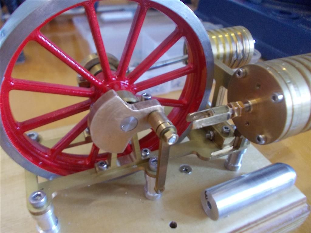
        I stuffed up my first attempt at the clevis : the M3 thread was not cut square when I tapped it by hand in the vice so I had to make second one. This one was tapped using the lathe to keep it square which was a success. I then redrilled the first clevis to 2.6mm ( correct tap drill is 2.5mm) and retapped it in the lathe with the plug tap and this worked. The thread is now square so I have two clevis. (What is the plural of clevis…clevii ?)

        I will assembly it tomorrow and work out the correct length for the D. piston connecting rod. I put an M3 thread on the connecting rod today using the lathe and made the thread long enough to take two adjustment nuts.

        Almost there !

        assembly 11.jpg

        Edited By Brian John on 16/02/2016 06:46:41

        #225612
        Howi
        Participant
          @howi
          Posted by Brian John on 15/02/2016 13:47:20:

          I just performed an interesting experiment : removed D. piston connections to the crank but left D. piston in place at BDC with glass tube over it in the usual operating position. Turning the flywheel by hand, the work piston forced enough air through the system to gradually move the D. piston up to the end of the tube by about 2mm per revolution. So I think all the airways are clear and operating as intended.

          If that is the case there is something seriously wrong somewhere. There should be a sufficiently large gap around the D piston to allow air to flow freely around it. Air being forced back towards the D piston should flow round it NOT push it up the glass cylinder. The D piston ONLY moves air within the glass cylinder, it does NOT provide any means of supplying force to the power piston, that force is supplied by the increase and decrease in pressure of the air in the system due to repeated heating and cooling of the air by the action of the D piston( Boyles law)


          #225615
          Ian S C
          Participant
            @iansc

            I can see one major problem with that last set up, the pivot point is too close to the crank to fit a working con rod, the pivot point has o be the same as the original.

            You mentioned how the displacer move when it was disconnected, and the piston was moved. This is the basis of the Ringbom motor, in this motor the displacer is not connected to the crankshaft, the only thing that is different is that the displacer rod is quite a bit larger, up to about 1/3 the bore of the displacer cylinder, I'v built three of this type, not over powerful, but they will run in either direction.

            Ian S C

            #225624
            Brian John
            Participant
              @brianjohn93961

              Howi : that experiment was with the largest diameter piston (12.9mm). I have made three of various diameters. The correct diameter is 12.5mm. It was only an experiment to test for air leaks. I am sorry that I did not explain that better.

              Ian : Yes, I see what you mean. I am using the same connecting rod from the original design. The clevis is too long and there is no room to fit a shorter one.

              I think I will have to remake part 24 (D.cylinder cover). I really think this is the main problem. I have run out of other ideas !

              #225637
              Ajohnw
              Participant
                @ajohnw51620

                Your problems might just be a bit of binding due to things not lining up Brian. That sort of thing showed up when you ordered new ball races. For those to work as they should the pockets they fit into need to be perfectly axially aligned and square to each other. Same with the con rods. In that case the holes in each end need to be on the same axis, same distance apart when there is 2 on the same journal and their sides need to be square to the holes too. This sort of thing is why asked if your drill table was square to the drill earlier. Few are worse luck. Usually it's possible to square them up one way and the other may need some thought as to how the work is set in a vice and it can be impossible to do that. If this is one of the problems the easiest solution would be to easy the holes a bit and if possible ensure that the holes in the 2 are the same diameter and the same distance apart.

                This sort of problem has cropped up in some model engineer mag projects in the past and if extreme they have suggested drilling in the lathe. There are 3 ways of doing that. One is holding them on the face plate but that needs the face plate balancing. That's not too bad on small light things as one clamp will hold the work and another can be fitted just to balance things. The other is a drilling plate in the tailstock. I've been looking for one for years. All that can be bought is cross drilling jigs and they are too small to hold things down on. They aren't much good for cross drilling either really, no clamp and the V is usually too small. The other way is some sort of holder in the tool post. It can be fly cut from the chuck to get it square on. I have done this at times using a lash up to allow me to jig bore pretty accurately using the cross slide.

                The other aspect which you probably have thought of is to make matching parts in one go. Take the double con rod. Drill ream one end of each, fit a tight fitting dowel and then do the other ends together. If these are the problem you might cure it by simply relieving the holes a bit.

                If I used any oil on these things I would get hold of some watch or clock oil but it can't be used on any really hot bits.

                That long hole on the displacer shaft is a good idea. The way to view the length of holes like this is how many diameters of the shaft they carry long are they. More diameters means less tip for the same amount of clearance. If say they are 1 dia long rather than say 3 there will be something more akin to point contact at each end of the hole which in practice is likely to cause more friction in a case like this. Too much clearance will have a similar effect.

                John

                #225641
                Brian John
                Participant
                  @brianjohn93961

                  I have reassembled the engine as per the original design but with only ONE con rod (the outside one). If I can get this to work with one con rod then I will add the other con rod later. But there is friction there somewhere even with only one con rod. It is late at night now so I will be having a close look at everything tomorrow.

                  #225750
                  Brian John
                  Participant
                    @brianjohn93961

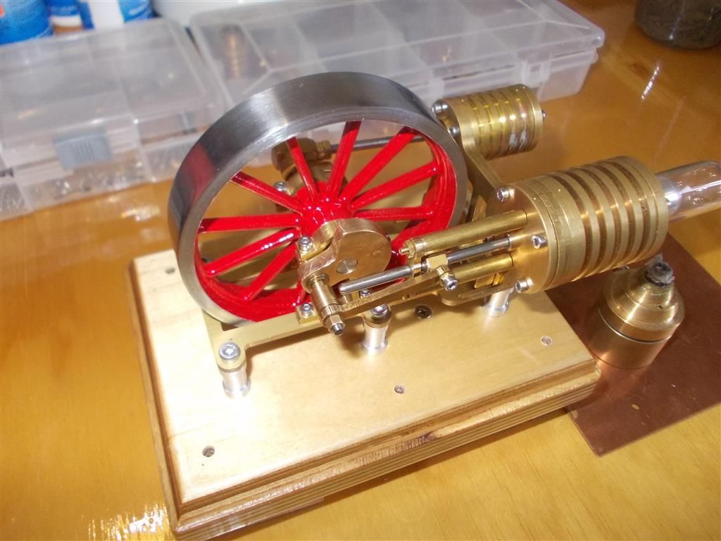
                    Very frustrating : I have pulled everything apart, polished many parts with 2000 grit wet and dry and then reassembled the engine with only one con rod. I have oiled all moving parts despite the advice to the contrary as I am running out of options. I am not happy with the supplied bearings but the replacements bearings have not arrived from Hong Kong yet so I will have to stick with what I have.

                    Things are running much better now. I am getting  8 revolutions when spinning it by hand with everything connected (one con rod on the D Piston). When the burner is applied I am getting about 16 revolutions. I am sure it is not my imagination It really wants to run but something is stopping it. Possible solutions are :

                    1. It is very hot here today, especially inside the house (about 40 degrees C). The work cylinder gets hot very quickly ; there cannot be too much of a temperature difference between the two cylinders. I might try again later tonight when the air con is on.

                    2. The supplied bearings are not up to scratch. You might remember that I have put shims between the bearing supports and the covers to stop the bearings being crushed out of shape. It could be that before I inserted the shims that I damaged these bearings when tightening things up the first time. Nothing to do here but wait for the new ones to arrive.

                    assembly 12.jpg


                    Edited By Brian John on 17/02/2016 06:58:05

                    Edited By Brian John on 17/02/2016 07:00:42

                    Edited By Brian John on 17/02/2016 07:10:33

                    #225751
                    pgk pgk
                    Participant
                      @pgkpgk17461

                      Apply soapy water to all the junctions? Seal leaks with silicone.

                      If you have a dremel type tool then use the rubber mandrel in the kit agaist the flywheel to spin it up for a while?

                      Ice the cold side?

                      Pull the bearng shields off and flush out the grease, leave open?

                      Sounds like you're close.

                      Edited By pgk pgk on 17/02/2016 07:14:54

                      #225757
                      Danny M2Z
                      Participant
                        @dannym2z

                        Brian, you shall get it running eventually.

                        Lol, 432 Posts and 28,192 views – the whole world is waiting with bated breath.

                        Now you are at the stage of eliminating the niggles by focusing on the details

                        I reckon that you have learned heaps about your lathe (which was your aim) so quite a worthwhile exercise.

                        There will be applause all round when the little machine runs on it's own and once you have built one, the next one should become easier. I suspect that they could become quite addictive (Ian SC in NZ seems to be quite fond of the little beasties).

                        Party time in Cairns is close!

                        Regards * Danny M *

                        #225759
                        Brian John
                        Participant
                          @brianjohn93961

                          Perhaps a cork gasket between the work cylinder and the cylinder holders (frames) ? This might stop a lot of the heat being transferred from the D cylinder to the work cylinder. We will see what happens tonight after the air con has been running for a few hours.

                          A gasket  on the D cylinder would also minimise heat transfer to the other side. There are still many things to try yet.

                          Edited By Brian John on 17/02/2016 08:46:28

                          Edited By Brian John on 17/02/2016 08:47:14

                          #225778
                          Ajohnw
                          Participant
                            @ajohnw51620

                            I was laying on a bit thick with the alignment of things Brian. It all comes down to clearance between them to some extent but there will be limits on that too. The alignment needs to be better than the clearance otherwise there wont be any.

                            The problem with ball races is that they have virtually no clearance between the running parts. The size of the hole this sort of size goes in is likely to need to be correct to very few 1/10 thou and also round to an even tighter tolerance. Your best bet may have been to bore or ream them together with the caps on and us a tiny speck of super glue in each half. Or nyloc type retaining fluid.

                            Not sure where you are putting the flame. I'd suggest small and not too far from the end. The power cylinder shouldn't be getting too hot to touch. The other aspect is adjustment. As I'm thinking of making one looking around suggest the displacer at it max stroke should go right down the tube to a point where the end clearance is more or less the same as the clearance around it's side. If the clearance is too small it wont work. The power cylinder isn't so simple. That seems relates to the compression ratio of the engine and the ones I have been looking at are all low temperature so that is extremely low. In your case you can probably vary it by say starting with the piston reaching the end of it's cylinder and the reducing the ratio by moving it back. Further back will reduce the compression ratio which in turn "should" reduce the temperature differential needed for it to run. I doubt if that aspect is as precise as the academics reckon but generally it seems to be correct.

                            Leaks seem to be bad news too and the pressure goes up when the things are heated. Adding a bit on that. The engine is likely to run a bit roughly until that settles down.

                            It looks like there are 3 pedestals on each side of the brass plate. Try just using the outer 2 on one side and the central one on the other. 3 point suspension shouldn't distort the plate. The way to make equal length pedestals is with a back stop in the spindle to finalise the length or by using the compound slide for sizing. Face the end with a parting tool and then cut to length. Or the saddle feed if the lathe has one as per myford.

                            John

                            Edited By Ajohnw on 17/02/2016 10:24:01

                            Edited By Ajohnw on 17/02/2016 10:25:21

                            #225783
                            Ian S C
                            Participant
                              @iansc

                              John, Loctite (nyloc, type of self locking nut), retaining fluid, screw / nut lock

                              Brian on my first motor I found that I had to loosen the nuts holding the caps on the bearings to get them to run properly. I for got about the front bearing on the displacer rod, I wonder about that, is it dead in line? I would hope it's not too tight. It's a idea I have thought of, but never used (yet).

                              On hot air engines compression ratios are not looked at the same as an IC motor, if the power piston stops at .5 mm from the head, or 5 mm from the head, it will make very little difference in the running of the motor, so the main thing is, it will work as long as the piston doesn't hit the end.

                              Ian S C

                              #225785
                              Brian John
                              Participant
                                @brianjohn93961

                                Thanks Ian : I will not worry about adjusting the work piston then. It would be a waste of time. I have been thinking of making some brass bushes (10mm OD, 6mm ID) to use instead of the ball bearings. My gut feeling is that the bearings are the problem. While I think about that I will try some slightly larger diameter and slightly small diameter D. pistons. I already have them made up so I may as well try them…nothing else is working.

                                NOTE : the air con did not help !


                                Edited By Brian John on 17/02/2016 11:22:10

                                #225787
                                Howi
                                Participant
                                  @howi

                                  Brian as has been said, the power cylinder should NOT be getting hot. All that finned brass should be able to dissipate the small heat transfer from the air in the displacer. This needs investigating. Keep the heat applied to the very end of the glass tube, as it is borosilcate it will not transfer much heat through itself to the brass parts. These look to be quite substantial items so should not even feel warm let alone hot.

                                  #225788
                                  Ajohnw
                                  Participant
                                    @ajohnw51620

                                    The compression ratio of a stirling engine Ian is the ratio of the enclosed volume with the power piston at each end of it's stroke. And yes it does matter but pass on how much.

                                    Actually – it matter rather a lot on the very low temperature differential types.

                                    John

                                    Edited By Ajohnw on 17/02/2016 12:00:13

                                    #225789
                                    Brian John
                                    Participant
                                      @brianjohn93961

                                      I think the air con may be making a difference as the power cylinder is not getting hot now. It was 40 degrees inside the house today ! I have tried a 12.4mm D. piston instead of the recommended 12.5mm piston and I am getting the engine up to about 24 revolutions…..so close ! I am using lots of oil on all moving parts.

                                      I wonder if I should adjust the work piston ? The original plans called for the piston rod to be soldered to the connecting rod joint and no adjustment could be made that way but I have made it adjustable by cutting a thread on the end. I think soldering parts on an engine like this is a pretty silly idea !

                                      Edited By Brian John on 17/02/2016 12:01:33

                                      Edited By Brian John on 17/02/2016 12:06:06

                                      #225791
                                      Howi
                                      Participant
                                        @howi

                                        Hi Brian, sounds as you are nearly there, try adding more heat from say a blowlamp, your burner may not be giving it the heat it needs to sustain continual rotation.

                                        #225792
                                        Brian John
                                        Participant
                                          @brianjohn93961

                                          I am a bit reluctant to do that at this point as it should not be necessary. But I will give it some thought. I would like to try the new bearings first.

                                          I have set the work piston so that it is as close as possible to the cylinder head without actually touching. What is the correct setting for a work piston on a Stirling engine ?

                                          Edited By Brian John on 17/02/2016 12:44:43

                                          #225804
                                          Ajohnw
                                          Participant
                                            @ajohnw51620

                                            Having looked around Brian Stirling Engine design is a bit like black magic / suck it and see. If the power piston is fixed I'd just check it's to drawing and look for other problems. One aspect that will be important is the fit. Drop through but not when a fingers is over the other end. That needs a very high surface finish and a close fit – more like an air bearing than anything else. The phasing of the two "pistons" should be 90 degrees. They all seem to be apart from some academic research which is still close to that. Many types also only run in one direction. I'd guess that the direction of the phasing sets that.

                                            You could fix a block of ice from the freezer to the power cylinder some how but I doubt if that is your problem if it's a small flame near the end of the test tube. The displacer getting too hot along it's length may mess things up.

                                            On the flywheel bearings I'd expect the flywheel to spin for a very very long time spun up on it's own. Many minutes. I'm a bit at odds with no lubrication in them but going on some styles of beach casting reels it needs to be a very light oil and very very little of it. On the reels people wash them out in lighter fuel then add the oil but they are after a pretty precise level of braking. The stuff that comes in the bearings is no good for that. They also free up considerably after several casts. They run at very very high rpm for some of a cast. They could be "run in" on a lathe.

                                            I'm still inclined to feel you should drive it from your lathe for a while. Say an elastic band round the flywheel and a bit of bar come pulley in the chuck to get I don't know say 100 rpm or so.

                                            John

                                            #225812
                                            Brian John
                                            Participant
                                              @brianjohn93961

                                              The power piston is a good fit (drop through) and highly polished. I spent a lot of time getting that side correct so that I would not have to worry about it later.

                                              I am 99% certain that the problem is the bearings. They never did seem very free running to start with. I was quite surprised. Perhaps I should have washed them out and re-oiled them before assembly. I may still do that tomorrow : kerosene or methylated spirits…I have no lighter fluid on hand ?

                                              NOTE : the new bearings were posted from HK on the 2nd February so could arrive at any time. I would expect next week but who can tell when you live in Cairns…it be 10 days from Sydney !

                                              Edited By Brian John on 17/02/2016 14:42:50

                                              #225825
                                              Ajohnw
                                              Participant
                                                @ajohnw51620

                                                Lighter fuel is still pretty easy to get in the UK. We have £ / everything should be cheap shops. Main problem with it is getting rid of it after use. Best way is a very small dish of some sort as not much is needed and then setting it alight. There may be a bit of a bang come pop when the fumes ignite. Unleaded should do just as well. Small bottle of that may be available from fishing tackle shops for Colman pressure lamps. Meths should do some like acetone.

                                                You could run the bearings up on your lathe. Turn something to hold them via the centre only. Run the lathe flat out and stop the outer from rotating. I'd use my finger being me but a pencil or bit of wood etc should be fine. Another way with an air line and bearings that are open is to hold the centre and blow at an angle onto the balls. Apprentices and others then drop them and they fly for amazing distances if they land on their edge.

                                                I've been looking at run on the hand types. One mentions that when the flywheel is flicked round firmly on it's own it should run for several minutes. A very light flywheel. It use 2 683 stainless steel degreased and demagnetised bearings. 3mm bore, 7 odd and 2 thick. They show shields on one side in one somewhere. If the bearings have metal shields on both sides I've managed to get one out and put it back in the past, usually with care and a pin.

                                                I found a good description of relubing a 7HT but they are after creating a certain amount of drag. Interesting way of getting oil in though.

                                                wink http://hwee_surfcast.tripod.com/LubricatingBearings.htm

                                                I've seen some designs where the bearings are held in recesses in each end of a short piece of bar. I'd hope that people would make and use a mandrel to locate things before forming the recess on both ends rather than just reverse in the 3 jaw. I think that as the bearings are usually a light press fit I'd machine straight through and use a spacer.

                                                John


                                                Edited By Ajohnw on 17/02/2016 16:13:27

                                                #225828
                                                Gordon W
                                                Participant
                                                  @gordonw

                                                  I don't like to be a nanny, but have mentioned this before– Do not stick a finger in a bearing and blow with an air-line. Seen it done many a time and once saw it seize up. Bearing and finger went quite a long way.

                                                  #225832
                                                  Ajohnw
                                                  Participant
                                                    @ajohnw51620

                                                    Of course sticking a finger in the hole in the centre of a bearing would be a pretty stupid thing to do – that's why i said hold the centre.

                                                    John

                                                    #225837
                                                    pgk pgk
                                                    Participant
                                                      @pgkpgk17461

                                                      The lazy way to fush a bearing is with two cones…one with a hole down the centre that will fit on a syringe (canine nasal vaccine applicators are ideal) and the second cone to sit the bearing in ..often an eggcup will do. Force the flush solution down the centre and it has nowhere to go but past the shields, through the bearing and up.

                                                      It used to be suggested as a way of regreasing bearings but is daft for that.. no control over the grease amount and too much will bind them.

                                                    Viewing 25 posts - 426 through 450 (of 764 total)
                                                    • Please log in to reply to this topic. Registering is free and easy using the links on the menu at the top of this page.

                                                    Advert

                                                    Latest Replies

                                                    Home Forums Stationary engines Topics

                                                    Viewing 25 topics - 1 through 25 (of 25 total)
                                                    Viewing 25 topics - 1 through 25 (of 25 total)

                                                    View full reply list.

                                                    Advert

                                                    Newsletter Sign-up