Stirling Engine : Laura

Advert

Stirling Engine : Laura

Home Forums Stationary engines Stirling Engine : Laura

Viewing 25 posts - 401 through 425 (of 764 total)
  • Author
    Posts
  • #225124
    Brian John
    Participant
      @brianjohn93961

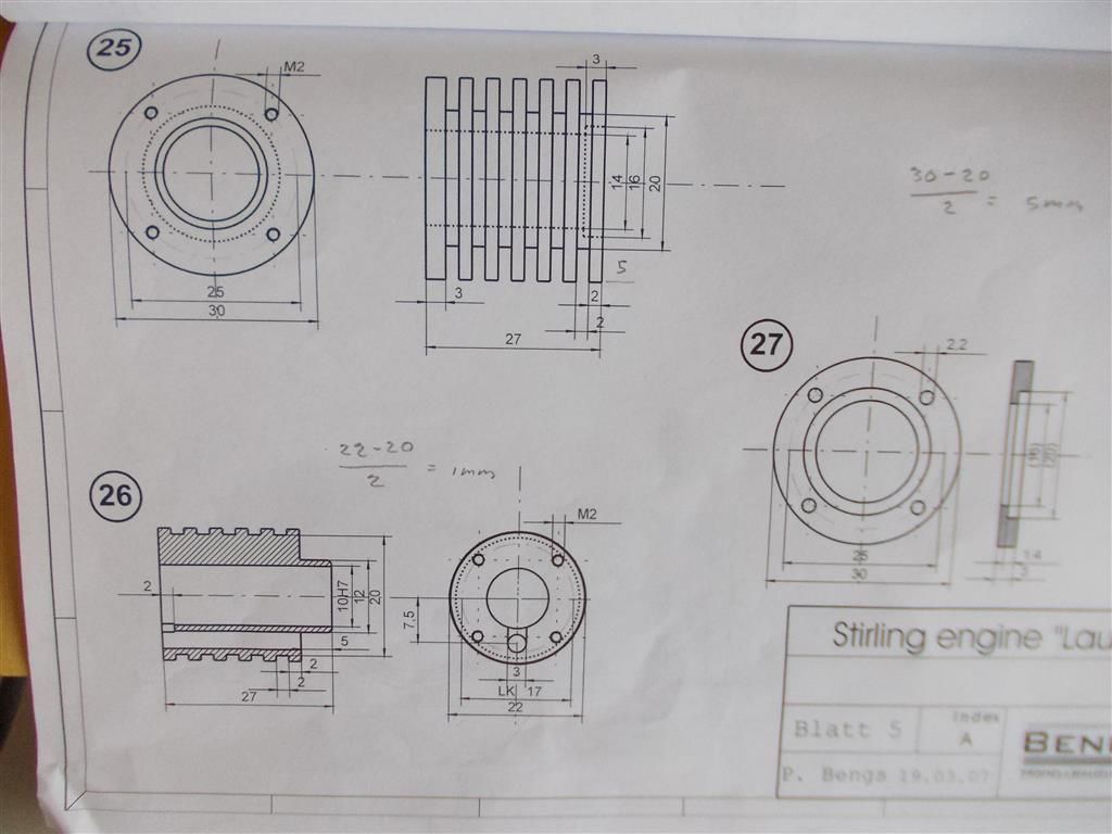
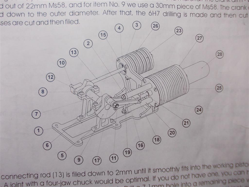
      I may have missed something here. Please have a look at the work cylinder plans and tell me what that ''2'' is to the left of the cylinder (part 26). Is that 3mm hole running down the side of the cylinder connected to the main bore of the cylinder at this point ?

      plans 3.jpg


      Edited By Brian John on 13/02/2016 08:13:02

      Edited By Brian John on 13/02/2016 08:13:26

      Advert
      #225130
      Howi
      Participant
        @howi

        The 3mm hole is connected to the cylinder bore at the top of the cylinder and is shown as 2mm deep. The air in the system has to move freely between the power piston and the displacer piston with no leaks. A way to check if everything is OK is to disconnect the power piston and displacer from the flywheel, apply heat as normal and manually move the displacer piston backwards and forwards, you should see the power piston moving in relation to the displacer.

        #225134
        Kettrinboy
        Participant
          @kettrinboy

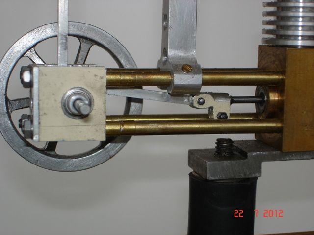
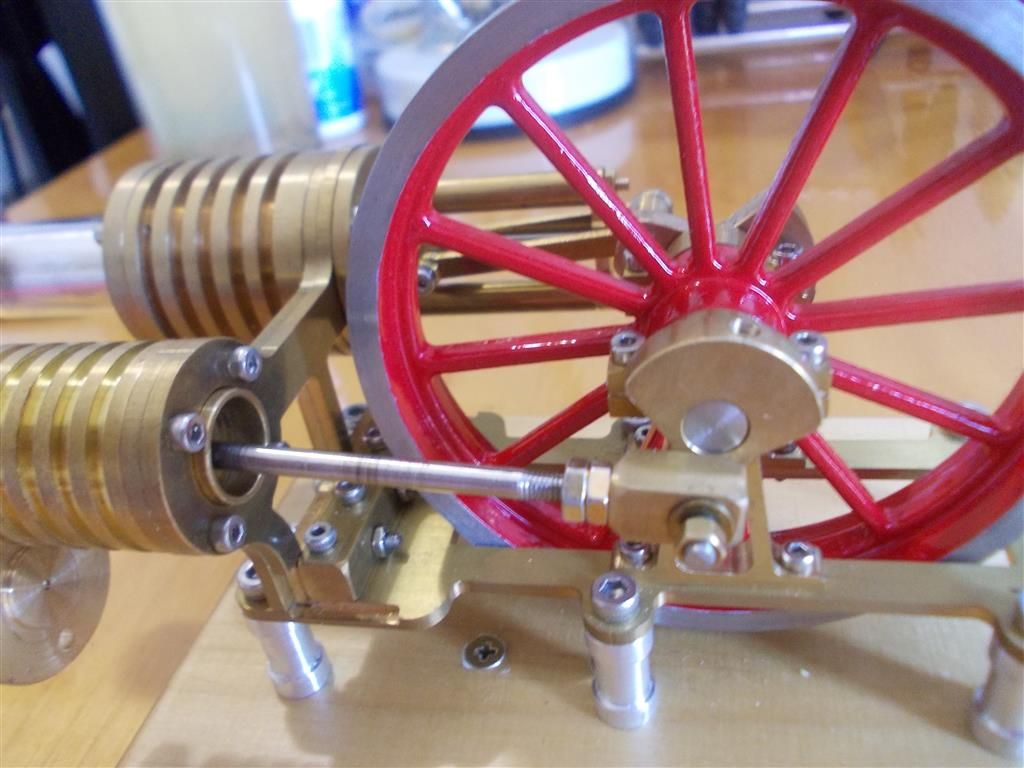
          linkage.jpgThe displacer piston drive linkage on that engine looks over complicated and would need pretty accurate machining for it to run freely , any linkage on a hot air engine needs a bit of play to account for tolerance buildups elsewhere and the design on this one doesnt seem to allow much if any hence the tight spots , if you cant get this one running freely i would be tempted to convert to a single rod running a clevis at the cylinder end for adjustment of the displacer piston , see pic of my similar type engine , it doest look fancy but its far easier to make and it works very well.

          regards Geoff

          #225149
          Ian S C
          Participant
            @iansc

            I agree with Geoff regarding the coupling to the displacer rod, as you have it on your motor it would tend to pull/push side ways, creating a friction area. The fork that I use fits on a plain rod, and is held by a pinch bolt, saves putting a thread on the rod (lazy). I even used that system on my smallest motor, 3/8" bore. Displacer rod 2.5 mm dia.

            Ian S C036 (640x480).jpg

            #225161
            Ajohnw
            Participant
              @ajohnw51620

              You could lap the sliding and pivot points away from the cylinders Brian but that passage / slot etc between the 2 cylinders is needed.

              An all purpose plastic/metal/work surface kitchen cream might be a bit coarse for lapping. Something like silvo or brasso mixed 50/50 with oil should be ok. The kitchen creams are great for lapping machine slides on new machines. Certain smokers tooth pastes, liquid in a dropper bottle spring to mind as well. or even tooth paste and oil.

              Some people use a drop of sewing machine oil on stirling engines in some areas. It's silicon oil though. I'm reminded of a massive vat of the stuff in a semiconductor factory and wonder how it managed to coat the walls of the room it was in. Later in became clear when Brit Telecom banned silicon products from exchanges that still used mechanical relay type things to route calls. The cleaners were using products that contained silicone oil to clean the floors and it was getting onto the contacts – sparks – heat and it reverts to silicone = sand. It seems the stuff creeps.

              surpriseTo lap I would hook it up to say my electric drill some how and run it for a while.

              John

              Edited By Ajohnw on 13/02/2016 11:29:35

              #225178
              Ian S C
              Participant
                @iansc

                James G. Rizzo* recommend that a time is spent running the motor in under power from another motor, or the lathe.

                * "The Stirling Engine Manual" volumes 1 and 2, and "Modelling Stirling and Hot Air Engines".

                Brian, if you disconnect the con rods, and give the crankshaft a good flick, it should rotate for a minute or so. With just the displacer connected, it should rotate for quite a number of turns. I have always built my motors on a ridged metal base which is then if required attached to a wooden base (don't trust the brown stuff). I have got a little Bohm HB7-A02 that I got from Jaycar, and it is mounted direct to the wood (it's got other problems too).

                Ian S C

                #225265
                Brian John
                Participant
                  @brianjohn93961

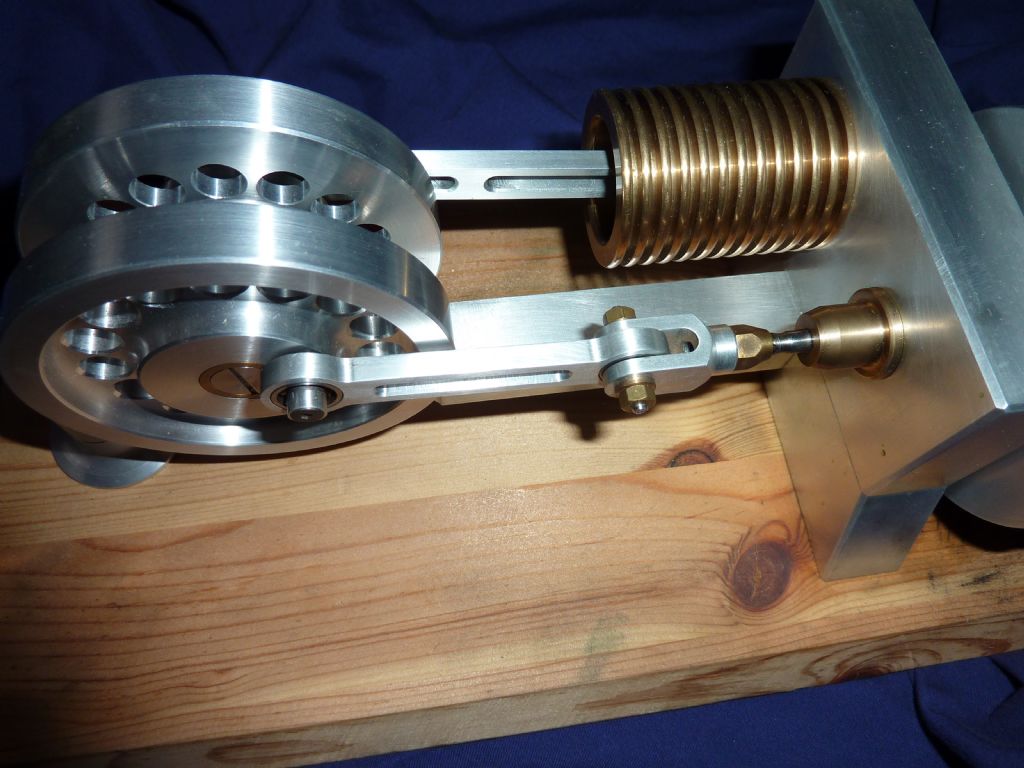
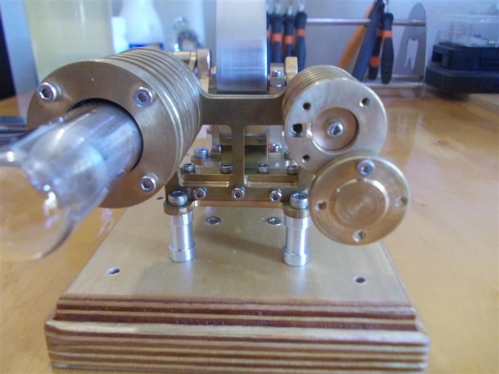
                  I used a 2mm drill bit in my bench drill as a milling machine to connect the hole to the main bore of the work cylinder. The engine runs much more freely now as the work piston is not just compressing air. When I spin it by hand it turns for about eight revolutions which I think is about as good as it gets. I like the improved linkage idea as outlined above and I will try that eventually but I do not think that friction is my problem now ; there is something else wrong and I am not sure what.

                  You can see the adjustment mechanism in photo #1 I made for the work piston connecting rod. This allows me to adjust the length and get the piston close to the cylinder head at TDC. Photo #2 shows the port outlet I made today and the piston at TDC…does this look about right ? I can't get it any closer to the cylinder head without it touching.

                  The work piston at TDC is just touching the newly enlarged port.

                  Very frustrating as it still will not run ! I get the feeling that it wants to. When heat is applied to the glass tube then the engine will turn over for about ten revolutions so something is happening. I tried to adjust the timing as I would a steam engine by advancing and delaying the crank slightly but this did not help….I did not really expect that it would but at this point I will try anything.

                  Points to consider :

                  1. The temperature here is very hot so maybe I cannot get a good temperature differential between the two cylinders ?

                  2. That hole down the side of the work cylinder may not be large enough or close enough to the bore to perform its required function ; I was worried about bursting through when I drilled it. As others have said, for a long hole like that it is best to just go straight to a 3mm drill bit rather than drilling pilot holes with smaller drills which will deflect. I may have to remake that cylinder again as it is not possible to enlarge that hole : the drill bit just wanders and follows the existing hole and would burst through the outer surface.

                  3. The heat transfers through the cylinder holders and the frame quite easily from the Displacement cylinder to the work cylinder. I assume that Bengs design does work and this is not the cause of my problem but what else could they have made the main frame and cylinder holders out of to reduce this heat transfer ?

                  4. I am tempted to make some gaskets for the cylinder covers as I would for a steam engine….a waste of time perhaps ?

                  5. What a bugger of a thing… it looks good though

                  assembly 9.jpg

                  assembly 10.jpg

                  Edited By Brian John on 14/02/2016 06:33:18

                  Edited By Brian John on 14/02/2016 06:38:54

                  Edited By Brian John on 14/02/2016 06:39:14

                  Edited By Brian John on 14/02/2016 06:40:02

                  Edited By Brian John on 14/02/2016 06:42:17

                  Edited By Brian John on 14/02/2016 06:44:12

                  Edited By Brian John on 14/02/2016 06:45:07

                  Edited By Brian John on 14/02/2016 06:45:40

                  #225271
                  JasonB
                  Moderator
                    @jasonb

                    Maybe the Sterling experets will correct me but now that Brian has connected that end of the work cylinder to the air passage down the side what happens at the other end? To my mind it will be blocked off when the cylinder is fixed to the support plates, if it is going to allow free passage of air then I would have thought there should be an opening at the support end.

                    Looking at Bengs site the photo towards the bottom showing the kit contents has a suitable hole in the mounting plate but the others don't?

                    Any thoughts

                    #225272
                    Brian John
                    Participant
                      @brianjohn93961

                      Jason : there is a hole connecting both cylinders. It runs along the inside of the cylinder holders once they are joined together. It was pre machined there. I do not think I have a photo. You cannot see it on the website.

                      #225284
                      Brian John
                      Participant
                        @brianjohn93961

                        I need to have a think !

                        Edited By Brian John on 14/02/2016 10:06:24

                        #225295
                        Ian S C
                        Participant
                          @iansc

                          Have you any leaks, the place I'm thinking of is the gland on the displacer chamber where the rod comes out, you could try with some soapy water to see if it blows bubbles, a slight leak will occur, but there should not be very much. All joints need to be air tight, ie the test tube into the metal body. It sounds as though you'v nailed the friction problem. The only other thing I can think of is the fit of the piston, if it's too loose, a drop of light grade oil on the piston will fill the gap, and then it may go. Some times just flicking it over is enough to settle it in, and after a while it goes, and usually as the motor gets run, it gets faster as it frees up.

                          Ian S C

                          #225299
                          Brian John
                          Participant
                            @brianjohn93961

                            Jason : you had me going there for a minute. I thought you had found the problem… but no ! Look at this diagram and you can see that the connecting groove of the cylinder holders (3 and 4) is sandwiched between the D.cylinder cover (24) and the D.cylinder (25).

                            Ian : I thought it was mentioned before that oil is a no-no in the pistons if Stirling engines ? I will try the soapy water on that gland to see if there is leakage there. If there is leakage at that point, is there someway to resolve the issue without making a whole new cylinder cover (24) ? If I knew how to thread cut on the lathe then I could make a gland cover and use some packing. Or perhaps I can do the same thing using an interference fit for the gland cover ?

                            I think part 24 is the only part I did not make two of…or three or four !

                            plans 4.jpg


                            Edited By Brian John on 14/02/2016 11:03:33

                            Edited By Brian John on 14/02/2016 11:04:27

                            Edited By Brian John on 14/02/2016 11:06:04

                            Edited By Brian John on 14/02/2016 11:23:24

                            Edited By Brian John on 14/02/2016 11:27:09

                            Edited By Brian John on 14/02/2016 11:32:02

                            #225328
                            Brian John
                            Participant
                              @brianjohn93961

                              UPDATE : I still have a friction problem. As an experiment I disconnected the crosspiece from the D.piston connecting rod : I gave the flywheel a spin and it ran for 30 revolutions compared to about 8 revolutions when fully connected. The problem is friction on the displacement piston side. I will sleep on this tonight to decide what to do next.

                              Edited By Brian John on 14/02/2016 12:57:45

                              #225362
                              Ajohnw
                              Participant
                                @ajohnw51620

                                I'd have to read back through a number of posts Brian but didn't you fit a bigger heavier flywheel?

                                I have a strong suspicion that would upset a Stirling engine as it need to accelerate it's mass on every stroke.

                                John

                                #225368
                                Brian John
                                Participant
                                  @brianjohn93961

                                  No, this is the original flywheel.

                                  I think I will make up a linkage with a single connecting rod and a clevis as per the photo posted by Kettrinboy above. At this point I do not see any other solution. All the friction has to be minimised and there are to many points of friction in the original design.


                                  Edited By Brian John on 14/02/2016 17:06:38

                                  #225423
                                  Hopper
                                  Participant
                                    @hopper

                                    Brianl have you checked that the displacer piston is not rubbing on the glass tube or the brass parts that hold it? That is a common source of friction in Stirlings.

                                    +1 on Ian SC's suggestion to run the engine in under power of an electric motor of some sort for an hour or so.

                                    #225426
                                    Brian John
                                    Participant
                                      @brianjohn93961

                                      I removed the glass tube and this did not make any difference to the friction so the glass tube is not the source of the problem.

                                      I am in the process of making a clevis pin and using a single connecting rod as per the above suggestion : it should be finished tomorrow. Hopefully, this will remove a lot of the friction.

                                      I am not sure why Bengs didn't go this way in the first place as it is much simpler to make ?

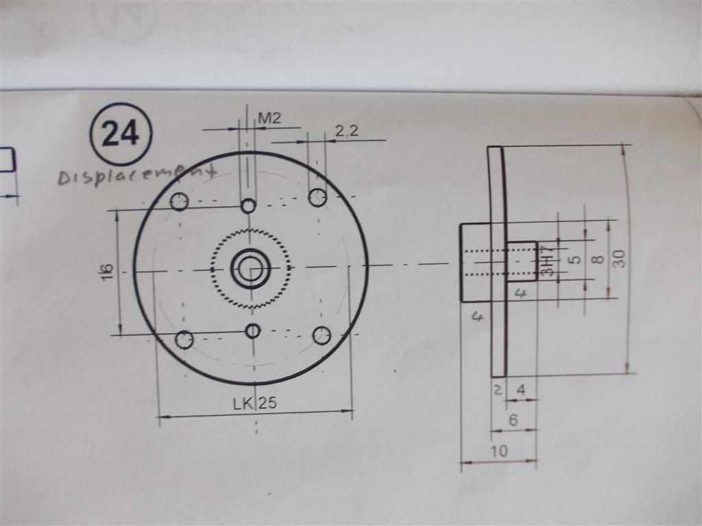
                                      I am still unsure about the D. cylinder cover (part 24). I do not understand why they have made the piston rod pass through so much brass (10mm in total) as this only adds to the friction.

                                      displacement cylinder cover plans.jpg

                                      Edited By Brian John on 15/02/2016 06:51:15

                                      Edited By Brian John on 15/02/2016 06:52:49

                                      Edited By Brian John on 15/02/2016 06:53:09

                                      #225433
                                      pgk pgk
                                      Participant
                                        @pgkpgk17461

                                        I think the idea is to use the thickness of brass as both steerage for the rod and a pinch point for the dsiplaced air. On the model i'm troubleshooting is a seperate bush – even longer and phos bronze into the ally cold cylinder.

                                        A carbon bush might be lower fricton, a cast iron one for duration?

                                        #225434
                                        Howi
                                        Participant
                                          @howi

                                          As you are getting 30 turns by spinning the flywheel, I would say friction is not your problem.

                                          It is more likely to be an air leak or no connectivity for the air between the displacer and the piston.

                                          If you remove the glass cylinder and the displacer, but leave the displacer rod in place, also disconnect the power piston from the flywheel, now blowing into the end where the glass cylinder goes, should push the power piston away from the flywheel, suck and it should go the other way.

                                          If you cannot get this to happen then that is your problem. You need to find where the blockage is. Once you get this sorted you should find it runs. 

                                          Check the plans and try and work out the air passages between the two cylinders and check you have done everything in this respect.

                                          This is a successful kit from Beings, trying to redesign it without the knowledge and experience will only lead to dissapointment.


                                          #225445
                                          Michael Gilligan
                                          Participant
                                            @michaelgilligan61133
                                            Posted by Howi on 15/02/2016 09:15:51:

                                            This is a successful kit from Beings, trying to redesign it without the knowledge and experience will only lead to dissapointment.

                                            .

                                            Wise words ^^^

                                            MichaelG.

                                            .

                                            Here is a nice example, running sweetly.

                                            #225449
                                            Brian John
                                            Participant
                                              @brianjohn93961

                                              Howi : I get 30 turns WITHOUT the D. piston being connected. When the D.piston is connected then I only get about 6 turns : this is the problem.

                                              The youtube link is interesting but I do wonder was it machined by hand or using a CNC lathe ? Remember, there are two other people building this engine at the same time as I and they cannot get their engines to work either.

                                              I may make another D.cylinder cover (part 24) .

                                              Edited By Brian John on 15/02/2016 10:52:11

                                              Edited By Brian John on 15/02/2016 10:52:43

                                              #225452
                                              Howi
                                              Participant
                                                @howi

                                                Brian, you need to approach testing methodically,  looking at the plans you have shown shows the air inlet to the power piston is at the end furthest from the flywheel, my previous post needs the action of the piston reversing in that case. The opposite end of the power cylinder needs an opening the the atmosphere otherwise you are wasting power compressing air, this air needs to go somewhere.. Another thing you could try is, remove the power cylinder end cover ( one furthest from the flywheel, then spin the flywheel. It looks a fairly hefty flywheel so kinetic energy should keep it turning more than 6 times. You could also disconnect the power piston Conrad and the displacer Conrad and push and pull by hand how do they feel, rough/smooth?

                                                Testing needs to be methodical and carefully worked out gradually adding more parts of the linkages until you have everything connected as it should be. The poke and hope method rarely works.

                                                Usually the blindingly obvious suddenly smacks you across the face with a wet fish. The "Ah! Bisto" moment.

                                                #225453
                                                Andy Holdaway
                                                Participant
                                                  @andyholdaway

                                                  Brian, I think you're probably on the right track with the rear cylinder cover. I have left my engine on the shelf for the past few weeks, but decided to have another go at it yesterday.

                                                  As Howi has suggested, I can blow and suck with abandon and move the power piston. However, I have some leakage around the displacement piston rod. This was reamed M3H7 and is pretty snug, but I still get air past it.

                                                  I'm sure my problems are down to machining tolerances (inaccuracies) caused by me, but the engine has served it's purpose in getting me used to my lathe.

                                                  There are a few videos on You tube showing running engines, so the design obviously works. One day I probably re-make all the key parts, hopefully more accurately, and try again. Until then it's an ornament!

                                                  Andy

                                                  #225463
                                                  Howi
                                                  Participant
                                                    @howi

                                                    Andrew, a little leakage is inevitable, a little drop of light oil should deal with that.

                                                    The next thing to consider is timing, get this wrong and you are on a hiding to nothing.

                                                    Turn the engine over by hand, with the displacer piston furthest away from the heat source, the heat is being applied to the greatest volume of air which is going to increase the air pressure ( as the volume is fixed) and so push the piston towards the flywheel ( power push stroke) 

                                                    . keep turning the flywheel, the displacer piston should now go towards the hot end and push the (now) hot air to the cold end where it will loose heat rapidly, causing negative pressure at the power piston thereby sucking the piston back to the top of the cylinder, (second power stroke), the cycle then Repeating itself.

                                                    If this is not happening in the right sequence you may need to reverse the direction of flywheel rotation. Some Stirling's will work in both directions others will not.

                                                    General timeing is usually displacer piston 90 degree out of sync with the power piston.

                                                    I think you are very close to getting it running, 

                                                    Get some oil on all the bearing surfaces, and get the whole thing running via a drill or mill or whatever for 5 minutes at a time and everything will wear into place. Don't forget a striking needs heat, more heat means more power, use a blow torch. If this gets it going then it is only getting it run in that will allow it to run on a spirit burner.

                                                    Edited By Howi on 15/02/2016 12:42:58

                                                    #225464
                                                    Ian S C
                                                    Participant
                                                      @iansc

                                                      The reason the hole that the displacer rod comes through is so deep is to (a) stablise the displacer, keep it from sagging and touching the inside of the hot cap/test tube. (b)it's long enough to prevent leaks, the pressure is rising and falling fast enough that it cancels out the air flow down the narrow gap between the rod and the hole. Is the hole square? What happens when the con rod is disconnected from the displacer rod, and the rod is rotated, does the displacer turn concentrically, does it touch any where, for example at full stroke?

                                                      I know oil is frowned on, but unless it's a graphite piston, a drop of low viscosity oil can be just enough to get things going, just try to stay away from CRC/WD-40, it will work for that run, but when you come back in a few weeks, chances are you won't be able to turn the motor, all gummed up, a squirt of brake cleaner cures that problem.

                                                      Still thinking——–It will work. Ian S C

                                                      Edited By Ian S C on 15/02/2016 12:51:45

                                                    Viewing 25 posts - 401 through 425 (of 764 total)
                                                    • Please log in to reply to this topic. Registering is free and easy using the links on the menu at the top of this page.

                                                    Advert

                                                    Latest Replies

                                                    Home Forums Stationary engines Topics

                                                    Viewing 25 topics - 1 through 25 (of 25 total)
                                                    Viewing 25 topics - 1 through 25 (of 25 total)

                                                    View full reply list.

                                                    Advert

                                                    Newsletter Sign-up