Stirling Engine : Laura

Advert

Stirling Engine : Laura

Home Forums Stationary engines Stirling Engine : Laura

Viewing 25 posts - 251 through 275 (of 764 total)
  • Author
    Posts
  • #219481
    Andy Holdaway
    Participant
      @andyholdaway

      Brian, No, still not working, but in fairness I threw in the towel after a couple of hours. I will give it some more time at the weekend.

      I did strip it back down, and have reasonable compression on the working cylinder, and all the linkages are free. If I give the flywheel a spin (with everything connected) it will rotate for about seven turns before stopping, so I don't think anything is binding. There are no leaks in the air path that I can tell, and the air from the displacement cylinder is reaching the working cylinder, so I haven't a clue why it wont sustain motion. Time may tell!

      As for drilling the connecting rod, the end that has to be drilled has to be filed down on both sides to create two flats. Once this was done I centre dotted it and drilled it easily. If it was still round it wouldn't have gone quite so well.

      Andy

      Advert
      #219482
      Brian John
      Participant
        @brianjohn93961

        Yes, of course : File the flats first !

        Andrew : How much gap do you have between the pistons and the cylinders at TDC. I did read somewhere that this gap has to be as small as possible on Stirling engines. I cannot remember if they were referring to the work or displacement piston/cylinders…perhaps both.

        NOTE : I will make the M3 thread on the end of the connecting rod 12mm long and not 6mm long as per the instructions. I want to install two locknuts there so as to make the length adjustable. All my steam engines have been constructed this way.

        Edited By Brian John on 05/01/2016 12:45:04

        #219483
        Andy Holdaway
        Participant
          @andyholdaway

          Brian, that's a good point about the pistons at TDC. The displacement cylinder is virtually touching the end of the glass cylinder (perhaps 0.5mm clearance). I haven't checked the work cylinder, but will have a look tonight. If the gap is too big I can always make a connecting rod to your suggestion.

          I'll let you know what I find!

          Andy

          #219487
          JasonB
          Moderator
            @jasonb

            Glass makes it easier to get the piston to fit, you can slip the glass over the piston and SEE what it fits likesmiley

            Have you given any thought as to how you might make a deep flat bottomed hole in stainless?

            #219499
            Ian S C
            Participant
              @iansc

              Brian, don't worry too much about the power piston, just don't get too close too the end of the cylinder, allow a couple of mm.

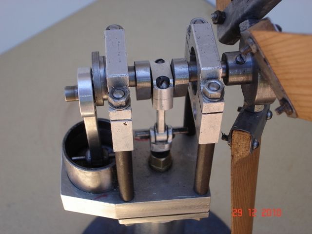
              I usually make my con rods from flat material, usually aluminium 1/4" thick. The width is chosen to take in the width of the big end bearing, plus a little, I mark a centre line, then mark the position of one of the bearing holes, then set the distance on a pair of dividers and mark of the other bearing and centre pop that one, it's then a case of drilling the holes. I use a little bronze bush in the little end bearing, and a ball bearing in the big end, except when the crankshaft design won't allow this, in these cases a split bronze bearing is held in place with a cap held in place by bolts. Here's one of each.

              I do ramble on a bit.

              Ian S Ctest 041 (640x480).jpg

              #219501
              Brian John
              Participant
                @brianjohn93961

                Jason : with my small boring bar…maybe smiley  I did have to open up a tailstock die holder today that was a bit too small to take my dies. The boring bar handled that okay.

                Or perhaps make the cylinder as best I can with the boring bar and then drop an already machined 2 to 3mm thick disc down the cylinder and Loctite it in position : we now have a flat bottom cylinder.

                Edited By Brian John on 05/01/2016 13:53:12

                #219512
                pgk pgk
                Participant
                  @pgkpgk17461
                  Posted by Brian John on 05/01/2016 13:49:24:

                  Jason : with my small boring bar…maybe smiley I did have to open up a tailstock die holder today that was a bit too small to take my dies. The boring bar handled that okay.

                  Or perhaps make the cylinder as best I can with the boring bar and then drop an already machined 2 to 3mm thick disc down the cylinder and Loctite it in position : we now have a flat bottom cylinder.

                  Edited By Brian John on 05/01/2016 13:53:12

                  Or a tube with an interference fit disc tapped in? Or not worry abut it being flat bottomed.. just drill it and bore to the drill taper and make the piston tip to the same angle with the top side? Od not even bore it, just drill since the displacer is a loose fit.

                  The one I'm slowly building (butchering) uses glass cyinders and pistons. I like the idea of seeing the movement.

                  #219615
                  Brian John
                  Participant
                    @brianjohn93961

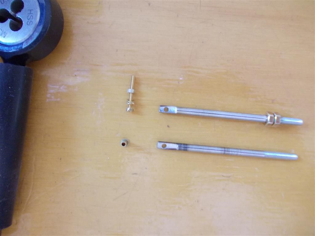
                    I made the connecting rod (13) today. I actually made four of them, two of which have been discarded. I decided not to drill the hole out to 2mm on the flat of the rod ; I have left it at 1.8mm. It will not now accept the 2mm rivet as per the instructions when fitting to the piston joint (14) but I will use a 10BA screw and nut with Loctite to hold it together instead. I thought drilling a 2mm hole was really pushing it too close to the edge of the rod. I have put 12mm of M3 thread on the other end so I can fit two lock nuts. This will allow me to make adjustments to the length of the connecting rod.

                    connecting rod.jpg

                    Edited By Brian John on 06/01/2016 07:02:40

                    #219748
                    Brian John
                    Participant
                      @brianjohn93961

                      I had a go at making the displacement cylinder today. I am getting there but the process has raised a number of questions. I made the bullet shape by producing a 30 degree taper and then rounding it off by hand using a large file. Jason : you are right. Turning the taper using the top slide wheel is much easier than I thought it would be…no handle required.

                      1. Why is it the piston made of aluminium ? I hate this stuff and my lathe does not like it either. It gums up my drill bits and my reamers and I find it almost impossible to tap. I have to drill and tap for an M3 grub screw that will hold the piston rod in position but I doubt it will be successful. I have had problems in the past tapping aluminium. If the piston HAS to be aluminium then I may have to make a brass sleeve and tap that and Loctite it in position in the piston.

                      2. My lathe chuck always gets very hot when working with aluminium. I noticed this a few weeks ago when I was making the aluminium columns (part 30). Why should this be ? Brass does not cause the same problems.

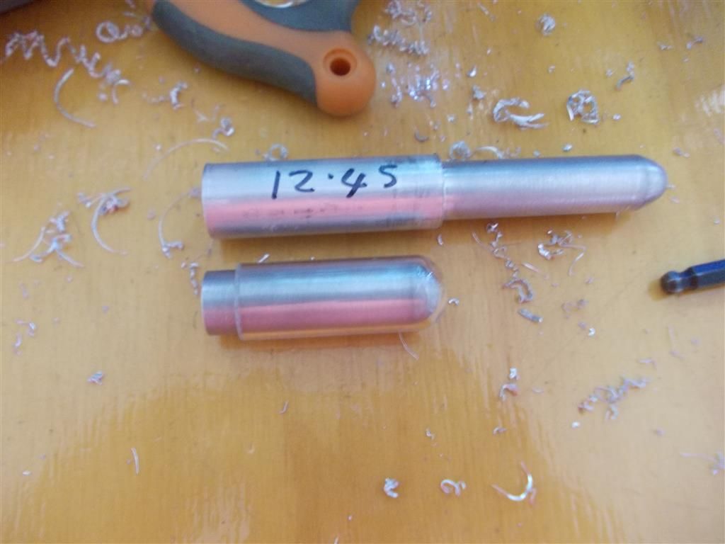
                      3. The ID of the glass cylinder is 13.2mm. The instructions say to make the piston 12.5mm but this seems like a very sloppy fit. You can see in the photo that I attempted to make one to this size (actually 12.45mm) but then stopped and made another one to 13mm diameter. This seems a much better fit and still plenty of room for free movement ie. it does not touch the sides of the glass tube. Any thoughts on this ?

                      displacement piston 1.jpg


                      Edited By Brian John on 07/01/2016 06:28:15

                      #219754
                      Hopper
                      Participant
                        @hopper

                        Brian there has to be room between the displacer piston and the cylinder ID for the air being displaces from one end to the other to flow unimpeded. Also, there has to be room for the piston to move up and down without touching the cylinder at any point — sometimes a bit tricky if the alignment of the piston rod and bushing are not quite spot on, or as the bushing wears a bit. Half a millimeter clearance all round is not unusual, so a total of 1mm difference in diamter.

                        #219756
                        Danny M2Z
                        Participant
                          @dannym2z

                          Brian, what type of aluminium alloy are you using? Something like 2024-T3 is nice to machine, the cheesy soft stuff from the usual suspects (B**nings etc) is crapola.

                          * Danny M *

                          #219758
                          Brian John
                          Participant
                            @brianjohn93961

                            This comes from Norweld in Cairns. Hopper may know what it is.

                            Why aluminium ? I am thinking of making a piston out of brass tomorrow.

                            #219762
                            Michael Gilligan
                            Participant
                              @michaelgilligan61133
                              Posted by Danny M2Z on 07/01/2016 07:56:06:

                              Brian, what type of aluminium alloy are you using? Something like 2024-T3 is nice to machine, the cheesy soft stuff from the usual suspects (B**nings etc) is crapola.

                              * Danny M *

                              .

                              Brian

                              Heed Danny's advice ^^^

                              On the "Cheese Scale of Hardness" you need Parmesan, not Brie.

                              .

                              You are doing very nicely, and the lathe is obviously well-sorted … so the problem must be either the material or the cutting tool [angles, height, edges, lubricant …]

                              Invest in some hard alloy of known composition, and then experiment with tool & technique.

                              MichaelG.

                              .

                              Edit:  From this distance, Norweld looks like a great firm … but I suspect that their stock alloys are chosen for 'bending and welding' performance rather than 'machining'.

                              P.S. … Lots of information  here

                              Edited By Michael Gilligan on 07/01/2016 08:46:04

                              Edited By Michael Gilligan on 07/01/2016 08:51:21

                              #219767
                              Michael Gilligan
                              Participant
                                @michaelgilligan61133

                                Brian,

                                This is a convenient chart of recommended tool angles.

                                Another one here.

                                … Note the 35° 'Back Rake' for Aluminium

                                … Compare with the 0° sugested for Brass.

                                MichaelG.

                                Edited By Michael Gilligan on 07/01/2016 09:54:07

                                #219768
                                Ajohnw
                                Participant
                                  @ajohnw51620

                                  As this started life as a kit they may well have provided a suitable grade of aluminium so was that any different when it was machined compared with what you have bought.

                                  The usual problem with machining it is melting and sticking to the tool. Also the fact that it's rather abrasive – aluminium oxide forms on fresh surfaces virtually immediately causing other problems. This boils down to the need to polish HSS tool surfaces with a slip stone. Given a suitable speed that should work out well. If it still melts and sticks slow things down.

                                  It often doesn't take well to the use of abrasive cloths of one sort or another. 3in 1 oil or any old cycle oil helps

                                  Drilling has similar problems but rather than messing with a decent sharp drill it just takes practice. Not too fast and a higher feed rate than some one might use on say mild steel. The drill has to keep cutting and mustn't rub. There will still be a need to flick swarf out of the flutes with something sharp – say a scriber but it shouldn't stick but will if people get it wrong.

                                  Can't understand why some one should have trouble tapping it. Hand soap makes a decent lubricant. One problem might be not applying the right amount of pressure. Taps don't pull themselves in – they can but results are likely to be poor. Same with dies.

                                  Going back to earlier suggestions about indexed tipped tools that was probably ignored this type removes the need for polishing hss and works well on other materials as well.

                                  **LINK**

                                  These will fit the el chepo 10mm indexed tip holders sets. I think they supply this size of tip on the smaller ones as well. They are micro polished because aluminium does tend to wear coatings off. There are several similar tips available. Also different shapes.

                                  John


                                  Edited By Ajohnw on 07/01/2016 09:47:58

                                  #219772
                                  Kettrinboy
                                  Participant
                                    @kettrinboy

                                    Displacer piston viewDisplacer piston viewFor a displacer piston the ideal metals are stainless steel or titanium bored out to give a wall thickness of 0.25 mm or so , they have low heat conductivity and can stand high temps ,and the piston is as light as it can be , just to give you an idea the one in the pic is stainless steel, an aluminium bung is then usually loctited in the open end but there must be no air leakage into the piston or that can stop an engine from working , the reason Bengs have specified a solid aluminium piston is as its a solid piston there are no leakage problems and it is the lightest metal apart from magnesium to make a solid piston from , if you make a solid brass piston it will probably be too heavy unless you bore it out to lighten it and fit a bung , but if this is done properly it will be as good or better than a solid aluminium one

                                    Edited By Kettrinboy on 07/01/2016 10:17:41

                                    Edited By Kettrinboy on 07/01/2016 10:18:22

                                    Edited By Kettrinboy on 07/01/2016 10:23:14

                                    #219779
                                    Brian John
                                    Participant
                                      @brianjohn93961

                                      AjohnW : they did supply a small piece of aluminium. I have not used it yet because it is only 51mm long ! I may give it a go tomorrow if I have time.

                                      I will give some thought to making a hollow brass piston and how the piston rod may be attached to that.

                                      If I do have problems drilling and tapping my already constructed piston, then I still have a few ideas up my sleeve to make it work.

                                      #219789
                                      Andy Holdaway
                                      Participant
                                        @andyholdaway

                                        I had no problem making the displacer piston with the supplied material, although there wasn't much to hold in the chuck. It did seem like a fairly hard aluminium, but machined and tapped with no problems.

                                        #219791
                                        Ajohnw
                                        Participant
                                          @ajohnw51620

                                          You'll probably still have problems with aluminium unless the tool is suitable Brian. If you can't polish them and keep a sharp edge it might be better to really slow the machine down. That's more on the lines of what I do on my Boxford to save grinding different angles but they still need to polished. Ordinary parting off blades are more of a problem – really good at getting it to stick to the tip. Just have to watch for when and if this happens. I suspect it's related to feed rate but sometimes I get a bit stick. The problem is a little like the one when it's drilled.

                                          The angles Michael's post suggests in the first link for aluminium would be ok on mild steel really or brass. For aluminium I would increase the side rake into the cut to circa 20 degrees on a small machine to limit the load on it. Then try that and if there was any signs of self feeding – unlikely – reduce that angle. Same with other material. This is what this angle controls. This worked rather well on a peatol.

                                          You might find that 35 degrees back rake weakens your tools too much. A decent amount is 15 degrees for most materials. All of my turning during training was done with that amount of material. Big lathes with a tool holder that held 5/16 bits at 15 degrees.

                                          If you have a grinder what you could try is grinding the top angles first and then polishing it on emery with a bit of cycle oil on it on something fairly flat. Then grind the sides. It's very easy to round off cutting edges when a stone is used and this will leave you with a sharp edge. If you choose to also polish the side that cuts just do it enough to polish up a short distance from the edge – pushing the tool back and forth and not side to side. Using the round edge of the wheel for grinding leaves a depression but that doesn't matter on the sides – things aren't so good on the top. It has to be polished for a decent distance in from the edge.

                                          John

                                          Edited By Ajohnw on 07/01/2016 11:08:40

                                          #219800
                                          Brian John
                                          Participant
                                            @brianjohn93961

                                            Andrew : ''there wasn't much to hold in the chuck'' …..that is why I did not use it. I might give it a go tomorrow : do half and then turn it around and do the other half. That usually never works for me but what the hell !

                                            I had problems turning and parting off the Norweld aluminium. I would try to slow the lathe down but it would stop ! It never stops when I am turning brass, no matter how slow I run the lathe. From the above information, I would guess that the tools I am using are not suitable for aluminium. This would also explain the less than perfect finish I am getting ; I had to finish off with 1500 grit sandpaper.

                                            #219805
                                            Ian S C
                                            Participant
                                              @iansc

                                              If you are going to machine a displacer for the motor, a bit of mild steel would do the job better than brass (stainless would be better). The way I do It is to bore out the bit of metal to about 1 mm less than the finished out side diameter, with a flat bottom to the hole (a suitable slot drill will get most of it. Part it off 2 mm past the end of the hole. Now take a bit of steel and turn it to fit the bored hole, and drill a small hole right through this. Without taking the mandrel from the chuck, slip the displacer on with a drop of Loctite, go and have a cuppa, come back and turn the out side down to size, and face off the end by 1 mm. Heat the displacer, and (now you can use them)with a glove on your hand you should get the thing of the mandrel. The hole you put in stops suction holding things up. A little aluminium plug is needed for the cold end with a hole to take the displacer rod, I thread it, and extend it to about half way up the displacer and make a light weight disc to fit inside, helps to stabilize it, and acts as a dam, keeping the hotter air at the hot end. Stick the aluminium plug in with Loctite, and use Loctite on the rod. It's a tedious little job, and the smaller it is the worse it is. With your's I think I would just drill it, then round the end.

                                              Ian S C

                                              #219846
                                              Ajohnw
                                              Participant
                                                @ajohnw51620

                                                I your lathe in the low speed range via the belt Brian ?

                                                Whoops – Just found the 2 speed ranges in the manual though. Low speed 120-1500 and high 320 to 3000 rpm.

                                                At some point you might want to look to see if there is any chance of making a pulley to give you circa 800rpm max. I suspect you would find that more useful.

                                                John

                                                #219861
                                                Brian John
                                                Participant
                                                  @brianjohn93961

                                                  My lathe is set on the low speed range : Hopper has measured it's top speed on the low range as 2000 RPM and marked the divisions on the speed dial accordingly. The book is way out. Most of the time I am operating at less than 800 RPM. I cannot remember going higher than this. Hopper did suggest that I make another pulley to replace one already on the lathe and this would give me twice as much power. I think that would be a good idea. Many times I want to go slower but I cannot because the lathe stops. It seems to be more of a problem lately. My gut feeling is that the motor seems to lack the grunt it had when new but this cannot be.

                                                  Edited By Brian John on 07/01/2016 16:34:39

                                                  #219905
                                                  Ajohnw
                                                  Participant
                                                    @ajohnw51620

                                                    I suggested 800rpm as during my training few lathes went significantly faster than that. Turning mostly various steel alloys and also mild steel. Hand fed initially as well. I've stuck with that sort of range with my Boxford and may make rude noises when some one says that materials must be cut at higher speeds. As used my Boxford has a top speed of 650rpm but I can push that up with the inverter but generally don't. To get the belt drive set up to a max speed of 1300 rpm I need to change the pulleys on the motor as you do. Otherwise they can be changed from 200 to 650 via the counter shaft. If 200 proved to be too fast for some material when HSS is used I simply stick a carbide one in.

                                                    This does cause me a bit of a problem at times. Microscopes for instance often use 6mm dia thumbs screws, knurled for for circa 25mm along their length with a variable length M2.5 or M3 thread on the end and even a longish at this scale reduced size plain section in between. I could remove the material with rather light cuts which would take a long time unless I upped the speed a lot. If I tried to just take 2 the stuff would probably bend so I size it in one go. It's probably quicker this way actually.

                                                    Since that period manufacturers started fitting 2 speed motor on many medium sized lathes due to the use of carbide tools but people managed without that previously. Jobs may take longer – so what as far as I am concerned. If I'm boring thin shell and things start chattering I just stick the back gear in even when using indexed tipped tools. That brings the max speed down to 127 rpm.

                                                    John

                                                    #219930
                                                    Brian John
                                                    Participant
                                                      @brianjohn93961

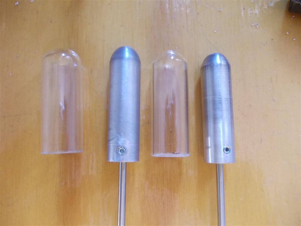
                                                      I did not have any trouble drilling and tapping that piston made from the Norweld aluminium. But I decided to make another piston closer to the diameter in the instructions using the supplied aluminium. This was much better : the aluminium machined like brass and my lathe did not get hot either. I wish I knew what it was so I could buy more from somewhere.

                                                      Anyway, now I have two displacement pistons (12.9mm and 12.7mm). I may make a 12.5mm piston tomorrow as per the instructions but my gut feeling is that it would be too loose.

                                                      displacement piston 2.jpg

                                                    Viewing 25 posts - 251 through 275 (of 764 total)
                                                    • Please log in to reply to this topic. Registering is free and easy using the links on the menu at the top of this page.

                                                    Advert

                                                    Latest Replies

                                                    Home Forums Stationary engines Topics

                                                    Viewing 25 topics - 1 through 25 (of 25 total)
                                                    Viewing 25 topics - 1 through 25 (of 25 total)

                                                    View full reply list.

                                                    Advert

                                                    Newsletter Sign-up