Stirling Engine : Laura

Advert

Stirling Engine : Laura

Home Forums Stationary engines Stirling Engine : Laura

Viewing 25 posts - 226 through 250 (of 764 total)
  • Author
    Posts
  • #218114
    Ian S C
    Participant
      @iansc

      The stove top fan is to my own design, all the plans are in my top 2", as usual, I tend to just put things together to fit around the stuff I'v got, and the general theory of Stirling Engines. The piston is made from window weight iron, and has a skirt thickness of just over 1 mm, and a crown of 3 mm, the little end bearing is fitted to a 3/8 UNF hole in the crown.

      Normally I don't use gaskets, but if one is needed I use Loctite liquid gasket (can't remember the number). I have in the past tried proper gasket paper with the idea of forming a thermal break, for example, between the hot cap and the cold end of a BETA motor.

      Ian S CStove top

      Advert
      #218115
      Brian John
      Participant
        @brianjohn93961

        I have plenty of the proper ''paper'' gasket material which I purchased for building model steam engines. I think I will use that for sealing the frames.

        I will try to solder up that damaged cylinder ; I may need for for something.

        #218120
        Michael Gilligan
        Participant
          @michaelgilligan61133
          Posted by Ian S C on 28/12/2015 10:49:05:

          The stove top fan is to my own design, all the plans are in my top 2", as usual, I tend to just put things together to fit around the stuff I'v got, and the general theory of Stirling Engines. The piston is made from window weight iron, and has a skirt thickness of just over 1 mm, and a crown of 3 mm, the little end bearing is fitted to a 3/8 UNF hole in the crown.

          .

          Thanks, Ian

          MichaelG.

          #218160
          Andy Holdaway
          Participant
            @andyholdaway
            Posted by Brian John on 28/12/2015 10:50:34:

            I have plenty of the proper ''paper'' gasket material which I purchased for building model steam engines. I think I will use that for sealing the frames.

            Brian, I think the gasket paper may be a good idea. I finally completed my engine last night, and after an hour of frustration and burnt fingers conceded defeat!

            I used silicon to seal everything, and either didn't do a good enough job, or over did it and bunged up the air passage.

            I will pull it apart tonight and see if I can see anything obvious. I've checked all the usual things like good piston seal, everything free etc. so it's a bit of a mystery at the moment.

            #218165
            Brian John
            Participant
              @brianjohn93961

              Andrew : I bought this kit as a project in how to use a lathe rather than mindlessly churning up scrap metal with no purpose in mind. I very much doubt that I will end up with a functioning Stirling engine

              #218168
              Andy Holdaway
              Participant
                @andyholdaway
                Posted by Brian John on 28/12/2015 17:26:24:

                Andrew : I bought this kit as a project in how to use a lathe rather than mindlessly churning up scrap metal with no purpose in mind. I very much doubt that I will end up with a functioning Stirling engine

                Brian, that was my purpose too, but it would have been nice to have something that works – how hard can it be?!?!?

                #218170
                Brian John
                Participant
                  @brianjohn93961

                  It would seem that Stirling engines are much more difficult to build than steam engines. The fit of the parts must be just right. I also read somewhere that the gap between the piston and the cylinder cover at TDC must be as small as possible. I don't know if this is true but it is something to look at. The kit has been designed to make these adjustments.

                  Edited By Brian John on 28/12/2015 17:40:18

                  #218175
                  Andy Holdaway
                  Participant
                    @andyholdaway

                    The gap in my displacer cylinder is tiny – I had to adjust the rod as the piston was hitting the end of the cylinder. I'll pull it apart later and see if I can see what's going on. I'll take the work cylinder cap off first and see if I can feel any wind coming up the hole from the displacer.

                    My next project is the Bengs Karl engine. It's an I.C. hit & miss engine – I'm much more confident with petrol and a spark!

                    #218213
                    Brian John
                    Participant
                      @brianjohn93961

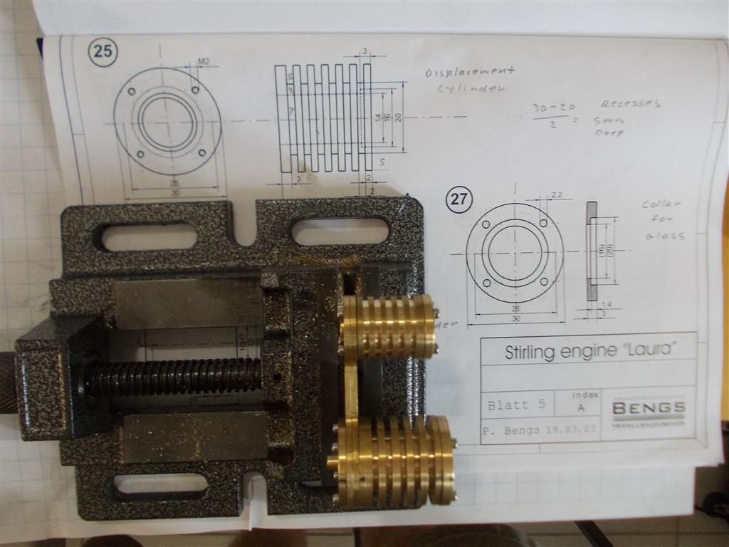
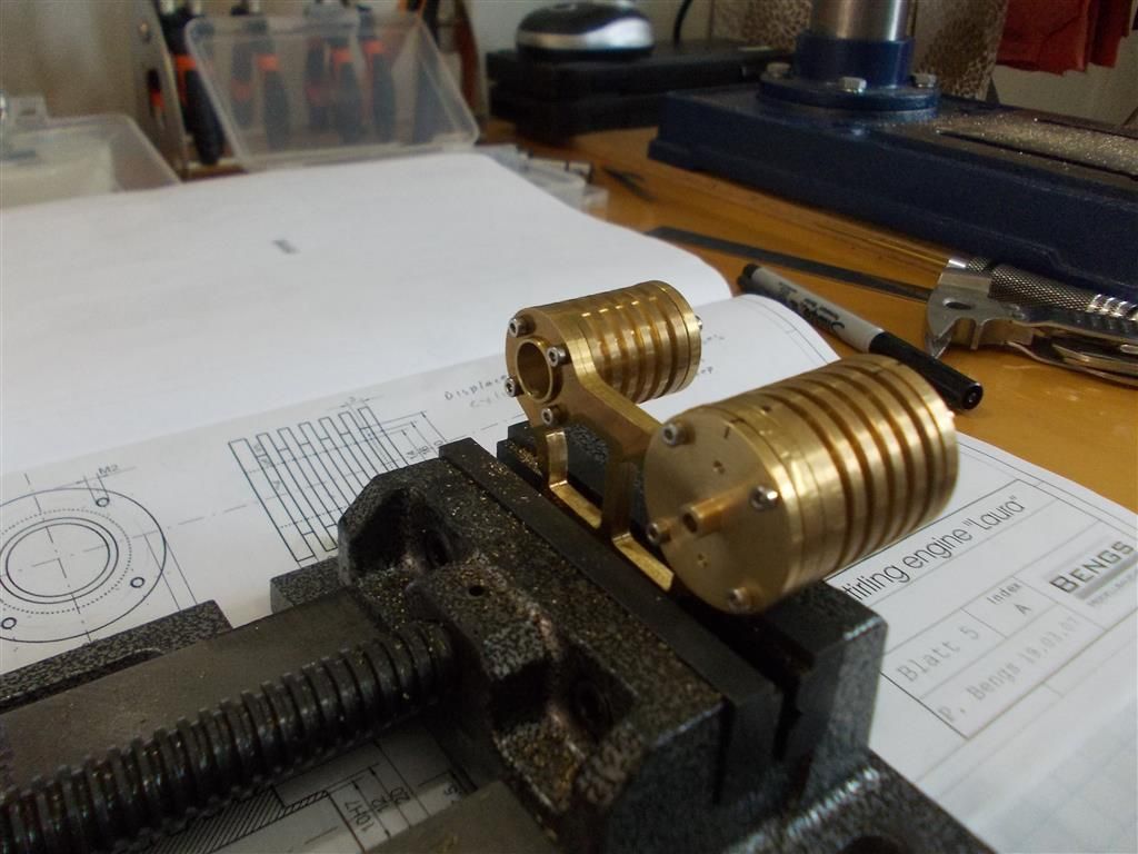
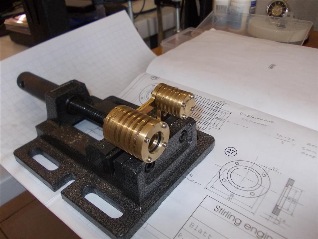
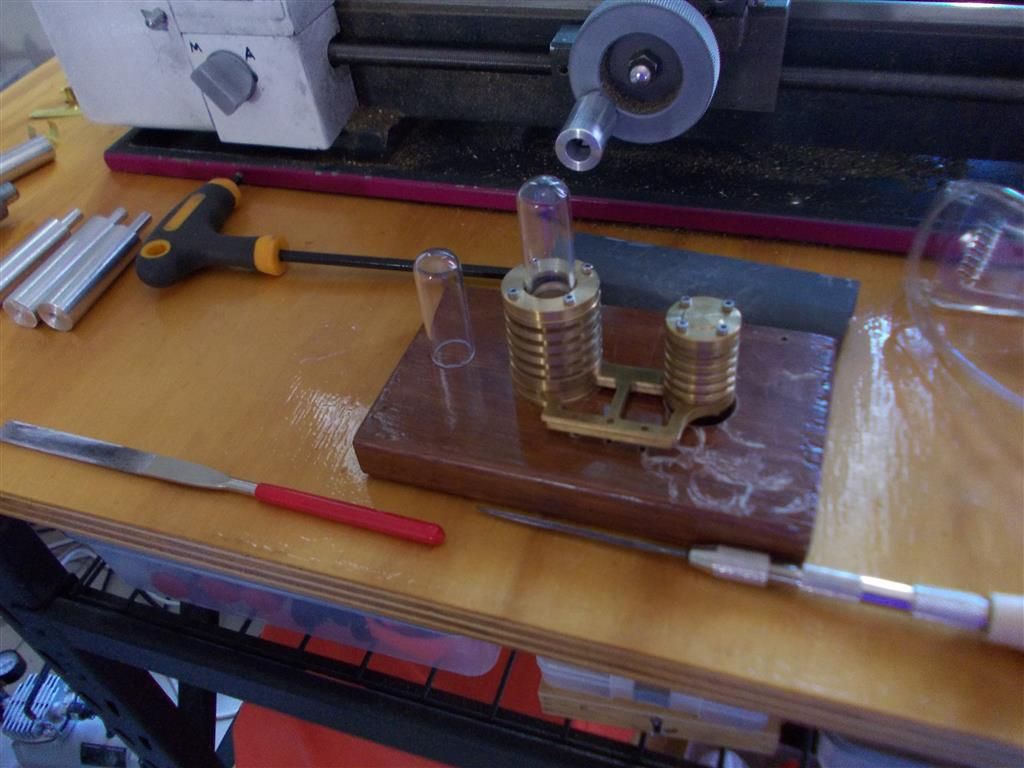
                      I finished the covers and collar for the displacement cylinder today. I am not quite happy with the fit of the glass tube collar (part 27) so I may make another one tomorrow. I am not sure what went wrong there !

                      I am still a bit puzzled about the 16mm X 3mm recess in the end of the displacement cylinder (part 25). I was told it was to allow for expansion of the 20mm rubber collar which fits neatly in the recess of the glass collar (part 27). But having put it all together, I disagree with this theory.

                      drilling and tapping 6.jpg

                      drilling and tapping 7.jpg

                      drilling and tapping 8.jpg

                      #218216
                      Hopper
                      Participant
                        @hopper

                        It looks like you are making good progress Brian.

                        Couple things you can do to avoid drilling through bore again might be to make a drilling template, a circle of steel like a thick flat washer that fits over the end of the cylinder and has the hole drilled in exactly the right place. (If the first hole is not quite right, you can keep drilling more holes until you get it right. Use the lathe to mark the circle on the drill jig washer at the diameter where you want the centre of the hole to be.

                        Then make sure the bore is dead square to the end of the cylinder that bolts to the frame. These should ideally be machine in one set up to ensure perfect squareness. If not, you can make mandrel with a taper of about .001" that the bore fits over, without removing the mandrel from the lathe, and then machine the end of the cylinder square with the bore that is a tight fit on the freshly turned mandrel. An alternative to the taper is a neat fitting parallel mandrel and a spot of Loctite to hold the cylinder on firmly.

                        Then check/machine the other end of the cylinder so it too is square to the bore. This is the surface the cylinder sits on when drilling it.

                        I would sit the cylinder straight on the drill press table, perhaps with a pair of toolbit blanks under it as parallels so you can drill through the cylinder without hitting the drill press table. A nut and bolt and pair of washers with the bolt runnign through the bore and a T slot etc in the table will clamp it down nice and firm. This eliminates the cylinder getting out of square in the vice, which maye or may not sit perfectly square as bought.

                        I wouldn't use gaskets or silicone to seal. I would use a spray can of Hylomar gasket sealer to just mist a thin thin layer of sealer on the necessary surfaces. Let it dry out completely before assembly then put together in the normal manner. Allied Bearings carries the Hylomar. A little of it goes a long way. But it does not make blobs and strings inside the engine like silicone will.

                        #218218
                        Brian John
                        Participant
                          @brianjohn93961

                          Hopper, thank you for the information. The reason it went through the side is because I initially drilled the pilot hole in the wrong place. I should have left it as a 2mm hole (it may have still done the job) but I tried to ''move the hole over'' with a 3mm drill bit….that was never going to work. You can do that with 2mm thin plate but not when drilling through 27mm of brass. The drill bit just deflects and follows the original hole. I will see if I can salvage it with some delicate soldering.

                          The Hylomar sounds good. I was still uncertain what to do there ; I know it should not be anything thick.

                          NOTE : I think the 16mm X 3mm recess in the displacement cylinder is for the glass tube to rest on when it is inserted through the collar. The glass tube is 15.4mm OD.


                          Edited By Brian John on 29/12/2015 08:12:56

                          Edited By Brian John on 29/12/2015 08:13:21

                          #218427
                          Brian John
                          Participant
                            @brianjohn93961

                            Although I did not really need to, I made another collar (part 27) for the glass tube. How do I drill holes in the collar to match the holes which have already been drilled and tapped in the end of the displacement cylinder ?

                            My solution is to draw a 30mm circle on a sheet of paper with a compass then carefully cut out the circle with a pair of scissors. I then lay this circle on top of the cylinder and mark the hole positions on the transparent paper. This circle of paper can then be laid on the collar and the position of the holes marked with a punch.

                            I have used this method before with good results but it seems a bit primitive. Is there a better way ?

                            #218647
                            Brian John
                            Participant
                              @brianjohn93961

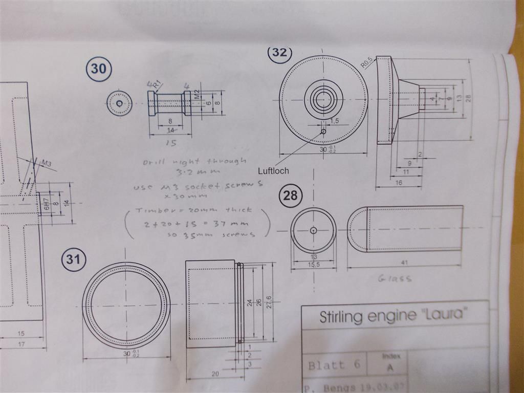
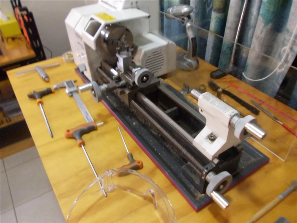
                              I was not going to make a meths burner out of brass as per the instructions (parts 31 and 32) but I realised today that I have not yet done any taper turning on the lathe . After thinking about how to do it, I realised that my lathe does not have a handle on the top slide wheel. This is going to make it difficult to get a smooth cut. Why would they leave the handle off the top slide ? The lathe instruction book actually shows a handle on the top slide wheel in all the diagrams. I think I am going to have to make a handle and drill/tap the top slide wheel for it as I doubt that I can get a good finish without it. Am I missing something ?

                              taper 1.jpg

                              taper 2.jpg


                              Edited By Brian John on 31/12/2015 10:06:20

                              #218654
                              JasonB
                              Moderator
                                @jasonb

                                You should not use the handle if you want smooth cuts, both hands or at least finger and thumb of each hand on the wheel and that way you can feed continuously . Using a handle can induce up and down movement which will show up on the finished surface.

                                Reason they did not fit one is lack of room and not needed as topslide is usually used for fine feeding only.

                                #218691
                                Ian S C
                                Participant
                                  @iansc

                                  My lathe has 2 handles on the top slide wheel, a short one and a long one. The long one soon got a bump against the tail stock, and broke off, the short one got bent. Replaced the broken one with one that rotates, but as Jason says, don't use the handle when actually removing metal.

                                  Brian, your coming along well.

                                  Ian S C Happy new year in about half an hour.

                                  #218767
                                  Brian John
                                  Participant
                                    @brianjohn93961

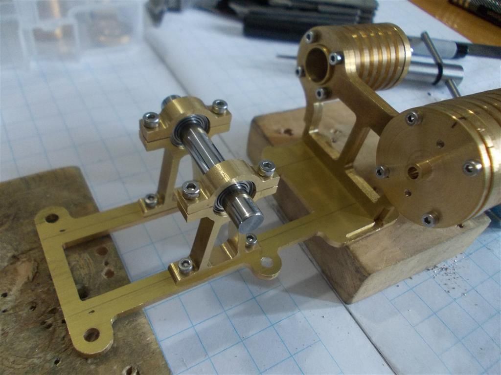
                                    I have now drilled and tapped the bearings supports and the base plate. I had a few dramas but I got there eventually. The main cylinder assembly is just sitting on the base plate at this stage. The instructions call for it to be soft soldered to the base plate but the more I think about it, the less I like that idea. If something needed to be readjusted it would be difficult to do it. Unsoldering is a messy business !

                                    I am thinking of drilling and tapping the base plate and the cylinder support frame so that I can use some brass angle and bolt it all together with 2mm socket screws. Are there any problems with that idea that I have not considered ?

                                    bearing supports.jpg

                                    Edited By Brian John on 01/01/2016 06:16:22

                                    #218775
                                    JasonB
                                    Moderator
                                      @jasonb

                                      Why not drill & tap the baseplate, drill the bottom of the cylinder support (clamp the two bits together as you drill down the joint) and then just use cap heads from above which will match the way the bearing supports are fitted

                                      #218779
                                      Brian John
                                      Participant
                                        @brianjohn93961

                                        Jason : I do not think there is enough meat to drill the bottom of the cylinder supports. I am not sure I follow ?

                                        #218789
                                        Kettrinboy
                                        Participant
                                          @kettrinboy

                                          Whichever way you decide to finally fix the cylinder assembly to the base plate wait until you have the whole thing running and then adjust it until it runs at its fastest until tightening it down as stirlings wont tolerate much if any misalignments that cause friction , just choose a method that gives a little wiggle room to let it all run as freely as possible, the brass angle method sounds pretty good to me , leave say 0.5 mm clearance in the holes for fine adjustments before tightening down.i definitely woulnt go down the silver soldering route as it could distort the base plate then you would have problems.

                                          #218793
                                          Ian S C
                                          Participant
                                            @iansc

                                            I would drill the base plate, and tap the holes in the bottom of the stand, put the screws in from underneath, use a reasonable size screws, or the whole thing will rock as it runs. One of my flame lickers is mounted that way, and only has three 1/8" Whitworth screws, and it flexes a bit, but as it hasn't broken I'm not fixing it, my usual 3/16"/10 32 UNF would be what I would replace them with, 5 mm would be OK.

                                            Ian S C

                                            #218815
                                            Ajohnw
                                            Participant
                                              @ajohnw51620

                                              I would follow either Jason or Ian's suggestion Brian. Probably Jason's as I would use countersunk headed from underneath which would leave zero scope for adjustment.

                                              One thing you should check on your drill – are the drills square to the table? Often they can be adjusted on one plain. Out of square can cause holes to wander about. An automatic centre punch helps or in in critical places a centre drill first – those can be pulled a little with care.

                                              A small toolmakers square can be a useful thing to have about. They usually come with 3 blades. On straight, one angled at each end and a narrow one that can be used to measure. The blades are 100mm / 4" long.

                                              winkThe manic method on larger holes is to scribe a box with a height gauge and pull the drill central as the tip goes in. Done correctly the drill will break the scribed lines on all sides = positioned to better than 0.001".

                                              John

                                              #219401
                                              Brian John
                                              Participant
                                                @brianjohn93961

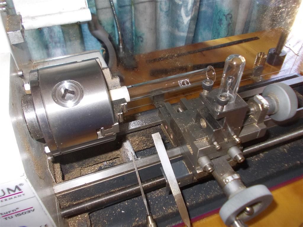
                                                I have cut two glass cylinders/tubes from the supplied test tubes. I put masking tape around the test tube where it is held in the chuck. I held a diamond file on its edge to cut through the tube while the lathe was set to a low speed. The triangular file would have been better but it is not a diamond file so it would not cut very well. Once I had cut through it then I cleaned up the edge with the flat of the diamond file and then removed it from the lathe to give it a final polish with 1500 grit sandpaper.

                                                I would have liked to make a tool holder for a dremel diamond wheel as somebody suggested above but I am still waiting for some square bar stock. For some reason I never ordered any square bar before…only round !

                                                Next step is to make the aluminium piston to fit the glass cylinder. I am not looking forward to this at all because I have to try to round the end of the piston by hand to get a good fit in the end of the cylinder.

                                                glass cylinder 1.jpg

                                                glass cylinder 2.jpg

                                                Edited By Brian John on 05/01/2016 06:25:23

                                                #219437
                                                Martin Connelly
                                                Participant
                                                  @martinconnelly55370

                                                  Make a stiff card radius gauge to check against if you are going to manually make the radius. It does not need to be a perfect curve as it going to be in the bottom a test tube that is probably not a perfect hemisphere anyway. It just needs to look good in the tube.

                                                  Martin

                                                  #219445
                                                  Brian John
                                                  Participant
                                                    @brianjohn93961

                                                    I still think it is bad idea making things out of glass and it only complicates the issue of making a piston to fit. I know they chose glass because of it low thermal conductivity but I have seen similar Stirling engines with stainless steel cylinders. If I can get this engine to work with the glass cylinder then I will try to replace it with a stainless steel one at a later stage.

                                                    Andrew : did you get your Stirling engine to work ?

                                                    Next problem is the connecting rod for the working piston : I have to drill a 2mm hole through the 3mm steel rod. This is not going to be easy. I would hardly think I can mark the hole with a punch like I would usually do. How would you go about doing this and ensure that the hole is in the centre ? I have a bench drill and a drill press vice.

                                                    .


                                                    Edited By Brian John on 05/01/2016 11:12:15

                                                    #219472
                                                    steamdave
                                                    Participant
                                                      @steamdave
                                                      Posted by Brian John on 05/01/2016 11:09:05:

                                                      Next problem is the connecting rod for the working piston : I have to drill a 2mm hole through the 3mm steel rod. This is not going to be easy. I would hardly think I can mark the hole with a punch like I would usually do. How would you go about doing this and ensure that the hole is in the centre ? I have a bench drill and a drill press vice.

                                                      Brian

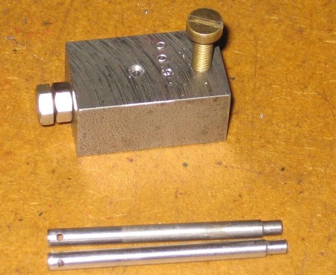
                                                      Make a simple (reusable) jig. More pics in Cross Drilling Jig album, but I don't know how to post more pics in this reply.

                                                      Dave
                                                      The Emerald Isle

                                                      chj5.jpg

                                                    Viewing 25 posts - 226 through 250 (of 764 total)
                                                    • Please log in to reply to this topic. Registering is free and easy using the links on the menu at the top of this page.

                                                    Advert

                                                    Latest Replies

                                                    Home Forums Stationary engines Topics

                                                    Viewing 25 topics - 1 through 25 (of 25 total)
                                                    Viewing 25 topics - 1 through 25 (of 25 total)

                                                    View full reply list.

                                                    Advert

                                                    Newsletter Sign-up