Stepper Motor Wiring

Advert

Stepper Motor Wiring

Home Forums Electronics in the Workshop Stepper Motor Wiring

Viewing 6 posts - 26 through 31 (of 31 total)
  • Author
    Posts
  • #625580
    Stuart Smith 5
    Participant
      @stuartsmith5

      Alan

      Are you sure?

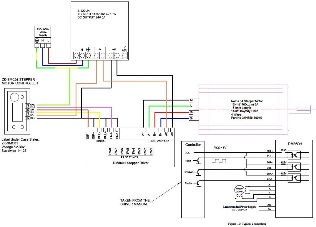
      The purpose of the 24v 5a power supply S120-24 is to provide the power for the steppers and with your latest diagram it isn’t.

      Stepper drivers are usually supplied with dc.

      Stuart

      Advert
      #625583
      SillyOldDuffer
      Moderator
        @sillyoldduffer

        I agree with Stuart: the first diagram is right, the second is wrong. As I noted this driver runs on either AC or DC.

        The manual says 'Input voltage 18-80VAC or 26-113VDC'

        And this photo shows the AC terminals also have + and – markings.

        No need to add an AC transformer, the DC supply is suitable.

        Dave

        #625630
        Alan McDade
        Participant
          @alanmcdade29638

          Thank you John and Martin for your really helpful advice.

          The DM860H driver I have does not show the "+" or "-" after the AC in the High Voltage silk screen printing like in the photo above. I do note that it does say "VAC: 18V~30V VDC:24–110V" in the same place as in the photo above. So I take it then, I am OK to connect a DC 24V supply from the PSU to the DM860H driver and remove the step down transformer as shown below:

          draft wiring diagram v3.jpg

          Again, many thanks for your really helpful advice which has given me confidence in what I am doing with this little project.

          #625632
          Stuart Smith 5
          Participant
            @stuartsmith5

            Alan

            I looked for a manual online and found the same one that Dave has added a picture of.

            If you look at that, the negative needs to go to the end terminal and positive to the next one. On your proposed layout you have the connections the other way round.

            Stuart

            #625638
            Robert Atkinson 2
            Participant
              @robertatkinson2

              I agree that no transformer is needed. I don't think it matters what way around the DC supply is connected to the AC/DC terminals. This is because A. The input almost certainly has a bridge rectifier which will "switch" the current the right way, and B. the control inputs are optically isolated.

              Robert G8RPI.

              Edited By Robert Atkinson 2 on 21/12/2022 12:32:23

              #625640
              Alan McDade
              Participant
                @alanmcdade29638

                Stuart, – many thanks – I have fixed on my diagram.

                Robert – thanks for your help.

              Viewing 6 posts - 26 through 31 (of 31 total)
              • Please log in to reply to this topic. Registering is free and easy using the links on the menu at the top of this page.

              Advert

              Latest Replies

              Viewing 25 topics - 1 through 25 (of 25 total)
              Viewing 25 topics - 1 through 25 (of 25 total)

              View full reply list.

              Advert

              Newsletter Sign-up