Stepper motor driver connections

Advert

Stepper motor driver connections

Home Forums Electronics in the Workshop Stepper motor driver connections

Viewing 17 posts - 26 through 42 (of 42 total)
  • Author
    Posts
  • #348853
    Joseph Noci 1
    Participant
      @josephnoci1

      How far did the shaft turn? Was it close to the start, only half way, etc.?

      To try:

      Connect Pins 8 to PLS+ , Pin 9 to DIR+.

      Connect PLS- and DIR- to grnd ( pin 20)

      What does your software do? Is it an Indexer or a CNC type ( 3D printer, mill)???

      Can you index the motor around slowly – say sort of 10RPM or less? Do it slowly so that if the pulse width is not great the motor at least does not lose (too many) steps, and see if you can do a 360deg index.

      You need to know how many pulses come out of Pin-8, and how many steps/rev you have set your driver to.

      The motor is (normally) 200steps/rev and if you set the driver to 400steps/rev, you need to obviously get 400 pulses out of pin-8 for 1 rev..

      Joe

      Advert
      #349083
      Hnclad
      Participant
        @hnclad

        Hi, apologies for not getting back sooner, other chores have been piling up while I have been playing with stepper motors.

        The information that you guys have given me was enough for me to wire up the driver/motor with confidence and see if it worked. There are other things I still have to absorb about stepper motors.

        The driver and motor are set up my work bench, my index head is on the lathe doing other work, so to answer Joe's question of did I get a 360 rotation with the dip switch set of the 400 steps on the driver, I did. I have a piece of electrical tape on the motor shaft and it made a complete turn but I cannot verify accuracy until my lathe is freed up.

        To answer Joe's question, can I index the motor at 10rpm. I cannot, the software doesn't have this feature. There is a "Goldilocks" slider that sets the speed at not too fast and not too slow, in the sweet spot the motor runs smooth and quietly.

        I'm going to leave it there for now, it works, I just have to verify the accuracy. I want thank everybody who has shared their time and knowledge helping me to not only get the motor and driver working but also the amount of knowledge I have learned. Thanks a lot.

        Kind Regards

        Dave

        At the moment we have a light snow fall and zero degrees. This is spring in Ontario.

        #349085
        Joseph Noci 1
        Participant
          @josephnoci1

          Dave, Glad it appears to work. Could you maybe just tel us how you eventually connected everything up? Motor series/parallel? PC port pins to the driver direct or with additional +5V supply? … Etc…

          Thanks

          Joe

          #349484
          Hnclad
          Participant
            @hnclad

            Hi To answer your question Joe the motor was wired as bipolar series. The phase connection being the terminal ends of the coils were connected to the A+/A- and B+/B-. The centre taps of the coils were connected separately for each pair of coils and insulated. The 18vdc was connected to the appropriate terminals on the driver. That's pretty straight forward. The step/pin8 was connected to pulse+ connection and the dir./pin9 was connected to the dir. connection. Pulse- and Dir.- were connected to pin 20/gnd. There was no 5volt connection. I am creating an album so I can upload photos of this set up and data sheets etc. but please be patient. This is a busy time for me. The weather is perfect for felling dead and dying trees that me and the wife marked last year. After felling they have to be bucked into fire wood lengths, split and piled for drying for next winters fire. It doesn't leave much time for me to get in the workshop or on the computer.

            I should explain how I got to this point. 5 years ago I started construction on Wildings Elegant Skeleton Clock, I came across a construction of a cnc. set up for a dividing head, this included the software to run it. The constructor had used a circuit board which he modified, I was interested in the project but was too busy with the clock to start soldering a board. Another amateur clock maker had built the project using a motor and driver from Arc Euro and said it worked fine. I visited their site saw they had a motor and driver on sale and bought them knowing absolutely nothing about stepper motors or drivers. Fools rush in etc.The original constructor used a unipolar motor out of a photo copier so I though I should use a the motor I had in that configuration but quickly realized I couldn't mix 2 power sources. I also realized that 18 to 50 volts was a high voltage for a driver circuit board so it must also run the motor. I was stuck, so since I had already paired the centre taps I would insulate them switch on the 18v. power and see what happened. The motor turned and I was elated. But, when I cut my first wheel/gear the last tooth was very thin and other teeth seemed thinner than they should be. My notes from that time didn't record what settings I used for the steps but I pretty much tried all of them. I never solved the problem and anxious to move on with the clock I put the parts in a box, in corner. Although I moved on I never forgot about the project and when I joined this forum recently I thought I was a good opportunity to see if I could solve it.

            Hope this explains things a little better.

            Regards David.

            #349488
            Joseph Noci 1
            Participant
              @josephnoci1

              Hello Dave,

              Well , seems you have it sorted now! The connections are sound, and for an indexing head the way you are using it you certainly need not worry about series / parallel connections and torque variation, etc…

              Never having cut clock-gear teeth ( or any gear teeth, for that matter..) I cannot really comment of the 'thin' teeth much, other than probably the obvious –

              If only the last tooth appears thin, then the diameter of the blank was maybe not correct for the number and depth of cut of the teeth?

              Ditto if all the teeth appear  somewhat thinner as well? Or not quite the correct profile cutter used?

              Also assuming the correct number of teeth were cut, ie, the index per tooth was correct ( stepper pulses versus index head gear ratios and all that..) and an extra tooth did not creep in somewhere..

              Joe

              edit – fix the usual sextagerian typo's

              Edited By Joseph Noci 1 on 09/04/2018 06:50:39

              #349541
              SillyOldDuffer
              Moderator
                @sillyoldduffer

                Posted by Hnclad on 09/04/2018 03:21:12:

                … But, when I cut my first wheel/gear the last tooth was very thin and other teeth seemed thinner than they should be. My notes from that time didn't record what settings I used for the steps but I pretty much tried all of them. I never solved the problem and anxious to move on with the clock I put the parts in a box, in corner. Although I moved on I never forgot about the project and when I joined this forum recently I thought I was a good opportunity to see if I could solve it.

                Hope this explains things a little better.

                Regards David.

                As a fully unqualified amateur gear-cutter (third class) I sympathise!

                Even when the stepper and controller are set up properly, other things can go wrong. For example (don't ask how I know), the wheel blank must be held firmly. It only has to move slightly to ruin the gears. Likewise, actually cutting the gears and adjusting to the material used may take a bit of practice.

                You don't have to use a PC to drive the motor controller, in fact in a grubby workshop you might prefer not to!

                Home build alternatives based on a Arduino microcomputer include:

                • Gary Liming's Step Indexer here
                • Written up as a build article by Carl Wilson in Model Engineering Shop Issue 249, and discussed in these two threads: **LINK** and **LINK**
                • This video series by MyfordBoy also features Gary's Step Indexer

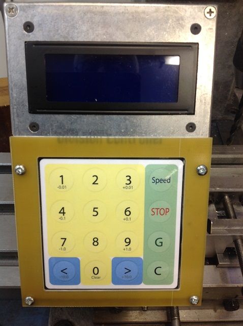
                Not everyone likes the sort of nested menu interface Gary uses to set-up his indexer. John Stevenson asked if anyone could do similar without nested menus and I offered this keypad operated solution with additional features; the software and documentation can be downloaded from dropbox.

                Dave

                #349552
                John Haine
                Participant
                  @johnhaine32865

                  There is also the ward indexer which I use and works well. See my album from which this photo is taken…

                  photo.jpg

                  img_0561.jpg

                  I second the point about making sure the wheel is properly fixed, having produced a 48 tooth ratchet wheel when I was aiming for 60…

                  #350013
                  Hnclad
                  Participant
                    @hnclad

                    dscn0401.jpgp1010004.jpgstep motor info.204122018_0001.jpgHi. Thank you all for your input, I have uploaded some photos to my album, I hope they help. Wildings clock was my second clock, I had constructed Allan Timmins long case clock a few years before. I used a direct indexing plate on the head stock spindle of my Myford ML7 to cut the wheels and pinions. I am familiar with the possibility of a single point cutter causing enough vibration to move the wheel blank. I always use multi tooth cutters from Thornton Successors. I like the direct indexing plate as it offers good locking during machining, Something I worry about with cnc. Also with cnc. you have to make provisions for backlash. That being said it could be handy for the odd weird numbered wheel count not on my index plate. To answer Joe's question on a large wheel blank giving a wrong wheel count. The software program I have provides the number of index's required, no more, nor less, so a larger blank would have thicker teeth since the cutter width is fixed and visa versa for a smaller wheel blank.

                    I have attached a phot of the connections for the driver & motor using bipolar configuration. There is also a photo of the stepper motor data. I pulled the motor apart, there are 8 coils on what I call the stator. The iron core of each coil has grooves machined in it that seem to match the "teeth" on the rotor. Does this make it a micro stepping motor? John Haines assertion that since the driver's lowest step count is 400 and the normal count 200 steps it would seem that I would have to double the wheel count. That wasn't necessary and I have no explanation for that. After I cut the wheel with a thin tooth I mounted an aluminum disk in the lathe chuck coated in layout blue. Using a scriber in the tool post I marked every index for a 96 tooth main wheel. At the end the final index had over shot the first line. I can only assume that there is some incompatibility between the driver I have and the software which was written for a different driver. step motor info.204122018.jpg

                    #350014
                    Hnclad
                    Participant
                      @hnclad

                      Hi seems I was unable to add more text after attaching the photos. To answer one last question from John about the ability of the software to index odd number of index's that would use a partial step. The software has the ability to account for this by adding or reducing the number of steps so that a complete rotation is accurate. Hope that makes sense.

                      As Joe remarked, all spelling mistakes due to the elderly must be forgiven. I think I can give you a few years Joe, I was born and bred in the steam era, started work in 1959, 5 year engineering apprenticeship and as my email says a H.N.C. lad. Loughborough College of Further Education.

                      Kind Regards. David.

                      #350015
                      Joseph Noci 1
                      Participant
                        @josephnoci1

                        Hello again David.

                        The grooves in the rotor and stator form the poles of the magnets that then force rotor alignment with the rotating magnetic field as the motor 'steps'. This is standard construction, and has no bearing on microstepping at all. The natural step position of the motor is easily felt when you rotate the rotor by hand – most commonly available steppers show 200 steps when you do that, ie, 1.8deg / step. Motors are available with more steps/rev, and less as well – some of the paper feed steppers in cheap printers have 72step/rotation ( 5deg steps) etc.

                        A full step of your motor occurs when one phase of the pair is energised, and then de-energised while the second winding is energised. This steps the rotor at one magnetic detent at a time. as the energising sequence repeats.

                        1/2 stepping occurs when , instead of de-energising winding-1 and energising winding-2, winding 1 is kept on, and winding-2 is then turned on as well. The rotor magnets then align mid-way between the two winding magnetic positions, ie, at the half step point. This is then 400 steps/revolution.

                        By varying the applied currents to each phase the rotor can then be made to take up any intermediate position between the magnetic mechanical detents, and so microstepping is made possible.

                        Since your motor is a 200 step/detent motor, and your controller cannot do less than 400steps/rev, your setup will require that the software generate 400 steps to rotate the rotor 1 full revolution.

                        John Haines assertion that since the driver's lowest step count is 400 and the normal count 200 steps it would seem that I would have to double the wheel count. That wasn't necessary and I have no explanation for that.

                        I do not understand the above statement in conjunction with the one below…

                        Using a scriber in the tool post I marked every index for a 96 tooth main wheel. At the end the final index had over shot the first line

                        The first implies that since you did not have to double the wheel count, the end result was correct.

                        But the second says you overshot the mark – So I am not sure what actually happened…

                        The only way to know definitively if the step counts match up, is to know how many step pulses your software gives for one rotor revolution. This can be extrapolated to actual workpiece rotation knowing the gear ratio between stepper rotor and workpiece drive shaft.

                        How do you set up the indexer to generate say 180 teeth? Do you enter the stepper to workpiece gear ratio as well?

                        ALL stepper drivers that use STEP and DIRECTION inputs, and that can be set to 200/400/800, etc, steps/rev work the same way – The software generating these two signals cares not what driver is attached – it generates ONLY step pulses and the number of pulses is related to what the driver has been set to ( 200/400 pulse/rev, etc) and the associated gear ratios.

                        Your second statement of the overshoot on 96teeth – how much was the overshoot? around 1 tooth? or a lot more? If the overshoot is small, I am sure it has nothing to do with the driver settings, or the number of steps the software has output. I believe the problem lies in the gear ratio – Re-check that ratio carefully. If you got that wrong by a small amount, then what you are seeing is very possible. The stepper is also not losing steps, because that would have resulted in an undershoot..

                        Joe

                        #350023
                        Hnclad
                        Participant
                          @hnclad

                          Hi Joe your explanation of how a stepper motor works was appreciated. I'll try to explain more clearly my last post. First before the indexing program can be used you have to input the indexing reduction. This is in 2 parts, first is the actual dividing head 1:60 the second is the gear belt or timing belt reduction. In my case this was 1:3 (16 teeth to 48 teeth) this part allows you to use the stepper motor to drive the dividing head. It's easier than building a direct drive. The brass worm wheel and hardened screw on the dividing head are manufactured parts as are both of the gear belt and pulleys. I can't see how there can be any fault here. Once that is put into the program you are asked to put in the number of teeth or indexes. I entered 96 teeth and then indexed 96 times, the dividing head rotated a full turn plus a little bit extra, about half a tooth thickness. That is what I meant when I said the although the lowest steps on the driver is 400 and according to you that should only index the dividing head halfway round. It didn't and it actually went half a tooth past the last index, which I assume was an accumulation of a small error on 96 teeth or indexes. I can't explain that any other way.

                          Hope this helps. David

                          #350074
                          Joseph Noci 1
                          Participant
                            @josephnoci1

                            Hello David.

                            Forgive the length of this post, but it needs doing!

                            Ok, lets see if we can get closer to the issue…

                            Since the Dividing head went 360deg ( plus a smidgeon) when you indexed 96 teeth for the full 360 degree circumference, the motor is stepping for all intents the correct number of steps, ie, 400 steps per rotor rev. This also means that your software seems to be sending 400 step pulses for one rotor rev. I would expect the software Creator did this with intent, since most of the inexpensive stepper drivers have 400steps/rev as their lowest setting ( as yours does).

                            Anyway, if the problem lay in that direction, it would be very obvious – the dividing would be in error by half a rotation!

                            That said, just to get some numbers down:

                            Your total gear ratio is 1:180. So one 360 deg rotation of the table will require 180 Stepper rotations, which is 180*400steps/rev = 72000 step pulses from the software for one Table rotation.

                            For your 96 tooth setup:

                            One tooth is a table rotation of 3.75deg. This gives a stepper rotation of 3.75*180 ( the gear ratio) = 675 deg.

                            So for every tooth indexed, the stepper must rotate 675 degrees, or 750 steps…

                            For all that diatribe…The stepper 'STEP' ratio to Table tooth index is 750 steps per tooth ( for the 96 tooth example), and an accumulative error of say one motor step per tooth indexed (751 step pulses instead of 750..) would give 72096 step pulses for one table rotation. That equates to (72096/400) = 180.24 stepper rotations in stead of 180 rotations per one table rotation.

                            The actual error in tooth is then 180.24/180 ( the gear ratio..again..) = 1.0013333 table rotations instead of one rotation – That is an error of 0.48 degrees at the last tooth position. This is not insignificant, as your tooth index is 3.75 deg. the error is nearly 8% or so. However, you indicate a half tooth error – or closer to 2degrees..closer to a 50% error..

                            Basically, in order to quantitatively determine if there is an accumulative pulse error in the sequence you need to be able to measure the (small) error at the end of the index sequence. All my gaff above was really to try show that the error has nothing to do with the stepper driver, or the steps/rev setting for your motor. Any error there would be large. A cumulative error of 1 or 2 step pulses per tooth index sequence would cause a problem though..

                            This leaves a few possibilities. Either the software is not computing the pulse count correctly ( not using floating point, rounding errors, etc), or there is electrical noise which is being seen as indiscriminate pulses. The latter is unlikely due to the OPTO input to the stepper, but still possible if your ground connections are not sound. Backlash may also be a problem, but I assume you take care of that by taking up any backlash in the gears before you start indexing?

                            In order to try eliminate some of these , could you do these tests : Note that you should try be as accurate as possible in determining the last tooth stop position each time.

                            Setup the indexer to do the following number of teeth per 360deg rotation –

                            60 teeth, then 120 teeth, then 70 teeth, and last, 150 teeth.

                            For each one, setup, take out any backlash in the direction of rotation, mark carefully the start and then index all the way round till the last tooth, and note the error. THEN, zero the setup again ( to your original start mark) and REPEAT that test again( remembering to eliminate backlash..), and when done repeat once more ( do each set thrice..). Note the error each time, and especially, note if the error is the SAME each time round for that tooth count.

                            What this should show:

                            If there is error, and the error is the same within a sequence of 3, then it is not random electrical noise causing inadvertent step pulses, but probably due to the software.

                            If the error differs each time for each of the three tests of the same tooth count, then the driver is seeing pulses that are not being generated by the Software – possibly due to grounding of the driver motor supply ,or grounding of the PC relative to the Stepper supply, or relative to the Index table/lathe, etc.

                            If the 60 tooth and 120 tooth tests show no error, or VERY SMALL error, while the 70 and 150 tooth tests have noticeable errors, then it possibly a software rounding problem..

                            NOTE: try to ensure the same test conditions each time – ie, repeat each sequence with the same process each time – lathe power on sequence, etc. If it is electrical noise, you should try to ensure the same noise generator ( the lathe, whatever) is powered at the same place in the sequence, etc.

                            Again, forgive the long post, but it can be tricky to find problems that are seemingly this subtle. Hope I have not chased you away…

                            Joe


                            Edited By Joseph Noci 1 on 13/04/2018 15:20:43

                            #350556
                            Hnclad
                            Participant
                              @hnclad

                              Hi Joe, first let apologize for my delay in replying. We have had a late winter storm here in Ontario that has lasted 4 days. We were12 hours without electricity yesterday. Today Tues. I spend all day reattaching the snow blower to my tractor and moving 8 inches of slush and ice off my driveway so we can go food shopping tomorrow. I have read your lengthy post several times, and I think I have my answer. That is, it is probably the software that is causing the extra indexing problem. I am happy with that assessment. I think considering the age of the computer (15 years!) I use which has a printer parallel port and Windows ME software I should upgrade to a more modern system that has been generously proposed on this forum. My old computer could fail at any time. I have my answers and thank you for your help, I think we should end this thread as everyone else seems to have done. David.

                              #350557
                              Joseph Noci 1
                              Participant
                                @josephnoci1

                                Hello David,

                                I do not think the issue has necessarily anything to do with the computer, if the software you are using was designed to run on that computer and operating system. If the problem is in the wiring,grounding, etc, a new computer may be no improvement. I do not think everyone else has 'closed' this thread – they just have not anything to say yet, is all..I have three old Windows-2000 machines running Mach-3, all with printer ports, all more than 15 years old ( one is nearly 20 years old!) , with no Break out boards, and they all work fine on my CNC mill, routes and engravers!

                                Just trying to help..

                                And sorry about your snow woes..Don't get much of that here in Namibia..

                                Cheers..

                                #350560
                                Michael Gilligan
                                Participant
                                  @michaelgilligan61133

                                  Keep it going, Chaps

                                  It's a joy to observe an interesting and useful discussion taking place at such distance !!

                                  MichaelG.

                                  #350561
                                  John Haine
                                  Participant
                                    @johnhaine32865

                                    David, just a suggestion of something to try…set the division ratio to 95 and step 96 times and see where it ends up.

                                    #350658
                                    Hnclad
                                    Participant
                                      @hnclad

                                      To Joe and everyone else, your enthusiasm and help is much appreciated. I should have made myself clearer in my last post. I said due to the age of my computer it could break down. Last week when I started the computer up to try some of the suggestions I was greeted by an error message. <windowsroot>system32hal.dll I phoned my local computer repair shop where the technician told me the problem was most likely a failure of the mother board or the hard drive and the standard charge to determine which was $40. So I have to pay $40 to decide if I want to pay hundreds of dollars for a mother board or hard drive and I would still have an indexer that was over indexing. It was an easy decision. Again i have appreciated your help. David.

                                    Viewing 17 posts - 26 through 42 (of 42 total)
                                    • Please log in to reply to this topic. Registering is free and easy using the links on the menu at the top of this page.

                                    Advert

                                    Latest Replies

                                    Viewing 25 topics - 1 through 25 (of 25 total)
                                    Viewing 25 topics - 1 through 25 (of 25 total)

                                    View full reply list.

                                    Advert

                                    Newsletter Sign-up