Steam Engine Number One
Steam Engine Number One
Home › Forums › Stationary engines › Steam Engine Number One
- This topic has 207 replies, 23 voices, and was last updated 7 February 2022 at 12:58 by
 Andy_G.
-
AuthorPosts
-
9 May 2021 at 17:16 #544086
Iain Downs
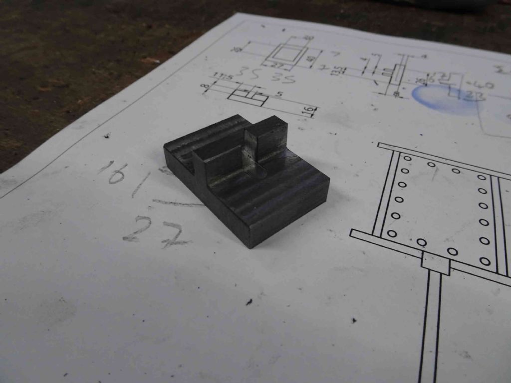
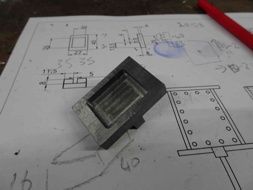
Participant@iaindowns78295So the latest item on the production line was the DValve.
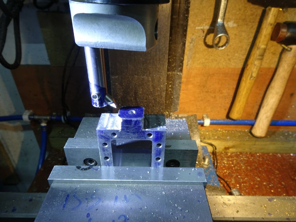
This was a fairly straightforward piece of milling, marred in the first instance by my measure (wrong) once and cut… oh dear … approach.
Second times the charm.
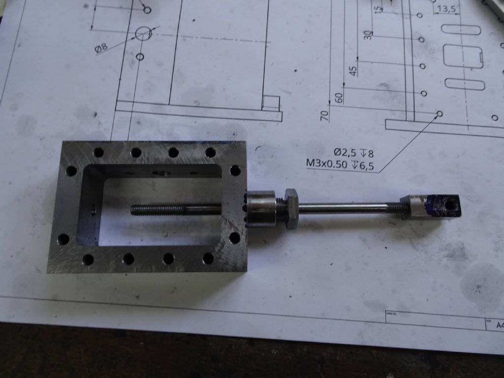
My original drawing had a slot and bar approach to connecting the eccentric rod, but I decided to change it for a gap with nuts and washers (which is what my main source the Stuart 5A has). It may be that the ridge is now not high enough, but the DValve is also easy enough to remake, so I'm not too worried.
Also attempted in this period was the valve chest. Sadly, this failed part way through due to the cutters pulling out of the collet and digging too deep, spoiling the part. It looks like the root cause it not enough drawbar tension, so I hope it will work better this next time!
Iain
30 May 2021 at 10:28 #547769Iain Downs
Participant@iaindowns78295I thought quite a bit more time had elapsed since my last post as it's been busy, but not with good things! I have three pieces of engineering progress to report and I will sandwich the unhappy one between two better outcomes – a management skill apparently!
As well as some frustrations in the shed, my home PC melted down a couple of weeks ago (CPU/Motherboard dead) and it's been something of a struggle to repair it. Apparently I keep PCs for too long as by the time the damned things break down all the parts are obsolete! I am now slightly the wiser on the advances of the last 10 years and am again working. Quite how long it will take to find all the programs I had on the older system (or indeed if I need them), is another story.
However, let's start with some positivity, shall we?
Jason advised on creating some flanges for the steam pipes and I thought that to be a good idea.
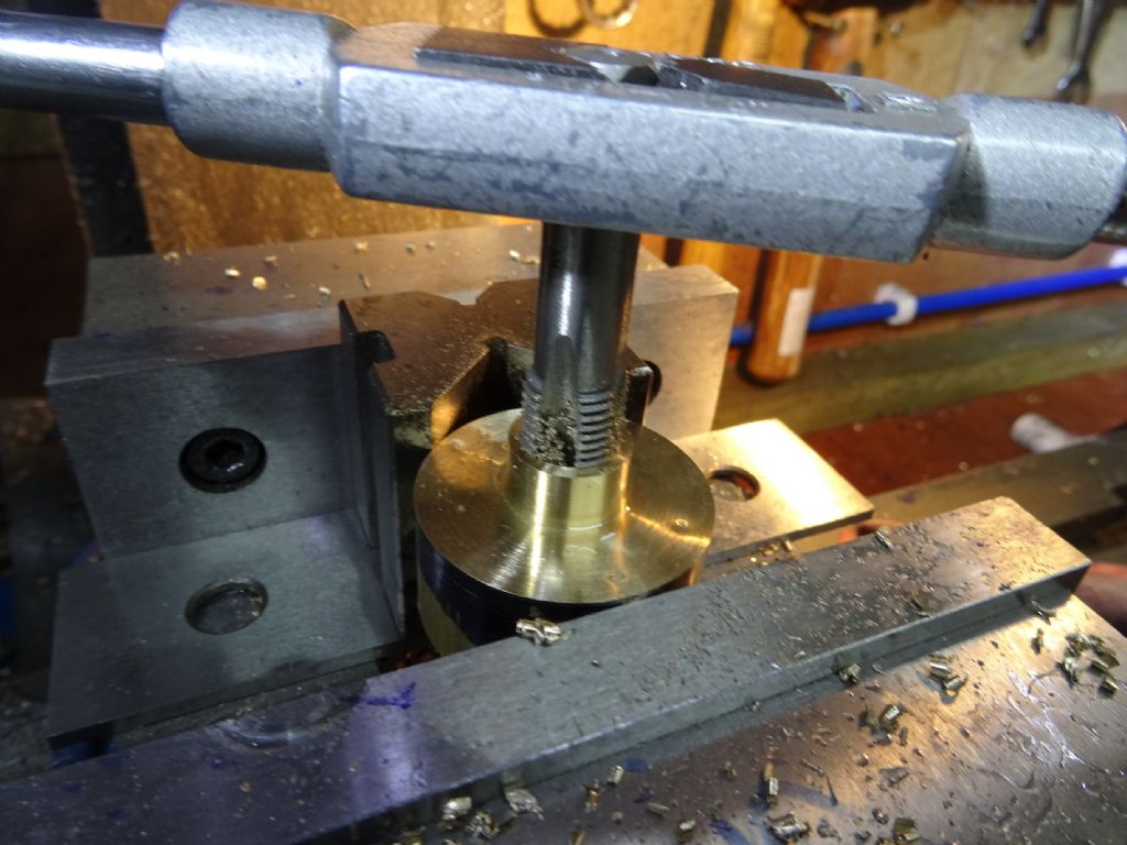
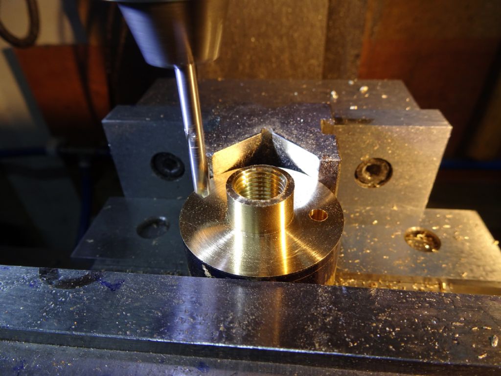
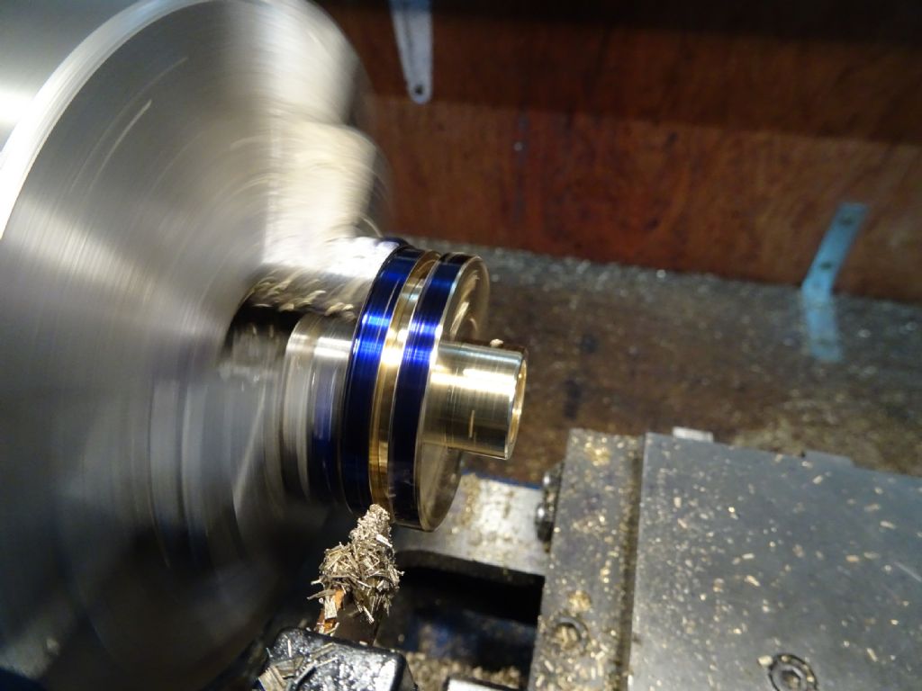
First take a piece of round brass stock face to size and put a 16mm spigot (is that the right word) on each end. The first one held in the 3 jaw, the second one by placing the 16mm end in an ER32 collet. Drill through and tap to 14 bsp. I did have a challenge on the drilling – foolishly cut a pilot hole and then the large drills pulled themselves in and jammed. I didn't want to stone off the edges for a single use, so managed to baby the hole with much wincing.
It turns out that one of my two cheapo carbon steel tap and die sets has 1/4bsp tap and die. Whilst the other tools in the set have lasted about 10 minutes when faced with steel, I'm hoping these will last a bit longer if they only deal with brass.
Next drill some 4mm holes in just the right place (14mm from center.
And return to the 3 jaw to be parted in two
Brass is nice. Why does anyone use steel?
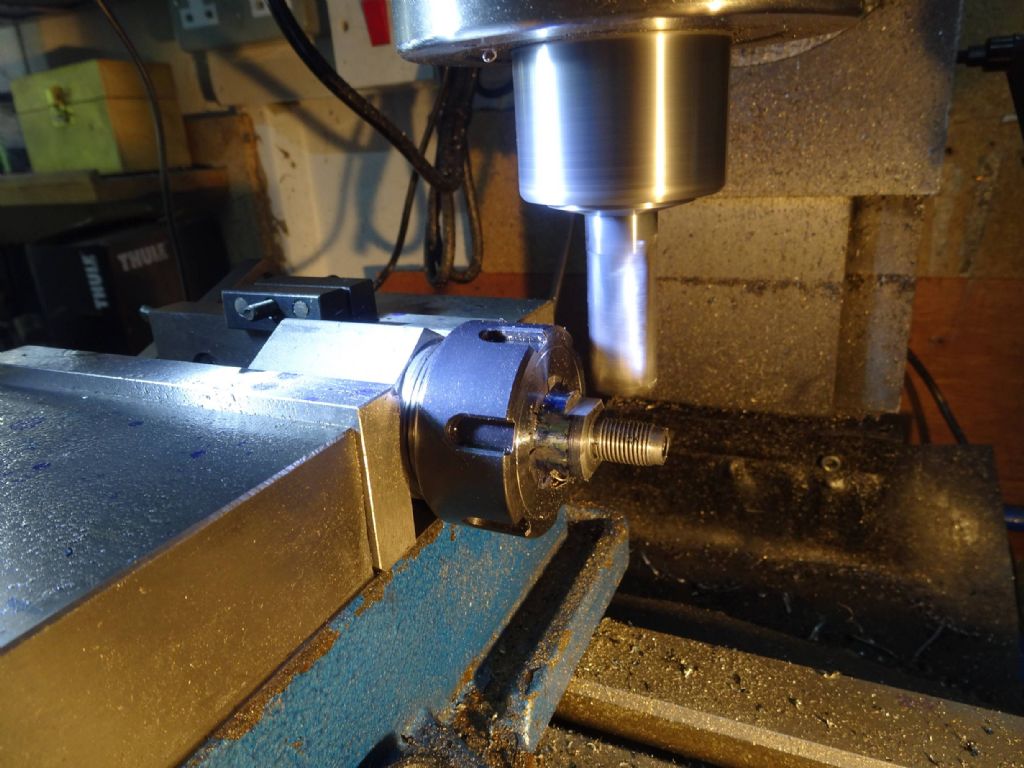
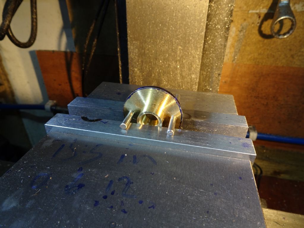
Then put each piece in the mill kept in registration by a pair of pins
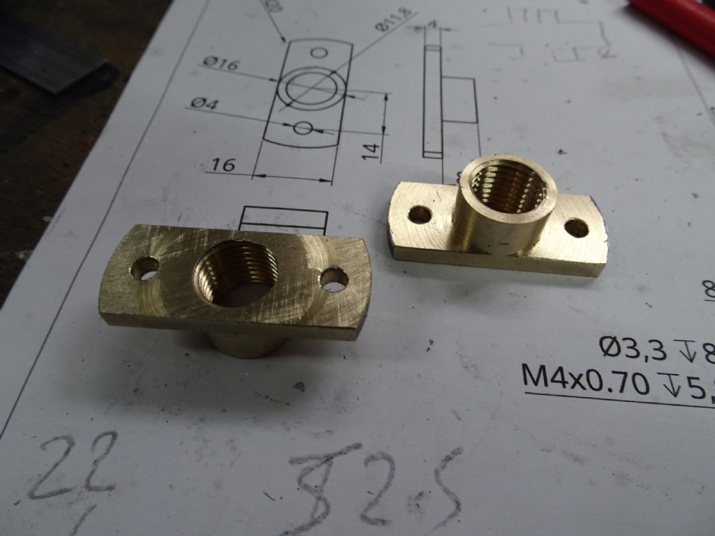
And trim off the top and bottom. Leading to this
Which I'm quite pleased with.
Apart from my drilling challenge mentioned above, I also broke an Ally carbide tip. I thought to see how this would work, but when I was reducing the stub, it caught on the part and – well, let's just say the results weren't good. i had to replace the drive gear on the motor.
I ground myself an nice zero rake HSS cutter which finished the job in style!
And that was the successful job!
Iain
30 May 2021 at 10:55 #547774Iain Downs
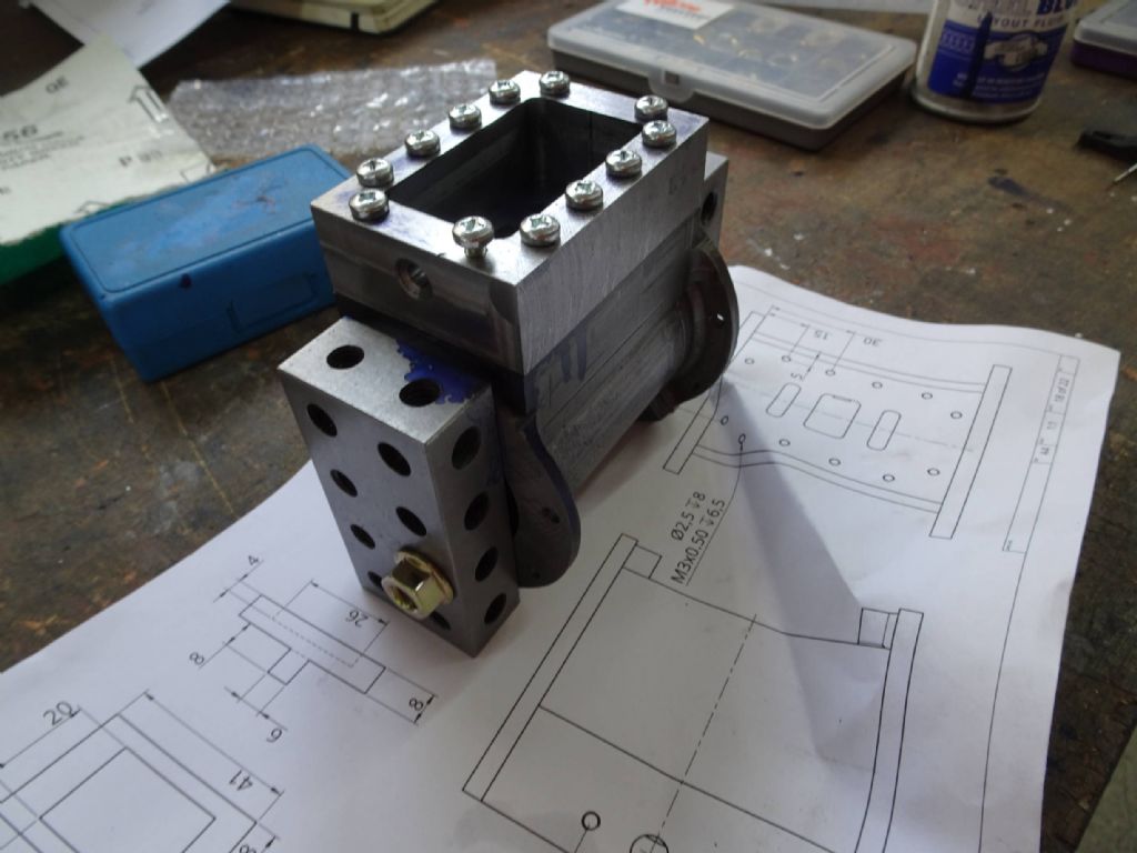
Participant@iaindowns78295The next challenge was to create the valve chest. The pictures below are a mix of the first attempt and the second attempt. I can't quite recall what went wrong with the first attempt, though most likely it was getting a dimension wrong. My second attempt came so close. And for once the failure wasn't my fault (though I will face the judgement of public opinion if need be).
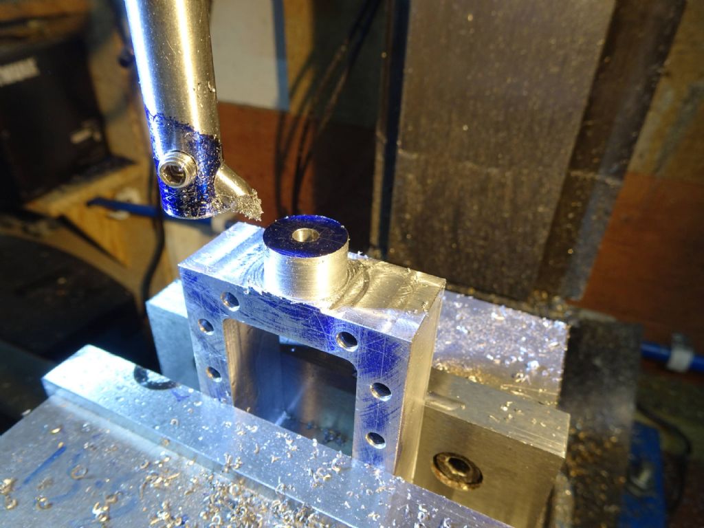
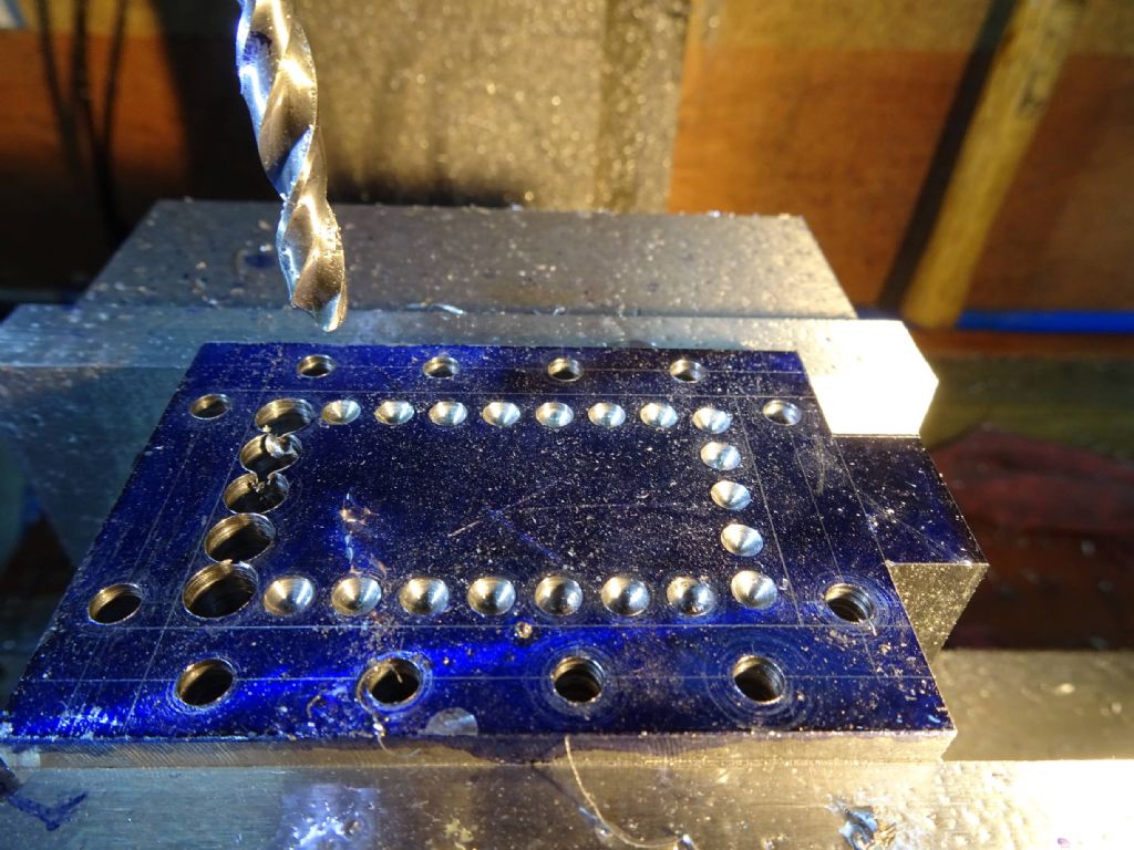
The item is a hollow rectangular block drilled through for bolts into the cylinder and with a stub at one end to contain the steam gland for the eccentric.
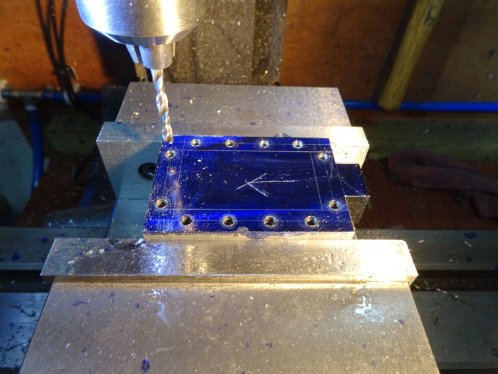
First step was to face to size and then drill the bolt holes.
You can see the stub on the right which will hold the steam gland.
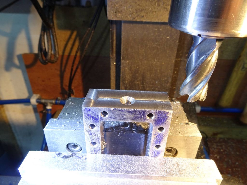
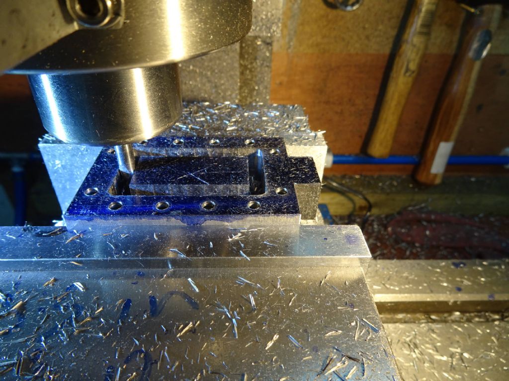
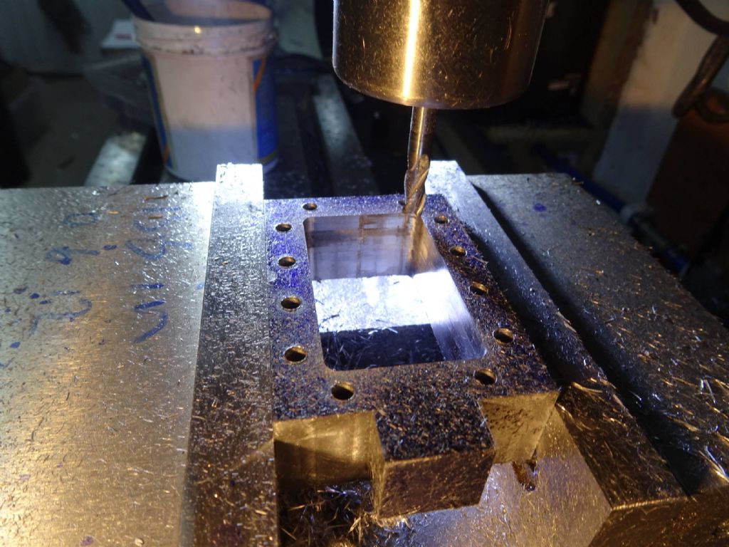
Next to chain drill the inside out before finishing with a milling cutter. This is something I saw on Joe Pie's channel and is supposed to reduce the strain on the cutter or something. Made some sense to me!
and
and
Here's where things get sticky.
And I've remembered what happened to the first attempt. The failure came when milling out the end to leave the stub. I hadn't tightened my drawbar enough and the 10mm carbide cutter pulled out and took too much off.
This time I got further! However then I wanted to turn the stub into a cylinder. I tried any number of ways of mounting this on the lathe with no success. It's too long and there's not enough material to grab and thin enough that it slips into the chuck body. I tried a variety of things with parallels under and round the base, but I couldn't see how I could get something even firm enough to clock in (I'd but in a reamed 5mm hole where the eccentric rod would go through and was/would indicate off that.
I gave some thought to mounting it on a faceplate, but the only angle block I have of the right size is something other than 90 degrees and would have left things out of whack (I looked at 2 4 8 blocks and bolts and clamps, but it was just getting too much).
So I thought, why not bore the outside? I'd done this before and set up my boring head with a brazed carbide cutter, running in reverse (or the head unscrews – don't ask me how I knew).
This lasted about 15 seconds before the carbide cutter objected to the interrupted cut and cracked.
At this point I turned out the lights, went inside and found my PC had expired.
A pause for respect for a much loved an faithful motherboard.
Now we've got the bits and they're all back together (though it seems my purchase of Toshiba hard drives was a mistake as they appear to be expiring, requiring the purchase of another hard drive
 ).
).Made myself a reverse boring bar and set to on the stub.
Quite pleased with the result (so far).
Now I have a 10x1mm tap and die set so the idea was to thread this to 10×1 to give some nice controllability to the gland. I have a set of 9.2mm drills (eBay, of course), chucked one up drilled out and inserted the tap.
The tap fell straight in. Didn't touch the sides. Yes. Words Were Spoken!
This is the only one I don't want to take the blame for. The b***y drill was bent! how can someone sell you a new drill which is bent!? For that matter how can you make a bent drill?
So rather than cutting on both flutes it was only cutting on one and .03 or so mm wider.
I had a bit of a think. I didn't think the part would work with a 12mm coarse drill and certainly didn't want to but a tap and die set just for this. What I plan to do (I think) is to make a separate gland housing and bolt it on.
I've cut the boss off
It's left a countersink in the top and I'm struggling a bit to see how to fit that into a housing, so I will probably close that up and mount something at the other end.
Would 638 cope with the steam temperatures or do I need to silver solder? It's a big piece to heat up.
Iain
30 May 2021 at 11:05 #547777Iain Downs
Participant@iaindowns78295My final post of the day. Something which went well. Yes, I was surprised too.
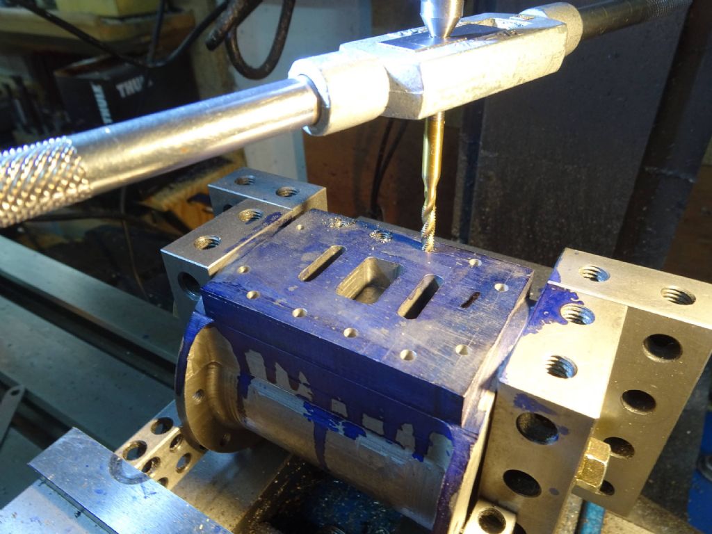
Mounted the cylinder in the milling machine. The basic idea was to put the cylinder on the valve face and bolt some 2 4 8 blocks to it and then use the 2 4 8 blocks to mount in the vice. I'd tried this before for some operation, but there was a bit of wiggle.
By dint of some 2 4 8 blocks, some wooden chocks and surface plate I was able to establish that the bottom face was pretty much at right angles to the bore of the cylinder and the top one a bit off. This was not surprising (and to an extent expected) as I'd done the base and bore in one operation and the top after turning and remounting.
So I bolted the cylinder to the mill table and took a light facing cut.
Then assemble the fixture, mount in the vice and centre drill, drill and tap the chest holes.
And lo and behold, it fits together!
Any ideas on the steam gland would be gratefully received by the way. It turns out that the chest fits slightly better on the cylinder with the would be eccentric hole at the top, so I have another good (?) excuse to turn the chest round and mount a gland on what will now be the bottom.
Iain
31 May 2021 at 19:04 #547942 JasonBModerator@jasonb4 June 2021 at 20:07 #548345
Iain Downs
Participant@iaindowns78295I should learn patience.
Many thanks for your advice (as always, Jason). In this case, I'm afraid I jumped a little too soon as I liked the idea.
I've already drilled and bored the other end and will eventually make a gland to bolt on. What I DID get however, was JB Weld. Something I've not really had contact with. I will use that to secure the pin in the end I don't want.
But for all that, this has been a good week! With the valve chest done (and drilled), I was able to put the beast together for the first time
 .
.And, yes, Jason, my workshop is ALWAYS that messy…
 .
.The remaining items are some support brackets (for the eccentric rod and the cross head slide), the chest cover and the valve gear control handle.
Oh and seeing if 3 years of pain have paid off in something that at least kind of works!
Iain
2 July 2021 at 12:36 #552258Iain Downs
Participant@iaindowns78295I suppose the starting point is to admit that Jason was right and I was wrong (hard to imagine how that could ever be!)
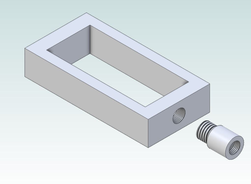
Having looked at the valve chest I couldn't see any way my idea would work, so I tapped an M12 in the end and made a gland to fit in it. Pride goeth…
and here's a shot of the gland nut being made – putting a hex on the end of the nut.
One 'interesting' thing about the gland nut is that I happened to have a bit of sliver steel the right length and diameter so tried to cut that. I went through most of my tooling before I settled on a (steel) carbide insert which did the job. I burnt the tip of an hss home ground tool, smashed the tip of an aluminium insert and had some success with a brazed carbide tool facing, but it really didn't like to turn the diameter down. Of the lot, the carbide insert that worked seemed the least sharp! Oddly the thread cut easily (with a die).
However, what has given me the most pain since the last post is the eccentric guide. It's taken me 3 goes
 .
.The first attempt wasn't too bad, but I'd not taken into account that I'd shifted some dimensions to deal with a 1.5mm offset of the support struts from the main bearings, so the shafts weren't symmetrical around the bore. I'd forgotten (two lessons- one don't get it wrong early on and two – don't take several years to make something – you will have forgotten what you did wrong!).
The result was that I couldn't quite set the guide plate in place.
I'd done the first try clamped to the mill bed on a sacrificial plate, but that meant the quill was full extended and nasty singing noises happened.
I decided to buy some thin parallels so I could mount it in the vice. They arrived, but time passed and I'd forgotten about them before I came for my second try. I'd be less embarrassed if the time in question was months rather than weeks (or less
 )
)I'm not sure what happened but the forensic evidence is that the clamps slipped – the piece was pulled off centre and too; my only 4mm 2 flute cutter with a long cutting area with it.
Finally, I ordered some 4mm carbide 2 flute cutters, remembered the thin parallels and made my third and final attempt.
I have two more main bits to make (plus gaskets). The support strut for the cross head guide and the steam chest lid.
I've also got to work out how to control the stephenson reversing gear. I think I just need a longish arm that secures the gear and can be moved left to right by a lever. Longish to keep the left right movement of the gear to a minimum by minimising the angle of movement. I think.
The end is in sight!
One question I will be asking shortly (which in this build terms is probably about 3 months) is how to set the valve timing. Let me wait until then though.
Thanks for the advice Jason!!
Iain
20 September 2021 at 20:37 #563616Iain Downs
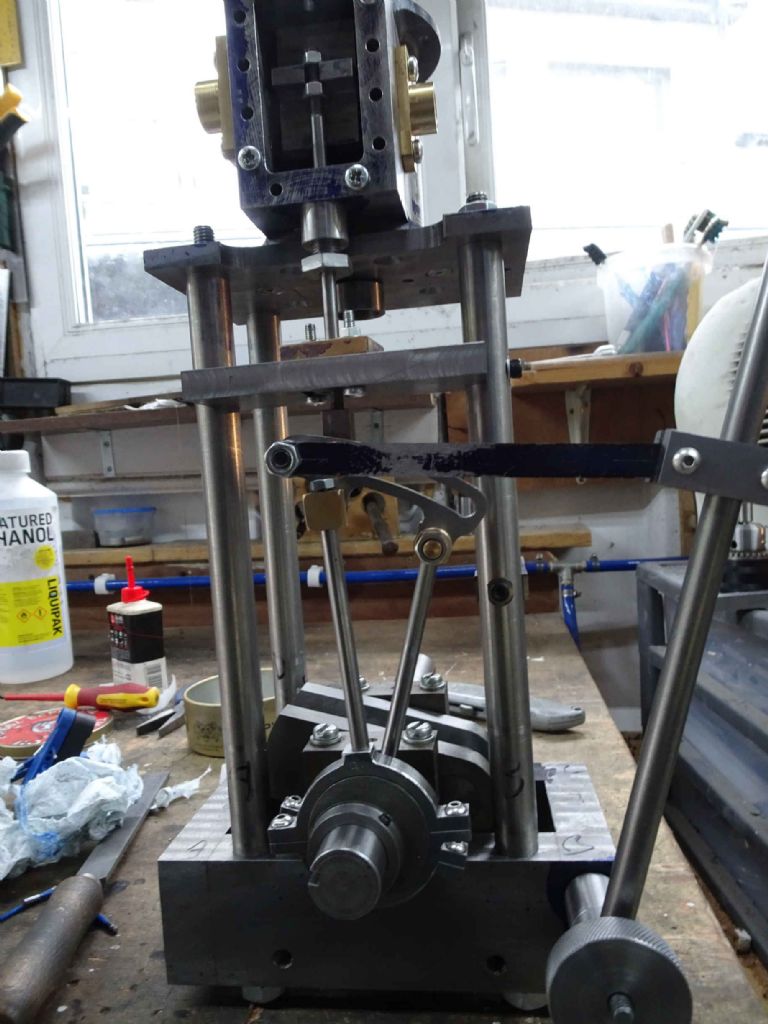
Participant@iaindowns78295To mount the items above I milled some flats on the sides of the support pillars
And the spotted and drilled through.
Notice that the pillar sticks out a long way. I was worried that there would be too much movement, but the engineers jack seemed to work nicely.
Oddly, the closer I get to the end of this journey the more likely I am to sketch (on paper) and hack away rather than go back to my CAD model. At least some of that is because the CAD model is now rather complicated and messy and I suspect my dreams of a data driven parametric model have been lost in the noise of minor changes. Ah well.
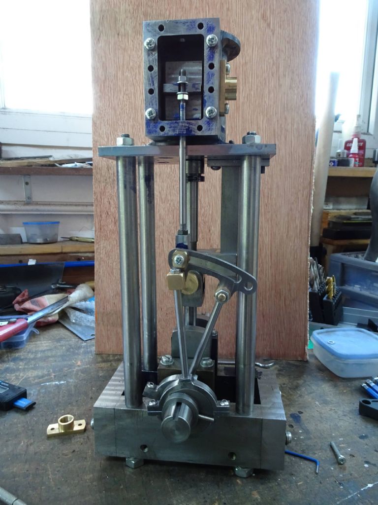
And here, at last is the majority of the beadt.
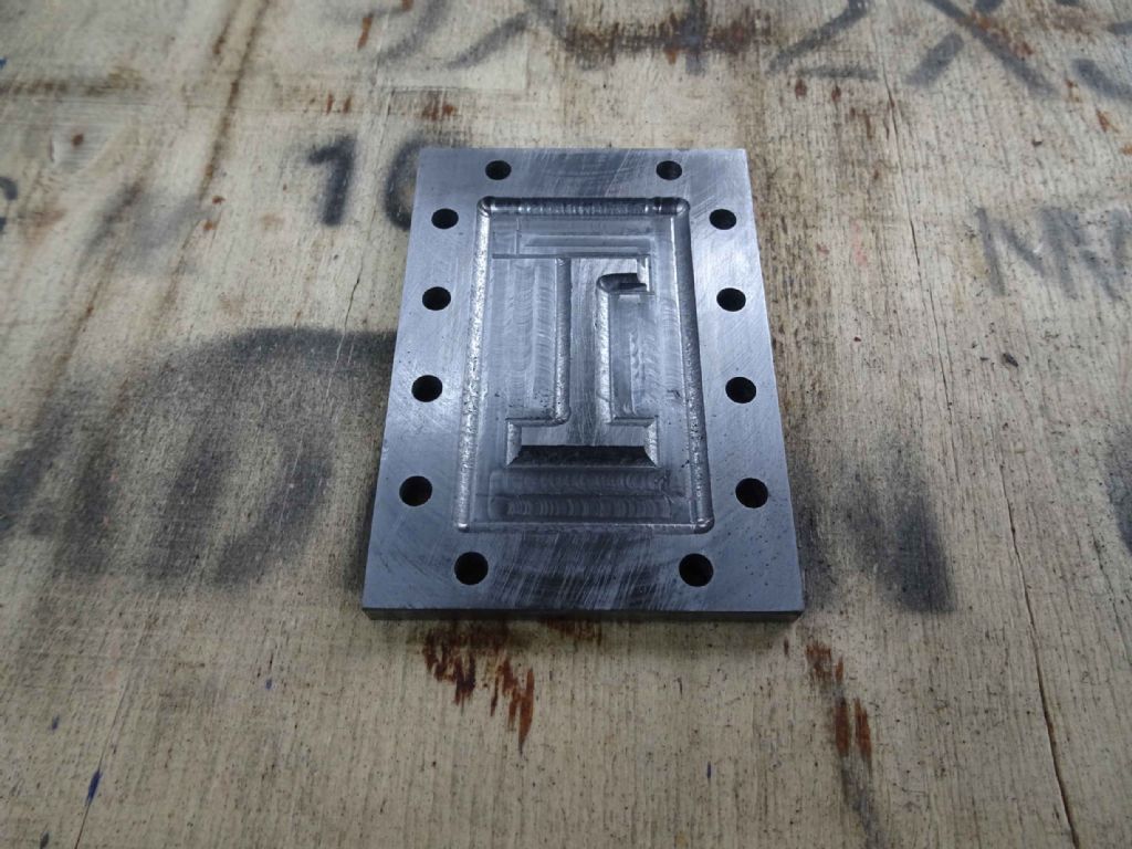
At this point the only part I need to make is the valve chest cover, which I have since done…
The sceptical reader may recall that my name (Iain) starts with a capital I and may suffer from the misapprehension that the 1 (one) symbol is, in fact an error in manufacture. Not true of course.
It needs tidying up a bit (and I may recut it, now I realise an I (eye) is would have worked better!)

Iain
20 September 2021 at 20:53 #563618Iain Downs
Participant@iaindowns78295What TWO postings in one day!!!
This is a gasket cutting post.
I was much inspired by a couple of articles in MEW recently and also a hint from Joe Pie in his recent model steam engine build.
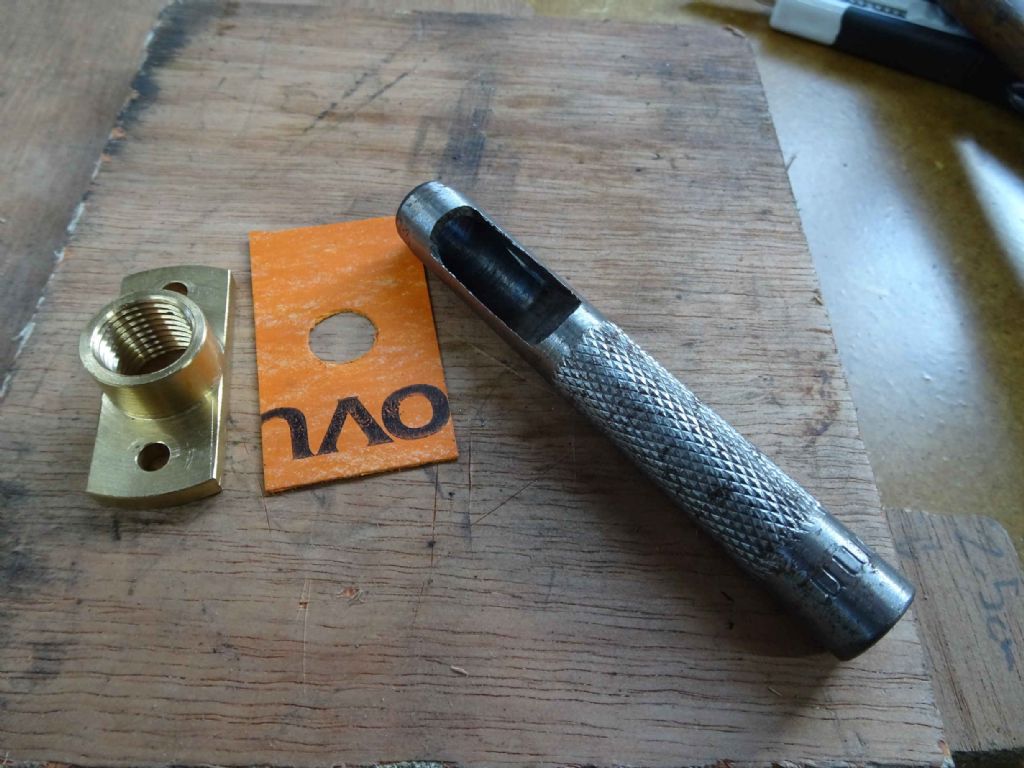
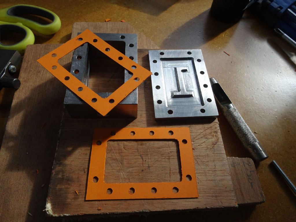
I had 3 sets to build. First gaskets for the steam inlet and outlet ports (brass in the previous picture).
I found I had a leather punch with a hole about right for the steam hole, so I started by punching a hole in some gasket material. next I mounted the port over the hole and carefully trimmed round the edge with a craft knife.
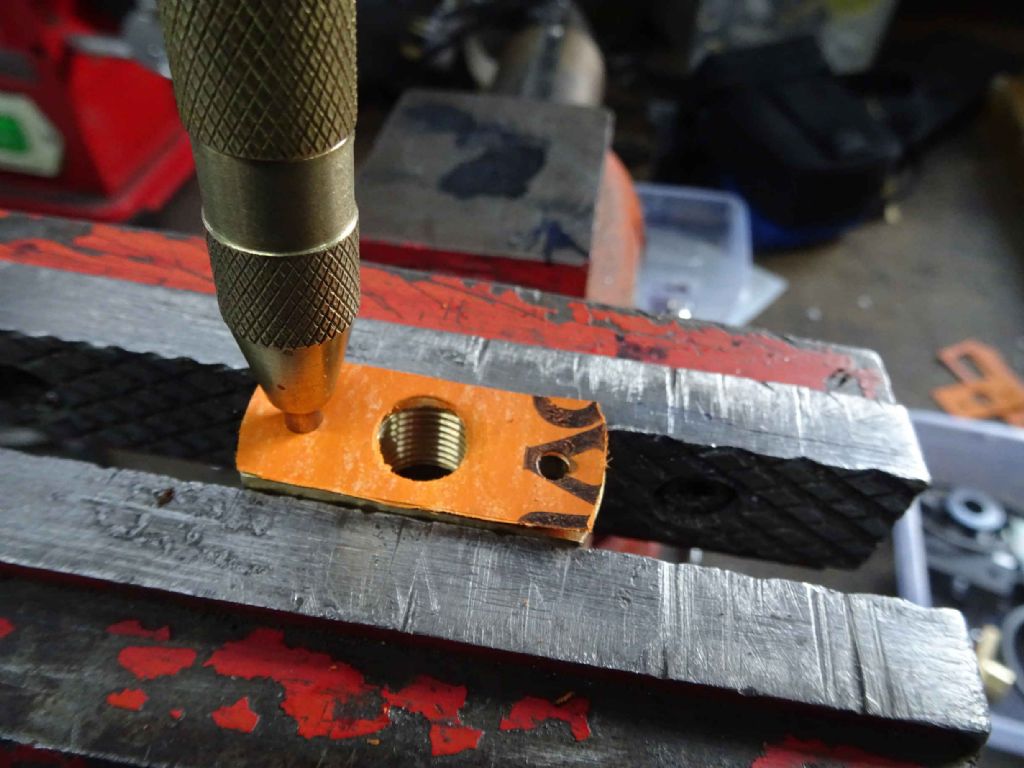
next I mounted the port upside down in the vice and put the gasket material over it. Then knocked out the bolt holes with an automatic centre punch.
That went reasonably well. I think I only ruined one or two.
Next for the steam chest. I needed two here one for the top and one for the bottom.
I started by slicing round the steam chest for both pieces in one go.
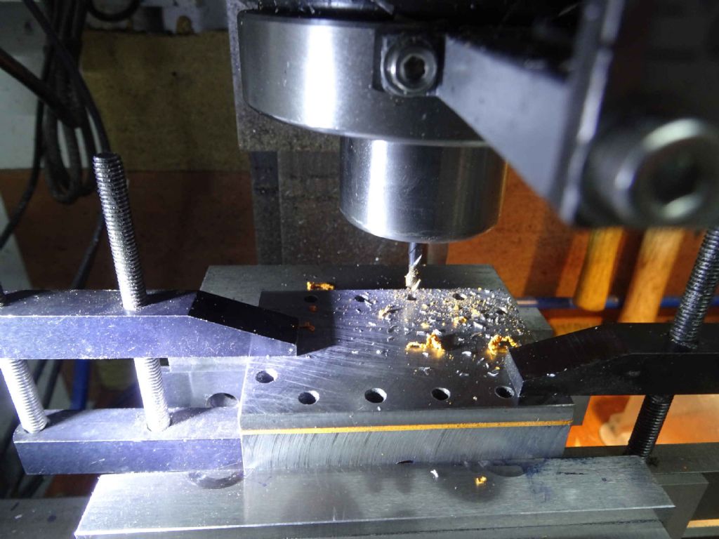
Then I clamped the chest walls and top with the gaskets between them and carefully drilled through with a 4mm end mill.
I'd had a previous go at cutting out the centre on a surface with just the chest walls, but this just resulted in a mess.
I also found later that I could have just put the end mill in a spare chuck and done it by hand.
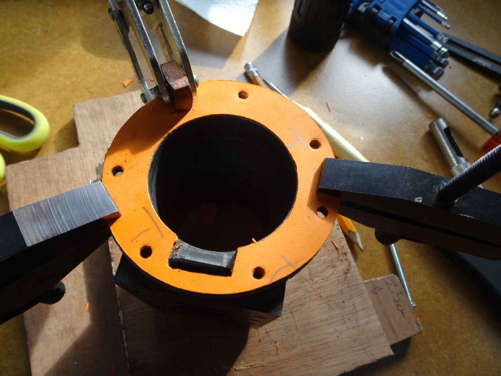
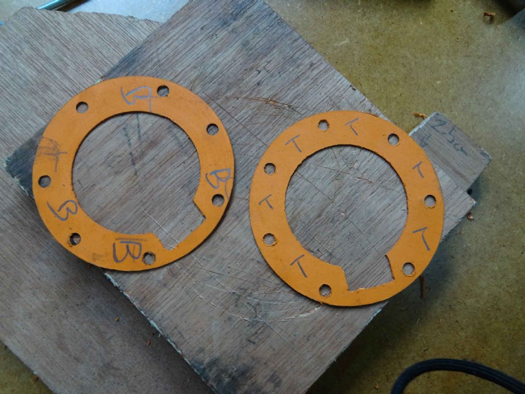
The cylinder end caskets were more tricky. This is mainly because I kept getting the end wrong. Despite what you may think would be ideal, the two cylinder ends are NOT quote the same. One a fraction wider and they seem to have subtly different hole patterns. A couple of bits of gasket material went in the bin there, as well.
So I started by placing the cylinder on the gasket material. then careful cut round, except where the valve chest stuck out. Then rotated the cylinder 180 and lined up on the cut circle then cut the rest.
Turn the cylinder upside down and clamp the material to it in 3 places.
Cut the inside out with a craft knife and then punched through the mounting holes with an automatic punch. I actually found this could leave a bit of a ragged edge so I tidied up with a 4mm reamer followed by a 5mm reamer (the bolt circles are 5mm).
I'm quite pleased with how these ended up.
Iain
20 September 2021 at 21:05 #563619Iain Downs
Participant@iaindowns78295Now what questions
So I have all the parts made, nearly 3 years on.
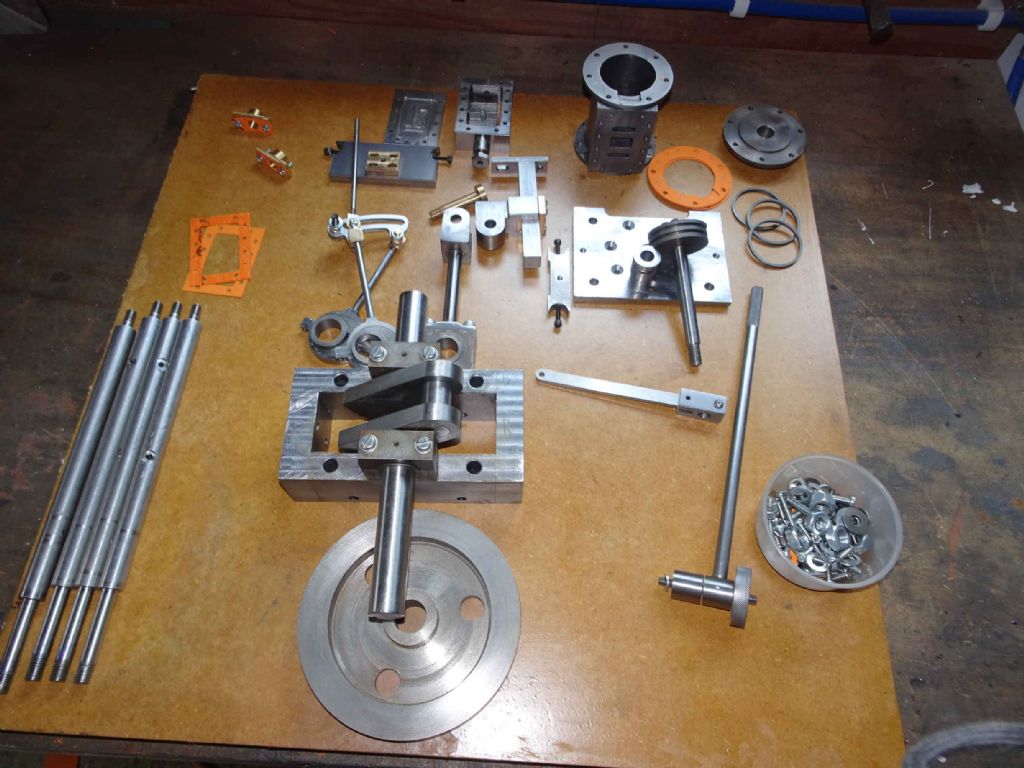
I need to scrape the big end bearing and I want to do a bit more on the main bearings.
I want to lap the face of the valve chest and D Valve.
I haven't put any balance on the crankshaft, though I can refer back to some articles on that in ME or MEW. I don't know important that is in practice, bit I expect I should do something.
I've only trial fitted things so far. There's a good bit of fixing a thread sealant for when I finally decide to put things together.
I don't know how to tune up the engine. I know that I need to balance the D Valve so that it exposes the same amount of valve port on the up and the down.
What I don't know is how to set the timing. the engine is roughly based on A Stuart 5A, certainly in terms of the valve timing (though converted roughly to metric).
Any help on that (or pointers) would be much appreciated).
Iain
10 October 2021 at 18:34 #566305Iain Downs
Participant@iaindowns78295First off, for any reading this thread, I found a very useful video on setting timing by Keith Appleton which you will find here.
All the parts made? Well. actually all made (except one bracket – I think), but still some finishing off needed.
Here are the parts
I still had to finish off the bottom cylinder plate and mount the piston guide (originally my thought was silver solder, but laziness makes me consider JB Weld. Terrible of me). More of that below. I also need to split the piston rings – that one does worry me, despite having a brief tutorial from Richard Gibbons at the start of my adventure. Oh and put a keyway in the flywheel.
First though was doing a bit more scraping of rhe bearings. For some reasons I got quite good results with the lower main bearings, but didn't seem to get some a level of blueing on the upper shells. I got somewhere with it and moved on. the big end bearing, I scraped until I had a nice free running fit without worrying too much about points per inch. Slack, again.
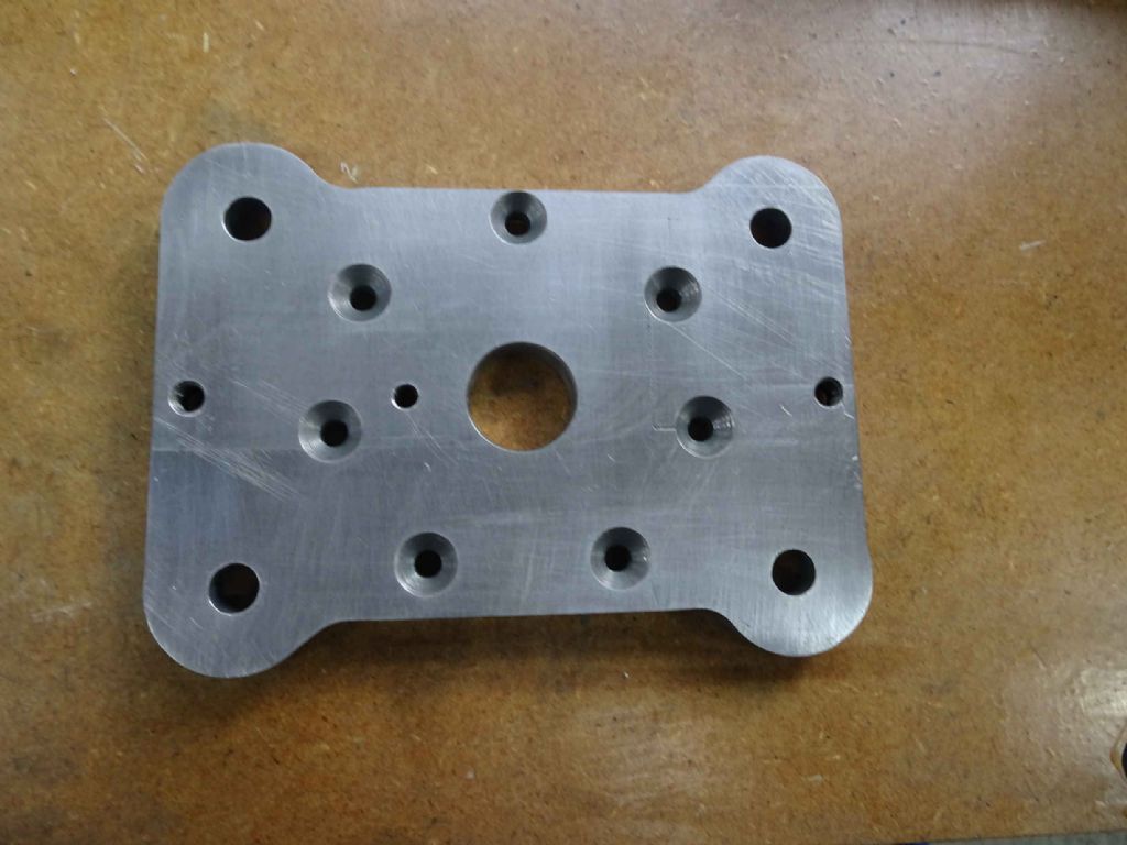
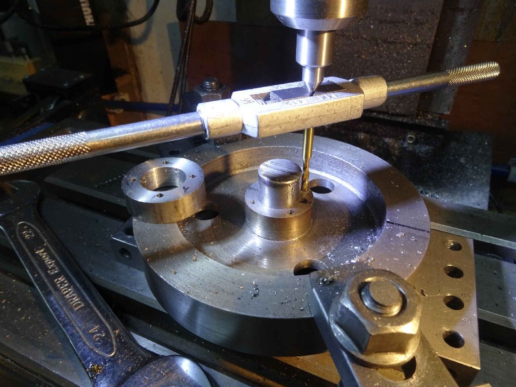
Next was finishing off the bottom cylinder plate which was mainly about milling an inset and then some nice clean circles round the support holes.
As so often, I got to the end having realised I started in the wrong place. The work on the circles round the support holes clearly needed the rotary table so I lugged that up onto the mill. Either it's got heavier in the last year or a year of working from home as sapped my strength! Phew!
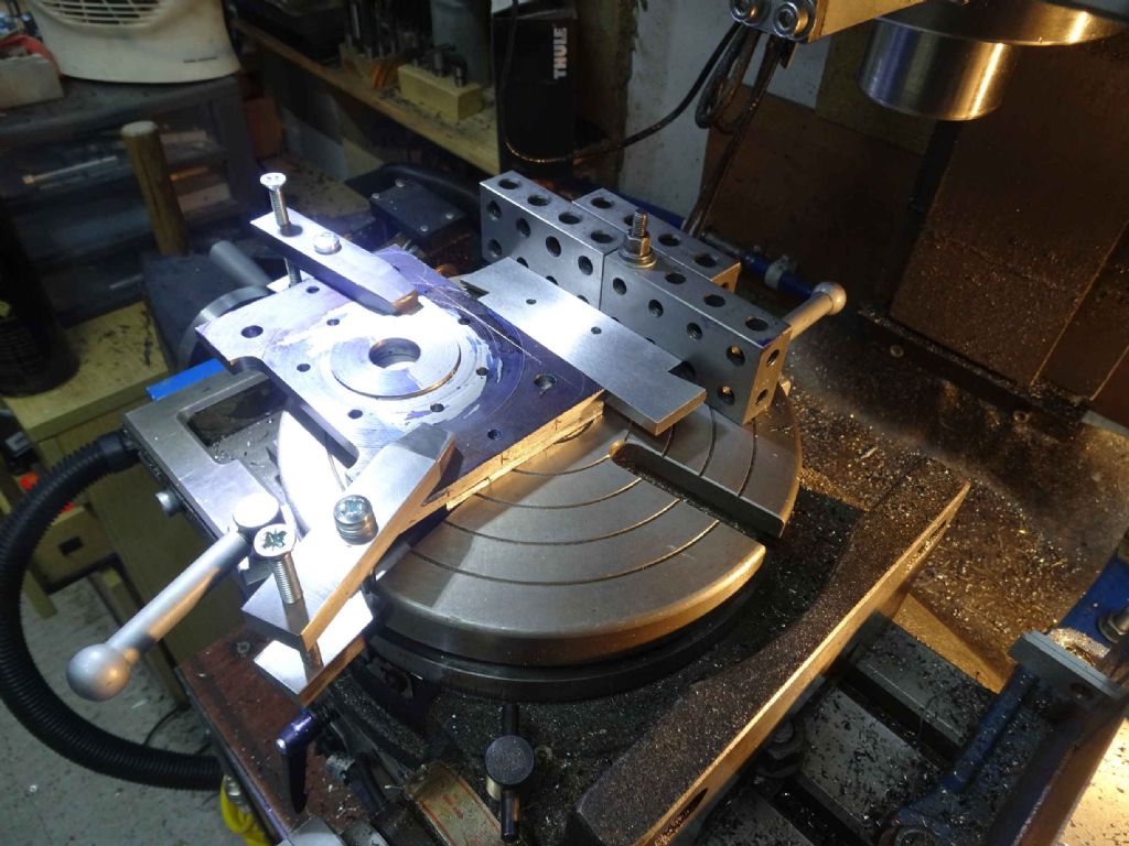
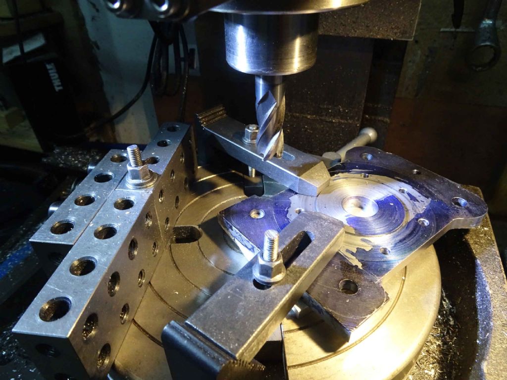
I spent some time working out how to ensure that the edge was aligned – requiring (so I thought) to make some engineers clamps which fitted the table.
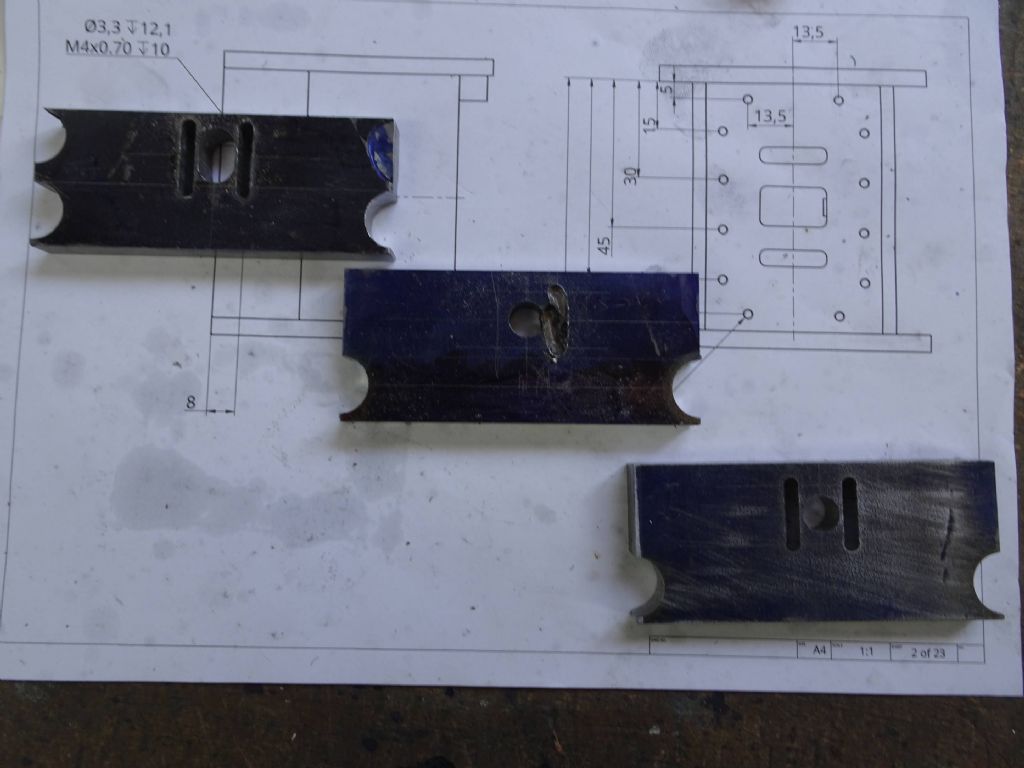
The 1 2 3 blocks on the edge were indicated aligned with the X axis an adjustable parallel used to align the piece. You can see the clamps – made so that the lower part fits in the T slot.
The end result of this manufacturing and set up effort was that I milled a flat inset by eye along the edge of the piece. Frankly, I would have been better of doing this in the vice.
I realised this later after understanding that that was the only operation that actually required parallelism with the axis. For the corners I realised that would be better off moving the piece around so it could be clamped more easily and so I did.
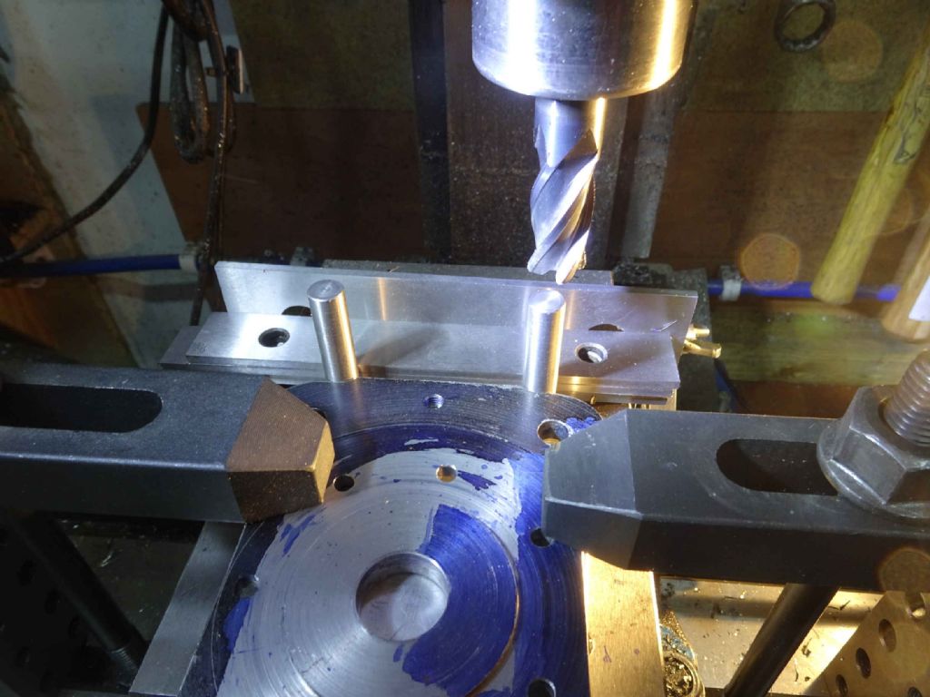
The support holes on this were not 100% as one might desire. I can't recall now which of my many errors led to this, but I decided I would take indent the short ends a little and then somehow across the flats to join the recesses.
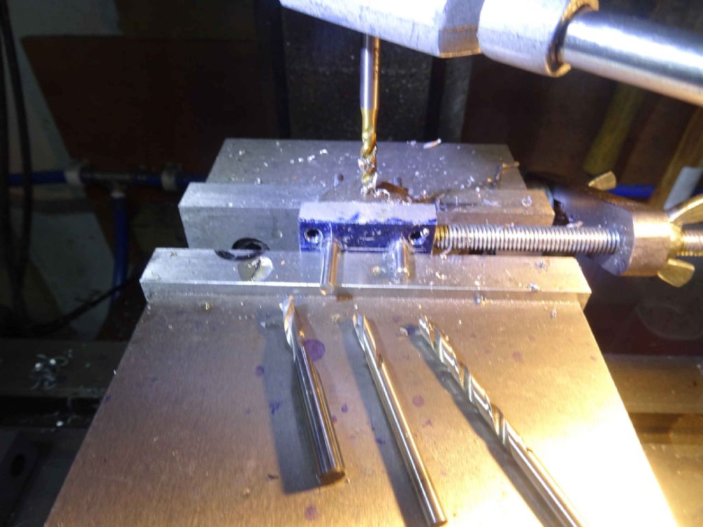
I had a few goes at how to set this up and came up with the above. There is a parallel clamped in the vice jaws. In from of that a couple of short parallels as packing and then some wider ones at the top. in the milled recesses I put two pins (sadly, I like the thousands of super accurate pins available to some Youtubers and mine are just sliver steel with a very minimal set of size ranges!). Push up the plate to the pins, settling them in place and then clamp.
If I was doing it again I would try and get the side to be milled to face forward so I could see better what was going on.
In the end it worked well enough and here is the finished plate.
One thing which I have yet to learn is the fine art of removing machining marks. My patience and emery paper don't seem to be a good combination. My dremel tools seem to strong or too weak. I have mind you just ordered some sanding belts in a variety of grains for my dirt cheap Chinese belt sander. Perhaps they will help.
Next the flywheel keyway and then the piston ring splitting…
Iain
7 November 2021 at 16:55 #570320Iain Downs
Participant@iaindowns78295When I made my flywheel I'd not quite thought through how I would mount it on the crank. I mean, I know enough to put a keyway in the crank, but there the inspiration stopped.
I could have bought a 2 inch wide piece of cast iron and trimmed back to an inch bar the collar, but that was clearly just a silly idea.
What I've ended up doing is putting a keyway in the flywheel and making a collar to attach to the flywheel.
First was to make a keyway cutter – 4mm wide.
This ended up being somewhat of an epic. I did it using the 'square hole' approach in a recent (I think) Tubal Cain video. Which is to say cut a slot, glue something on top of it and the remove the surplus in a lathe.
The main problem, however is the tool bit material and the gauge plat I'd got which were meant to be 4mm were both a bit over. By the time I'd trimmed down the HSS toolbit, I'd gone too far, though I had a bash anyway.
Here I am centring the flywheel and here is some cutting.
This actually worked quite well, but the cutter was just a bit too narrow and the keyway not quite deep enough (I can't explain the last aspect given as I was using a DRO).
So I made the cutter again, re-centred the flywheel and had another go.
that worked quite well.
Next the collar.
7 November 2021 at 17:20 #570321Iain Downs
Participant@iaindowns78295Next the collar.
The idea here was to make a bit with the same bore and external diameter bold it to the end of the stub in the centre and hold it with some grubscrews.
First to chuck up a piece of 30mm mild steel face it and bore it to size. Checked this with a bore gauge and a try fit with some 22mm silver steel from the same stock as the crank. Turned it round and face the other end.
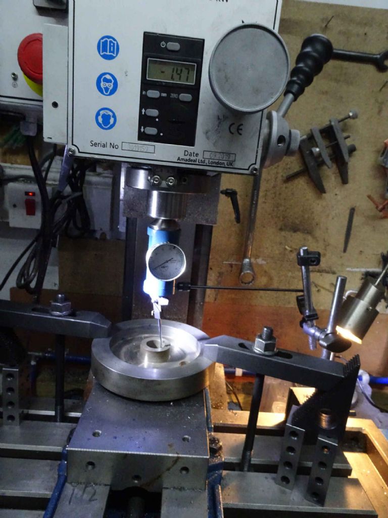
Next, put the flywheel on the mill, the same piece of silver steel in the centre and clock it under the quill. I've recently got a quill mount for indicators as the big boys (Stefan and Joe) seem to think this is a good way to do things. At a tenner the quill mounted thing isn't bad. However, the cheap as chips indicator I just bought is less good. My Christmas could feature a mitutoyo or similar.
Nonetheless I got it centred within a thou or two. Actually, I'd not checked the width of the heads on the allen key bolts and I might have gone with M3 rather than M4 as they needed just a little bit of fettling once fitted.
Drilled through the collar into the flywheel centre, then removed the collar drilled and tapped. Seems to work!
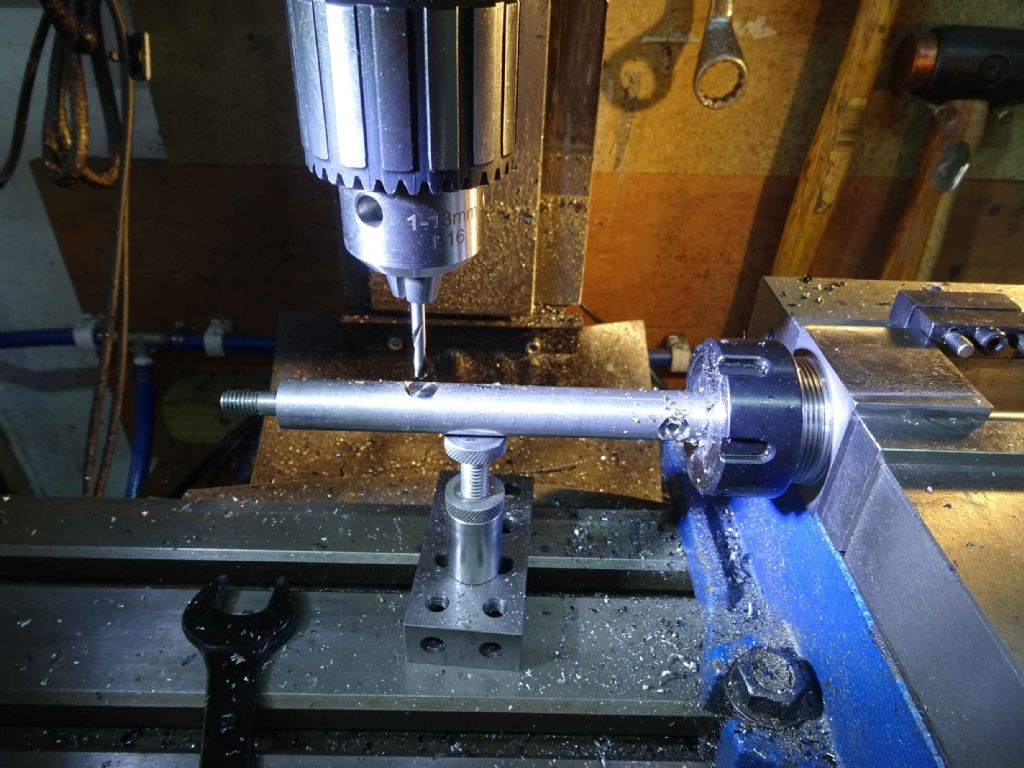
next stop was to put the holes in for the grub screws. This took a bit of thought, but I ended up finding a piece of scrap aluminium which was square (more or less) and about the size of the collar. Drilled 4 holes to match the collar and then used some pins to align it on top of the vice.

4mm 2 flute end mill (I know not in a drill chuck, but I was just flattening the top). 4mm spotting drill to centre (I'm a spotting drill boy on the mill, but centre drill on the lathe. Don't really know why, it it seems to work OK). finally tap drill then tap.
Turn the collar over, replace the pins and to the other side. I've ended up putting 2 grub screws in at 90 degrees to the keyway.
I spent some mental effort working out how to then trim this down to size. Or more accurately, how to hold the flywheel accurately.
My first thought was to hold it in the 4 jaw and centre it. However, I needed to hold the thin side and it soon became clear that holding onto a 4mm deep recess with the 4 jaw and getting it centred was a mugs game. Just not enough to hold on to . I occurred to me later (just now, actually), that I could have supported it with a revolving centre, but probably would not have held on anyway.
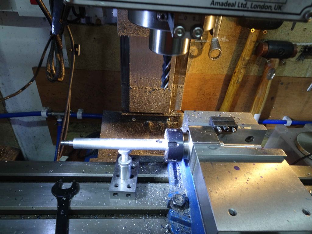
Instead I made a mandrel. I chucked up another piece of 30mm mild, faced and then drilled and tapped to M6. The idea was to bolt the flywheel and collar onto the mandrill.
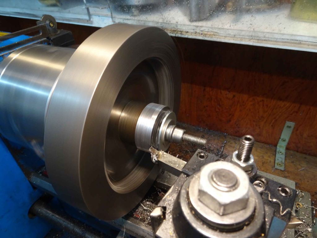
The turn down the outside of the mandril down to a tight fit for the flywheel, push it on and bolt it down.
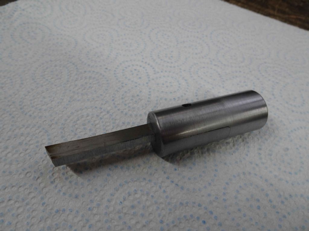
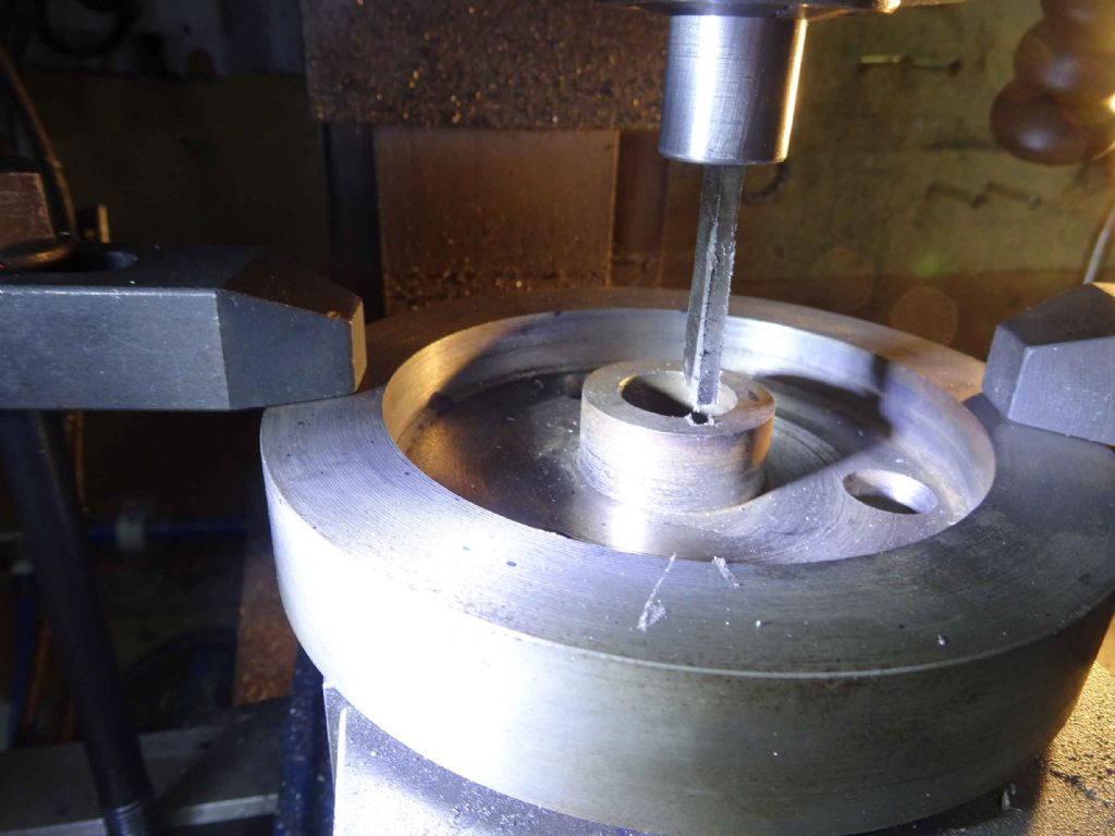
The tool appears to be a trepanning tool I made a while back and I could have probably done with something a bit more rigid, but it got the job done.
Whist I was at it, I attempted (unsuccessfully) to shine up the stop and the outside (with a bit more success).
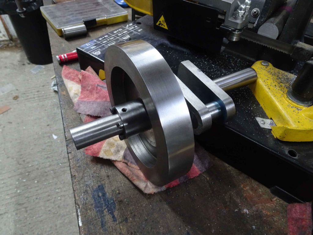
And here we have a flywheel on the crank secured with a key and held in place with collar and grub screw.
Oh – and here's my question of the day. Should I harden and temper the key or will it be OK as it is?
Iain
21 November 2021 at 17:19 #572327Iain Downs
Participant@iaindowns78295The marathon continues!
Today's episode was all about heat. Two successes and one abject failure.
I wanted to
- Finish off the piston rings
- Heat treat the flywheel key
- Silver solder the piston gland to the bottom cylinder plate
The first thing I found was that the piston rings didn't fit the grooves in the piston. Either I cocked it up or didn't check a couple of years back (see Page 7 of this epic) when I made them or they've grown in the intervening time. Take your pick…
One appeared to fit in the grove and also fit down the cylinder. The other two not so much.
First task was to thin down the ones that were too wide. 30 mins or so with some wet and dry got me there. Probably should have started off with something a bit coarser, but there you go. A this point when I tried it, I noticed that the groove didn't seem as deep as the rings. Indeed. One was 2 mm and one a tad under 2.5. So I put the piston (it's been on the piston rod for a while now) in a collet and dug the grooves a bit deeper. I had to go very carefully here as the parting tool (carbide) would jam fairly easily.
But I got there (no pictures of that, I'm afraid). I suspect that this opened up the grooves slightly as well, as the 3 rings fit better.
A few more minutes breaking the edges (probably another reason why they weren't entirely fitting) and the three looked good.
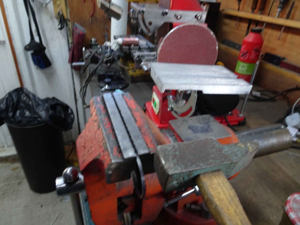
Now for the scary parts. First to break the rings.
This is a posed picture of course. I wasn't going to try this delicate act whilst holding a camera in my other hand.
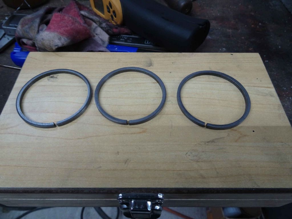
Somewhat to my surprise, all three rings broke fairly cleanly (and not in two!).
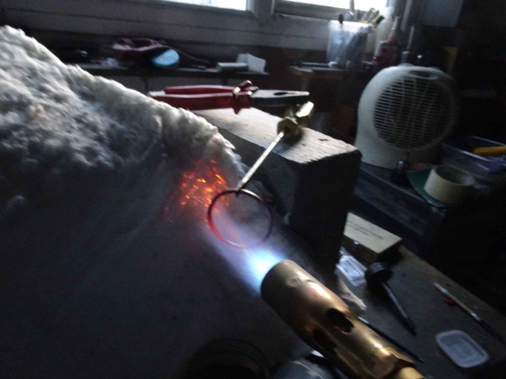
Next tidied up the broken ends with a diamond file and on to the other scary bit, the widening.
I expect there are better ways. I'd seen something like this on you tube and expected the ring to just drop off the screwdriver into the oil poised below it. Needless to say it didn't, so I had a fine time trying to knock it off with another screwdriver whilst attempting to hold the screwdriver it was mounted on steady with the torch hand.
Had one that got away (on the floor!), but no damage was done and simply re-heated and next time dropped it in OK.
One spare to break when fitting on the piston. Gap is a little over 2mm. struggled a bit to do this scientifically as I could no longer find the articles which provided the calculation, but I don't think I want or need much of a spring.
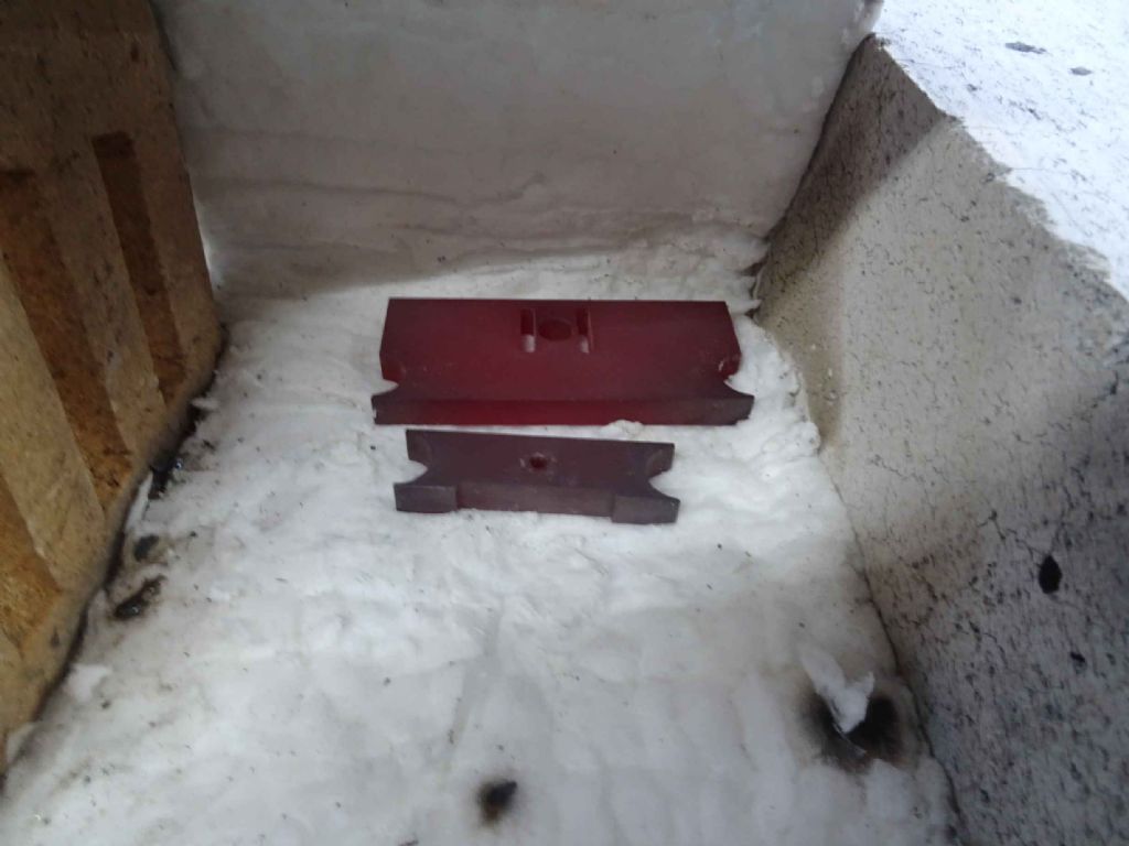
Next was the key. Made a cage and smothered it in boric acid, heated to dull red and then dropped it in the oil. Seemed to work OK. File made the right sort of skittering noise.
Not much oxide on it due to the boric acid, but shined it up and tempered it. Well. Differential tempering as it turned out. One part straw, one nearer to blue. Still, I imagine it will do.
The last item on the list was silver soldering the piston gland to the bottom plate (which can be seen a few posts up). This just didn't work. The flux was gone early and the plate never got hot enough to melt the solder.
Me and silver soldering have yet to have a success and it's so long since I last tried I'm not even sure I'm using the right flux and solder.
So I expect I will buy something known from Cup Alloys and try again (I'll do some practice first). If that fails, I will hang my head in shame and resort to JB weld.
Nearly there. However, the advent of winter my further slow down what has been a glacial build. Today was about as cold as it gets (5 degrees or so) when I can realistically get in the shed. Mind you if it's the soldering, I could make an exception!
Iain
21 November 2021 at 18:07 #572330Iain Downs
Participant@iaindowns78295It turns out I have a question.
Gland packing. The two options I can see from a search of the forum are PTFE tape or (Jason's recommendation) graphite twist packing Sadly, the link for the latter doesn't seem to go to anything which is purchasable.
Is this the same sort of thing? I have a feeling that square isn't great and 3mm may be a bit big for my model. Not sure if it compresses.
If I go for PTFE is that just the plumbing tape or is it something more specialised?
Many thanks.
Iain
21 November 2021 at 18:09 #572332 JasonBModerator@jasonb
I would have expected a bigger gap on what I seem to remember is a 2" bore, something in the region of 0.250-0.312" and there is no real need to drop them in anything, just let them cool naturally. But give them a try, you can always reheat with a bigger spacer if they don't seal well.
21 November 2021 at 18:26 #572333 JasonBModerator@jasonb
EKP's gland packing will be quite close to the one Heritage used to do.
21 November 2021 at 19:58 #572343Iain Downs
Participant@iaindowns78295They're already quite tight in the bore, so I hope it will be OK. And thanks for the link. I have ordered

Iain
20 December 2021 at 15:16 #576028Iain Downs
Participant@iaindowns78295Day by day, ever closer comes the time when I can put this thing together and see if it works. I am fairly determined to have it built and ready to
steamair up by the end of the year! Yes, in two weeks I will stop yammering on about my engineering weaknesses in this thread. Some assumption here that I can get to my Shed and it's not TOO cold… :
Mind you I have another project in mind to start which will expose still more about my lack of skills. Ideally, whilst taking less than the 3 years + that this has taken.
So what have I been doing? Finishing off (as I call it).
I realised that my cross supports (one supports the eccentric rod and one the bottom end of the cross head guide, were a bit rough, being formed from cold rolled. So I thought I would smooth them off. It's kind of like taking pride in my workmanship as long as it's not too hard (which you will find a theme in this post).
Anyway, I've read about how cold rolled can turn into a banana if you skim one side of it, so I warmed both up to cherry red and let them rest for a bit. Then in the mill an skimmed with a face mill. Seems to have worked.
The other thing I've been expecting to do for quite some time is to rework the cross head bearing. Basically, I messed the manufacture of this. The holes were around 10.2 mm with the axle being about 10. Thus it rattled. I'm not entirely sure how bad this is for a bearing, but my guess was – not very good…
So I opened out the holes and then made a 12mm pin for the axle.
This is me finding a way to hold the part in a useful way.
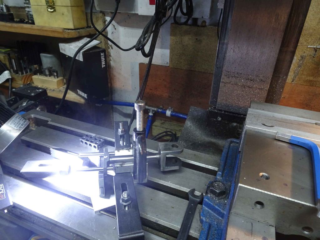
Not my best photo (and my best aren't that good!), but what you have here is the big end rod clamped in a V block with an adjustable parallel under the big end bearing mount, setting it square with the bed. This should set the axis of the cross head bearing 90 degrees of the big end. Which is a good thing.
I centred on the current holes and then took a first cut with an 11mm end mill, then a 11.5mm drill then finished with a 12mm reamer. The idea was that if I was a bit off with the centring the 11 mm end mill would still cut a nice clean hole for the larger tools.
Cross head proper was a bit easier, – just clamped in the vice and again 1mm end mill, 11.5 mm drill and a 12mm reamer.
Finally a bronze bearing 12mm in diameter and it no longer rattles but does turn freely.
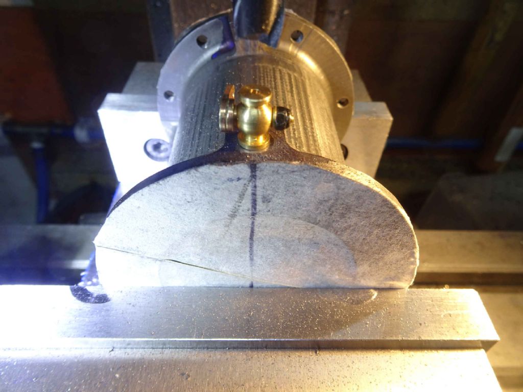
One thing that I've left for a long while is some drain cocks on the cylinder. It looks unlikely that this will ever run on steam, but if it ever does, I will need this. I can tell you how long I've been planning this – I bought the cocks and taps at a live ME show! Yes, THAT far back!
The only interesting part here was drawing a diameter in line with the cock location and then ensuring it was vertical with a square in the vice.
A bit more, but I will add this as another post.
Iain
20 December 2021 at 15:39 #576030Iain Downs
Participant@iaindowns78295My last post today starts with a confession of failure.
Both my lower cylinder plate and my steam chest needed bits attached to them. I've had a go at silver soldering the bottom cylinder plate, but was unable to get it hot enough, or there wasn't enough flux or I'd picked up the wrong type. Or something.
I have rebought some known flux and solder and intended to practice on a few bits and then do the job. In the end I couldn't be arsed. I have to finish this damned thing some time. So I got some JB Weld and I've gummed the bits together with that. Feels a bit wrong, but what can you do? Silver soldering practice in the New Year!
My other, hmm, challenge, has been the real finishing off part of finishing off. Polishing and painting. My idea was that some bits would be shiny and bright and the rest black.
I started off by attempting to polish the 4 uprights. They are 16mm stainless about 200 mm long. Essentially they are a 200 mm bar with a 10mm diameter projection at one end and 6mm at the other, both threaded as needed for mounting.
I held the 10mm dia piece in a collet in the lathe and ran through various grades of wet and dry, followed by some polishing compound.
The results are a little mixed. All are shiny, but on some I've not been able to get the surfaces smooth as a mirror. Less scratches and more lots of very tiny pits. I have no idea if that is the type of metal, the nature of the abrasive or the cack handed nature of the operator. You will inevitably have your own opinion….
One thing I did notice is that some cheap and cheerful sets of wet and dry (bought in bulk from one of the usual places), left a cloudy finish on the piece, whereas some stuff I've had hanging around for ever which has a lower grain (2000 and 1500 respectively) left it lovely and shiny.
Finally, I've moved on to painting. Another delicate skill for which I have little talent. I'd decided a needed to use a heatproof paint around the cylinder and should use the same paint elsewhere to have a consistent colour.
The long and short of it is that the paint has gone on reasonably well, but if I look at it wrong, it chips off. I'd cleaned everything in alcohol and work latex gloves – I've never been so clean! I bought something called 'Rust-Oleum AE0020001E8 400ml Stove & BBQ Paint Black' on the grounds that it had the least bad reviews.
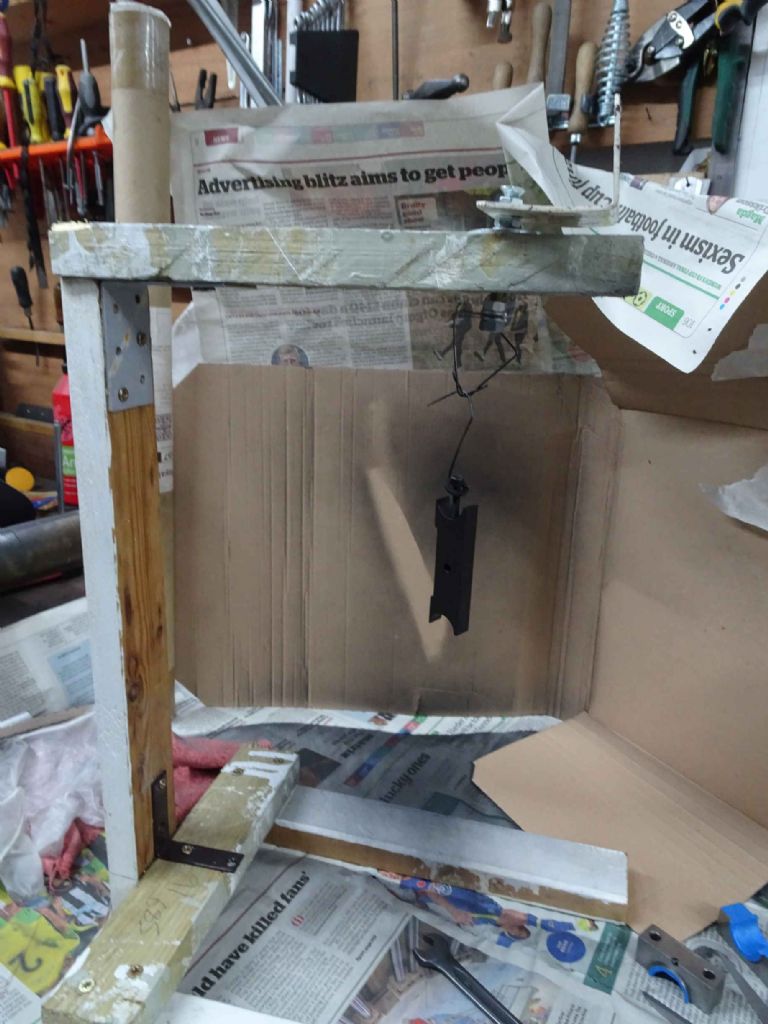
I made a little scaffold with a turntable so I could hang the smaller pieces and rotate them as I applied lots of very thin coats (which, mainly, I managed to do).
Mr Robinson (Heath) would have been proud.
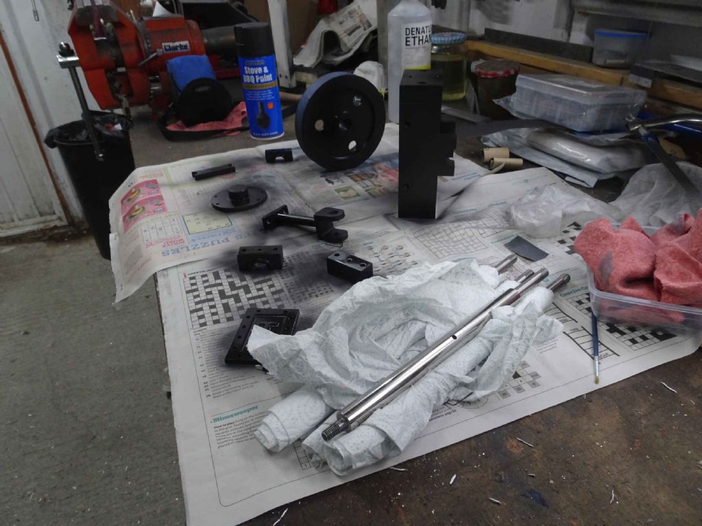
So at this point, most parts have had several coat – bearing surfaces masked of course, and I'm expecting a mess when I peel the masking tape off – and as implied earlier, this is as good as it's going to get. If it comes off, it comes off.
Here you can see work in progress. Black base, flywheel, bearings and so on. There's more to do, but I'm waiting for the JB weld to dry (and have probably run out of paint)
Perhaps in 10 years time when I've recovered (or gained some skills), I will repaint.
I'm leaving the eccentrics as they are and still have a bit of polishing for rods to do, but it's nearly nearly nearly at the point where i can put it together, apply some air and …. Who knows?!
Iain
20 December 2021 at 17:39 #576048 Alan JacksonParticipant@alanjackson47790
Hi Ian,
I have just read through your trials and tribulations of this build. I have to congratulate you on your write ups they are very honest and amusing, and they show how you are gradually but surely progressing and improving in your skills.
I hope your engine runs smoothly and returns you great satisfaction. Thanks for your writings and Happy Christmas.
Alan
Edited By Alan Jackson on 20/12/2021 17:42:01
20 December 2021 at 18:24 #576054 JasonBModerator@jasonb
Getting closer

The surface finish of the stainless may be due to going at it straight away with W&D, something with a bit more cutting power to start with would have taken down the original surface to remove the pits and only then should you start working with the next grit. I seldom go below 150g emery which gives a bright but not mirror finish that I find pleasing.
Check what it says on the tin, quite a few stove, BBQ and VHT paints are not very durable until they have had a couple of heat cycles, you may need to slip the parts into the oven behind the Turkey when no one is looking.
20 December 2021 at 22:38 #576093Nigel Graham 2
Participant@nigelgraham2Fine work, Ian, and very interesting commentary.
Regarding the finish on bright steel engine parts, all the full-size ones I've seen normally have a lovely satin sheen, which is partly original good-quality finish and partly from years of cleaning with an oily rag!
Certain parts can be appropriately finished by careful draw-filing.
One of your posts asks about heat-treating keys. I would not do so, since on a small machine like this it is carrying such loads it won't be anywhere near shearing.
I had to make a key recently with one half (in height) metric and the other fractional-inch, so a machine-tool motor made to metric sizes could carry the machine's original pulley, via a bush. I used only mild steel for that, and don't envisage it breaking!
What is more important is the fit of the key in the keyways, and if they are a thou or two undersize for the key you can thin the key to a close push-fit by careful use of wet-and-dry paper on a flat surface.
30 December 2021 at 20:31 #577628Iain Downs
Participant@iaindowns78295Tomorrow is my birthday and the present I most want is a working Steam Engine.
I was in with a chance.- all the bits made and finished (except one bracket which will take 20 minutes). Painted and Polished (with varying levels of professionalism) and the bulk of the engine (well the bits that don't move) all together nicely.
I even managed to get the piston rings on the piston without breaking any!
Which is where it has started to go wrong. without the rings the piston is a smooth fit in the cylinder. It moves freely. Having put the rings on and got the piston in the cylinder (using the old cable ties to compress the rings trick – probably learned on this forum), it's sticky. Very sticky. Which is to say it requires quite some force (a few pounds?) to push the piston up and down. This seems wrong. I lubricated the cylinder with 3 in one first.
The cylinder is 50mm diameter and the two rings are just under 3mm wide and a bit under 2.5 deep. they were a close sliding fit before heat treating. The gap is somewhere around 2mm.
Please make my birthday special! Help me sort this out…

Oh and if you want to know how many rings you will find if you cut my head open, think Beatles songs. Yes! one of the young ones!
Iain
30 December 2021 at 20:55 #577633 JasonBModerator@jasonb
I just had a quick look back and could not see if you honed the bore or not. if it is just the finish off the lathe you will find the minute ridges will make the rings hard to move so get a brake cylinder hone and get to work on the bore.
If you want to get it running before next year then just leave the rings out and at least get it turning over to see how the rest of it works, should still run with no load without the rings. I usually test run all mine without rings, gland packing or gasket you can make sure it all works and it does not matter if it leaks a bit of air at that stage.
-
AuthorPosts
- Please log in to reply to this topic. Registering is free and easy using the links on the menu at the top of this page.
Latest Replies
Home › Forums › Stationary engines › Topics
-
- Topic
- Voices
- Posts
- Last Post
-
-
Twin Engineering’s heavy mill/drill quill removal
Started by:
Martin of Wick in: Manual machine tools
- 10
- 22
-
4 July 2025 at 21:42
old mart
-
Chucking Money Away!
Started by:
Chris Crew in: The Tea Room
- 2
- 2
-
4 July 2025 at 21:24
duncan webster 1
-
New member
Started by:
nige1 in: Introduce Yourself – New members start here!
- 1
- 1
-
4 July 2025 at 20:54
nige1
-
Speed camera
1
2
3
Started by:
 David George 1
in: The Tea Room
- 23
- 54
-
4 July 2025 at 20:39
Plasma
-
Amadeal AMABL210E Review – Any Requests?
1
2
Started by:
 JasonB
in: Model Engineer & Workshop
- 16
- 38
-
4 July 2025 at 20:24
 Robert Atkinson 2
-
The Perpetual Demise of the Model engineer
Started by:
Luker in: Model engineering club news
- 13
- 25
-
4 July 2025 at 17:06
 JasonB
-
Colchester Chipmaster Clutch question
Started by:
Peter_H in: Manual machine tools
- 3
- 5
-
4 July 2025 at 16:44
notlobgp14
-
Advice moving 3x machines
Started by:
choochoo_baloo in: Workshop Techniques
- 5
- 5
-
4 July 2025 at 15:46
 Bazyle
-
Firth Valve Gear
Started by:
Andy Stopford in: Traction engines
- 10
- 22
-
4 July 2025 at 14:42
duncan webster 1
-
What Did You Do Today 2025
1
2
…
6
7
Started by:
 JasonB
in: The Tea Room
- 33
- 173
-
4 July 2025 at 14:28
Nick Wheeler
-
A Persistent Scam
Started by:
Chris Crew in: The Tea Room
- 5
- 5
-
4 July 2025 at 14:23
Speedy Builder5
-
ML10 backgear
Started by:
alexander1 in: Manual machine tools
- 3
- 3
-
4 July 2025 at 13:34
 Bazyle
-
Boxford lathe & vertical mill VFD conversion help with start stop
Started by:
Andrew Schofield in: Beginners questions
- 2
- 3
-
4 July 2025 at 10:38
Andrew Schofield
-
Hemmingway rotary broaching kit
Started by:
YouraT in: Workshop Tools and Tooling
- 4
- 4
-
4 July 2025 at 09:02
 jimmy b
-
Bentley BR2 Rotary Aero Engine
Started by:
notlobgp14 in: Miscellaneous models
- 3
- 4
-
4 July 2025 at 06:54
 JasonB
-
Collet closer identification.
Started by:
 vic newey
in: Workshop Tools and Tooling
- 10
- 15
-
3 July 2025 at 22:36
richlb
-
Starrett micrometer.
Started by:
Graeme Seed in: Workshop Tools and Tooling
- 5
- 10
-
3 July 2025 at 21:25
 peak4
peak4
-
A grasshopper of unknown vintage
Started by:
mikemunson in: Stationary engines
- 3
- 3
-
3 July 2025 at 20:21
Charles Lamont
-
New (but well aged) member
Started by:
mikemunson in: Introduce Yourself – New members start here!
- 4
- 4
-
3 July 2025 at 19:55
noel shelley
-
New member from Lancashire
Started by:
mannyroad in: Introduce Yourself – New members start here!
- 7
- 15
-
3 July 2025 at 19:14
notlobgp14
-
Bearing boxes for ball race
Started by:
Paul McDonough in: Beginners questions
- 10
- 19
-
3 July 2025 at 18:35
Paul McDonough
-
Loctite axles
Started by:
steve2250 in: General Questions
- 5
- 6
-
3 July 2025 at 12:22
parovoz
-
Comments (constructive) on the New Forum Software
1
2
…
34
35
Started by:
 JasonB
in: New Forum Software questions, comments and Test Threads
- 134
- 875
-
3 July 2025 at 10:25
Emgee
-
Grimsby & Cleethorpes MES on the BBC
Started by:
Chris Crew in: The Tea Room
- 1
- 1
-
3 July 2025 at 08:51
Chris Crew
-
Injectors
Started by:
pansy123 in: General Questions
- 6
- 7
-
3 July 2025 at 07:05
Dave Wootton
-
Twin Engineering’s heavy mill/drill quill removal
-
Latest Issue
Newsletter Sign-up
Latest Replies


 ).
).