Steam Engine Number One
Steam Engine Number One
Home › Forums › Stationary engines › Steam Engine Number One
- This topic has 207 replies, 23 voices, and was last updated 7 February 2022 at 12:58 by
 Andy_G.
-
AuthorPosts
-
27 July 2020 at 19:52 #487863
Iain Downs
Participant@iaindowns78295Wow. 2 months + since I last posted. In the meantime I've been installing DRO and Power feed on my mill, but I've finally got back to my engine.
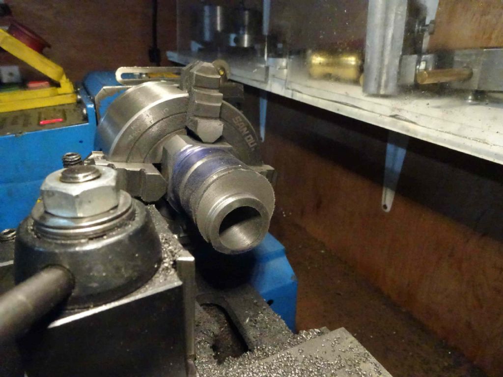
The task was to re-do the bottom cylinder plate which I'd manage to machine the spigot off-centre to the central hole (no I can't imagine how, either).
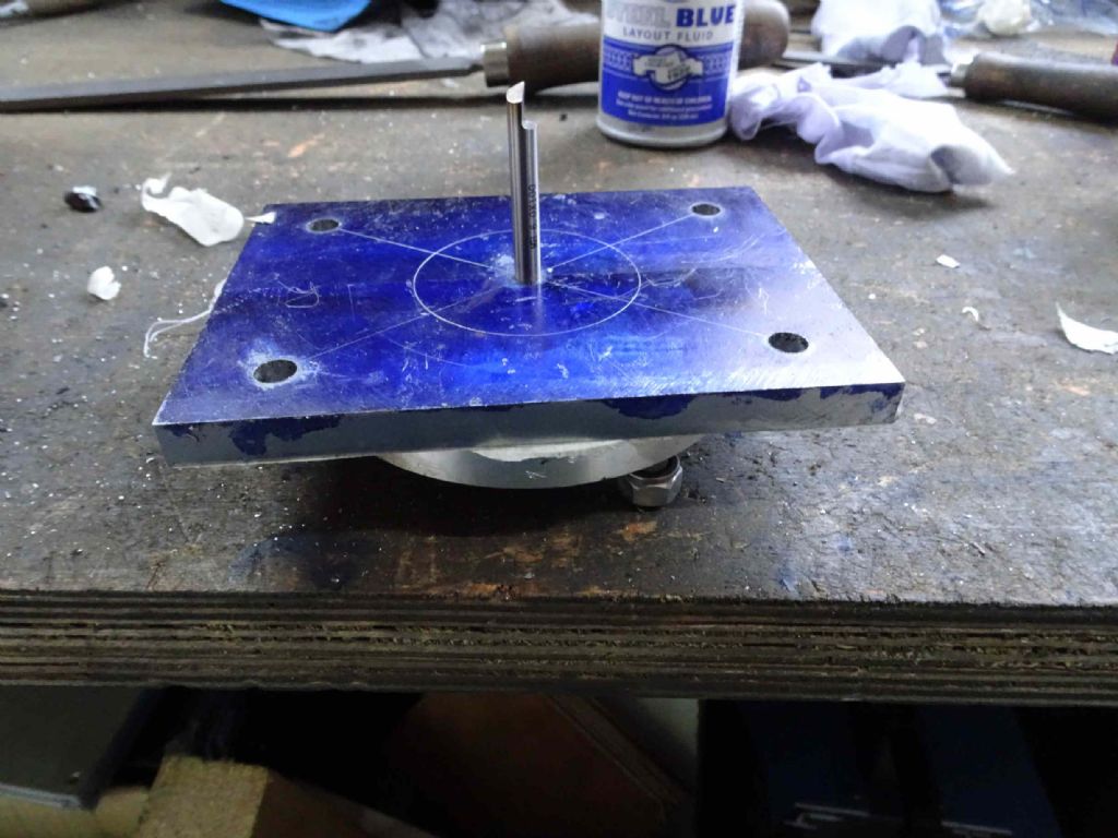
I started off by trying to use a superglue chuck. The chuck was snug to the chuck plate with a 6mm hole in the centre. The plate has a 6mm hole in the centre and I located them with some 6mm round toolbit material.
When I put them together on the lathe I noticed that central hole didn't seem central. So I got my indicator out and it seemed to be 0.5 mm off. Which I thought was too much.
Actually, I then spent quite some time (whilst working on other projects) trying to work out how to hold the plate.
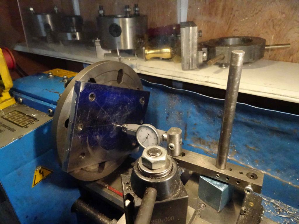
IN the end, I drilled and tapped two M6 holes on the outside edge and mounted it on my face plate.
A bit of tapping and I got it reasonably centred (0.02/0.03 mm)
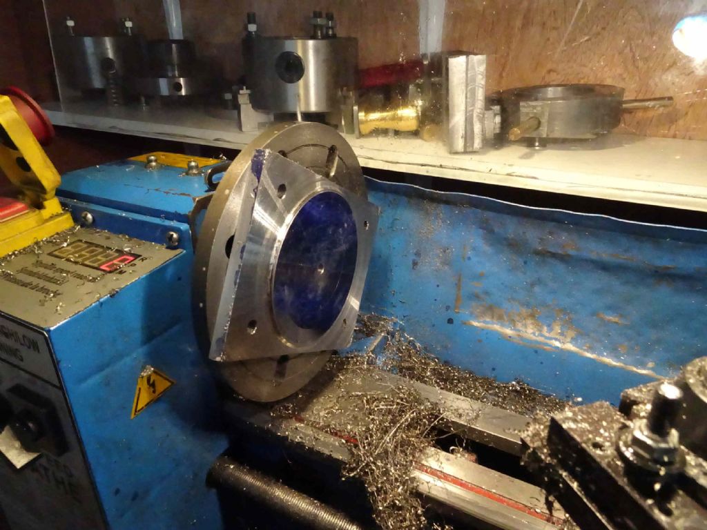
Next a rough cut to get 2mm down through the area which had an interrupted cut. I have interrupted cuts. I have to run the lathe at a higher speed than I feel comfortable with or it stalls.And sometimes it sticks or stalls anyway.
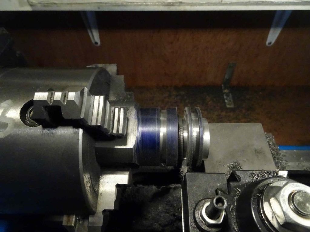
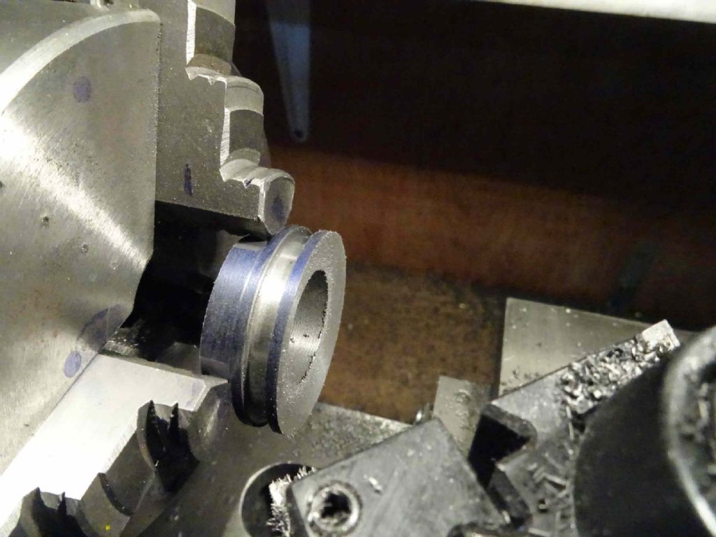
Then it was taking the rest down to a 50mm diameter and boring a 20mm hole in the centre. All very gingerly and trying and fitting with the cylinder and piston gland.
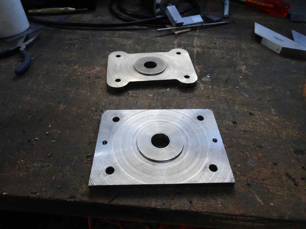
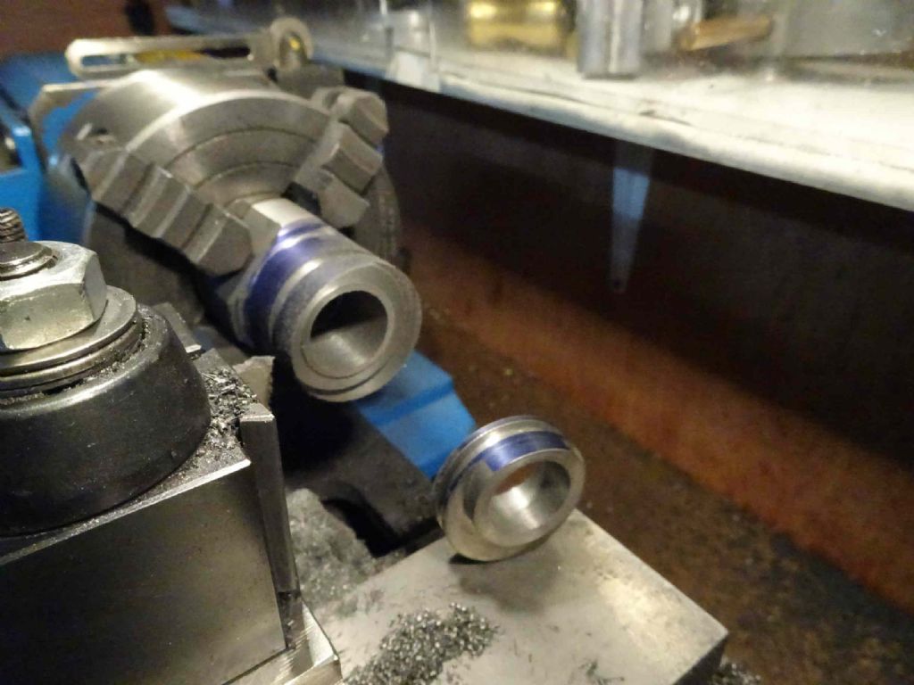
Here we contrast the new one and the original (bad) one. this time as you see I've done the bits where the registration matters before the cosmetics.
And, guess what? It all fits together!
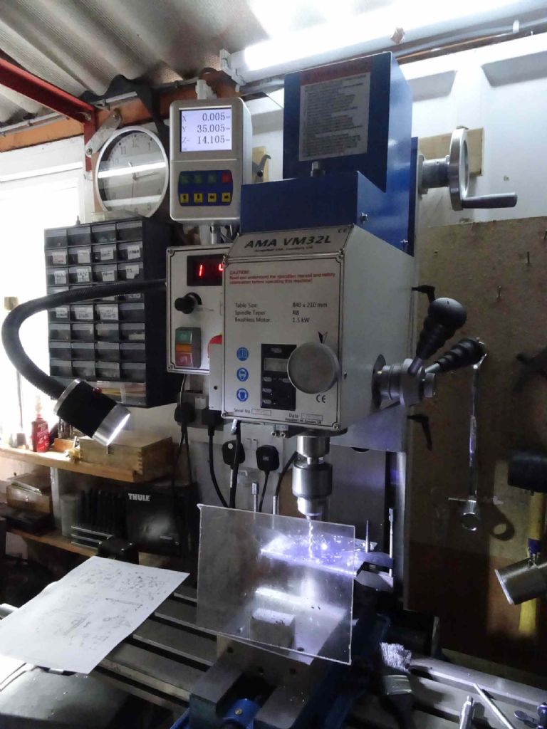
Next I needed to prepare the fixings for the cylinder. This is where my new DRO gave me a great deal of happiness.
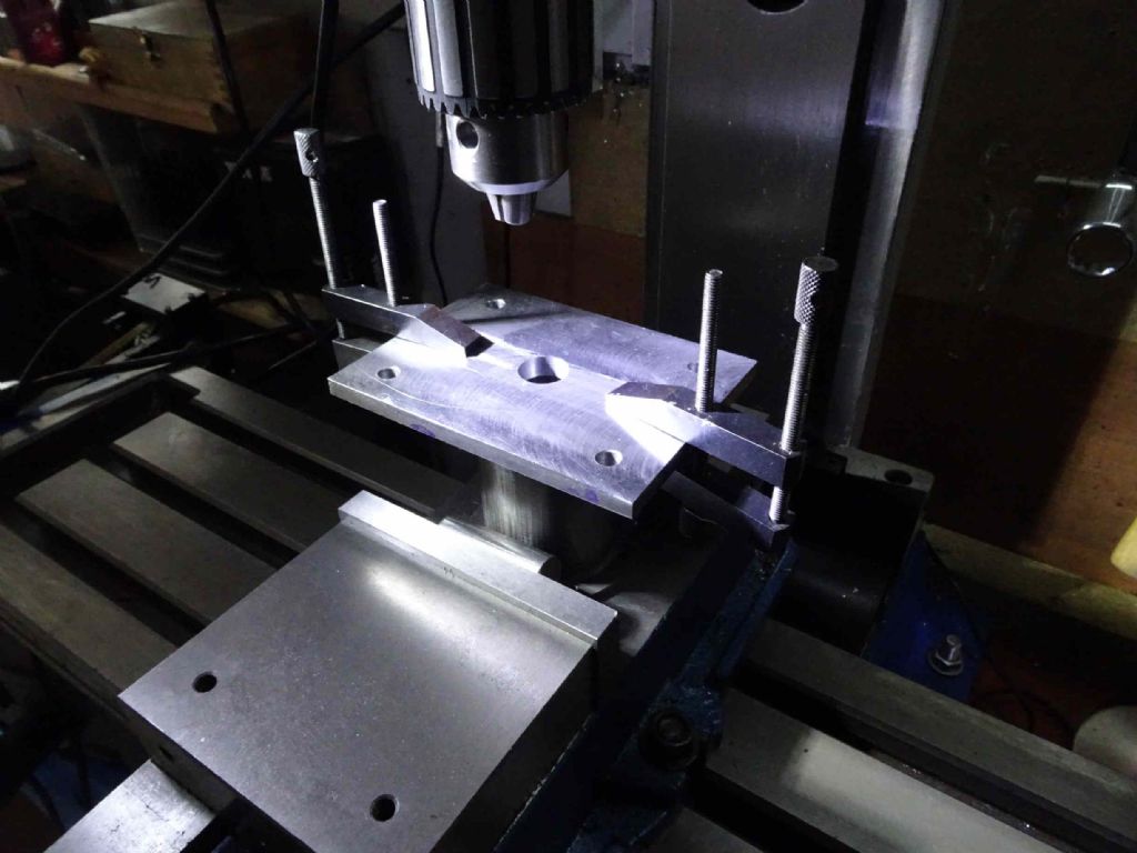
First was to clamp the cylinder to the plate and use some slip gauges to make sure the valve face was parallel to the back of the cylinder plate (this by getting a close approximation and 'feeling' – This is not something where the odd 0.05 mm will make a lot of difference) then to clamp the cylinder in the vice.
Although the DRO has something to make holes round a circle, I'd designed this to have a slightly wider gap on the port side of the cylinder. In hindsight not sure if this was required to clear the ports, but there you are. I took my design and made a drawing with the offsets of all the holes from the centre of the plate marked and used that work out the positions on the DRO
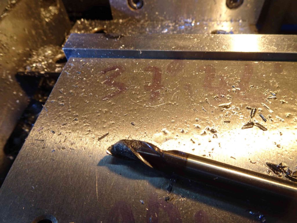
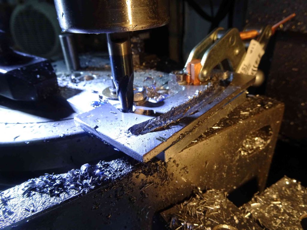
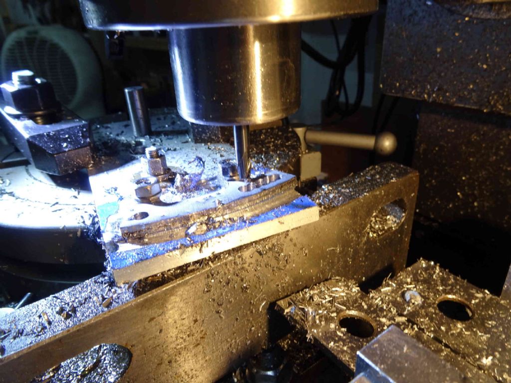
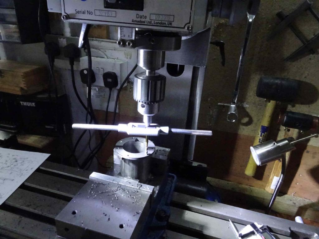
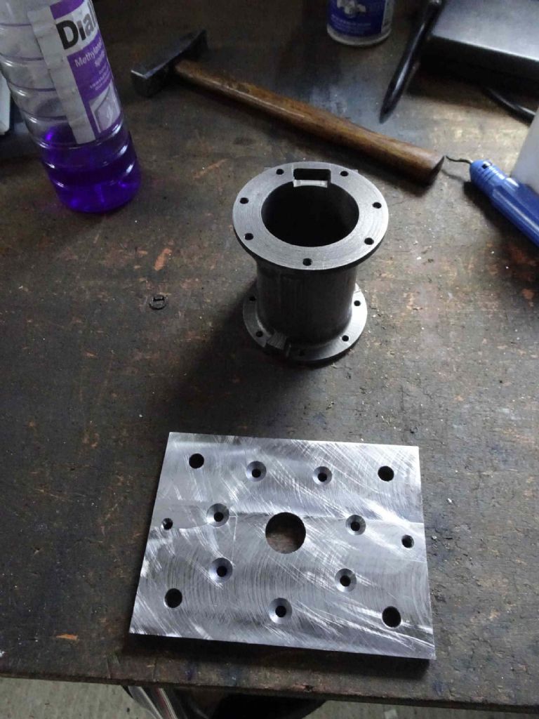
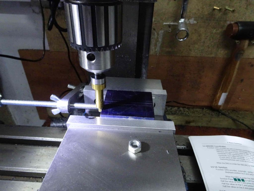
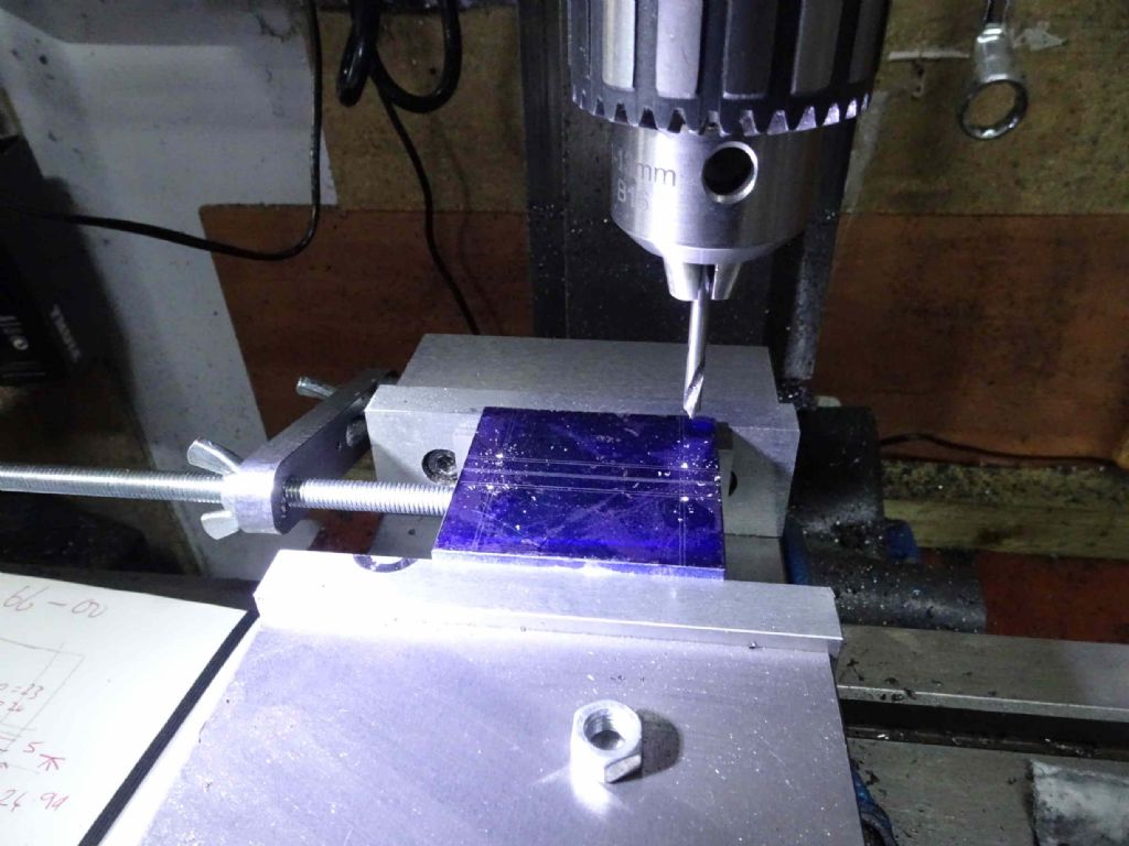
I first put 7 spots in with a 5mm Spotting drill , then changed to a tap drill and put 7 tapping holes in, then back to the spotting drill to go just down through the 7.5mm plate (I should have done this to start with and saved a step), then a countersink for the 7 holes and finally, swapped out to a tap.
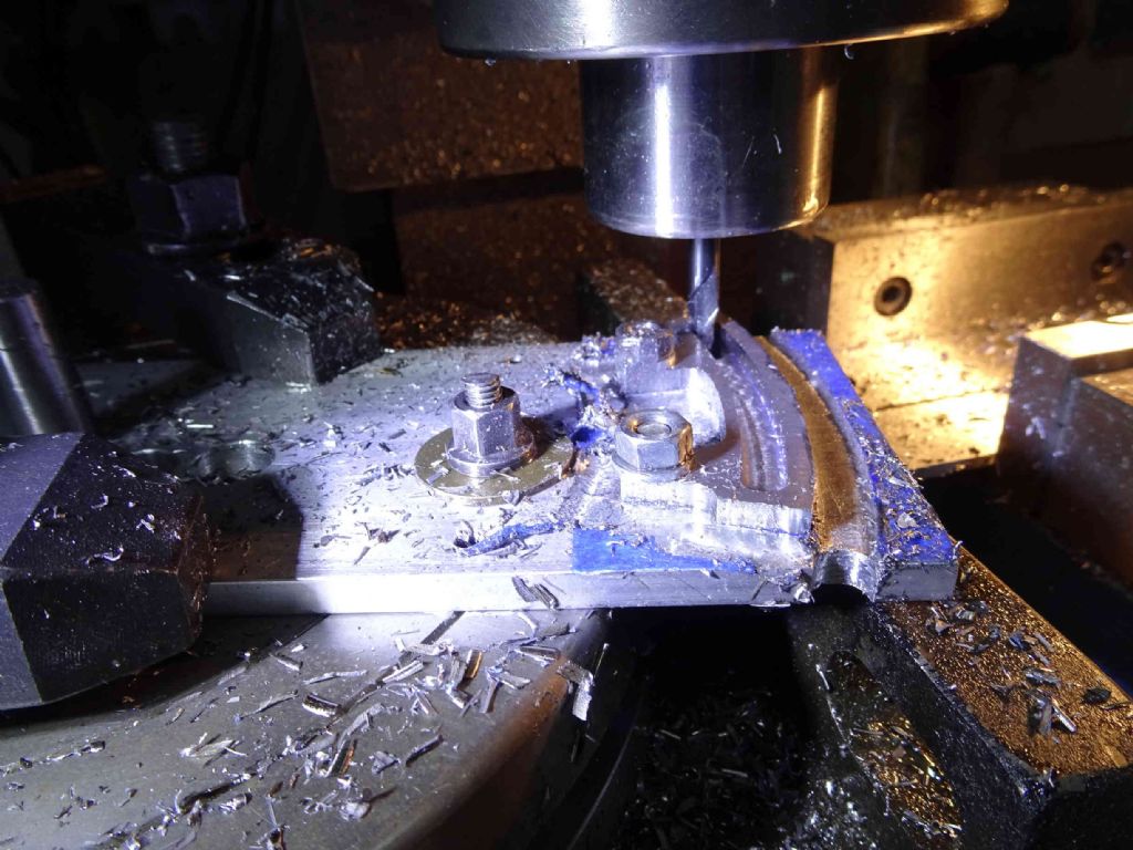
Doing this with the DRO was a joy. The top end I did on a rotary table with swapping between, drills, taps and drills for each hole!
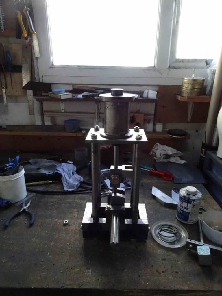
Here we go! Already for mounting!
Next step is the eccentrics. I might also want to rethink some of the decoration of this plate (rounded corners and so on) to better fit with the reversing gear.
It's nice to have some progress!
Iain
1 August 2020 at 20:31 #488705Iain Downs
Participant@iaindowns78295This phase of the operation shows that you often spend more time making the tools to make the parts than you do making the parts. Not that making the tools isn't as much if not more fun, but …
In this case, I've given some thought as to how to machine the eccentrics and I've come up with an approach that looks like this.
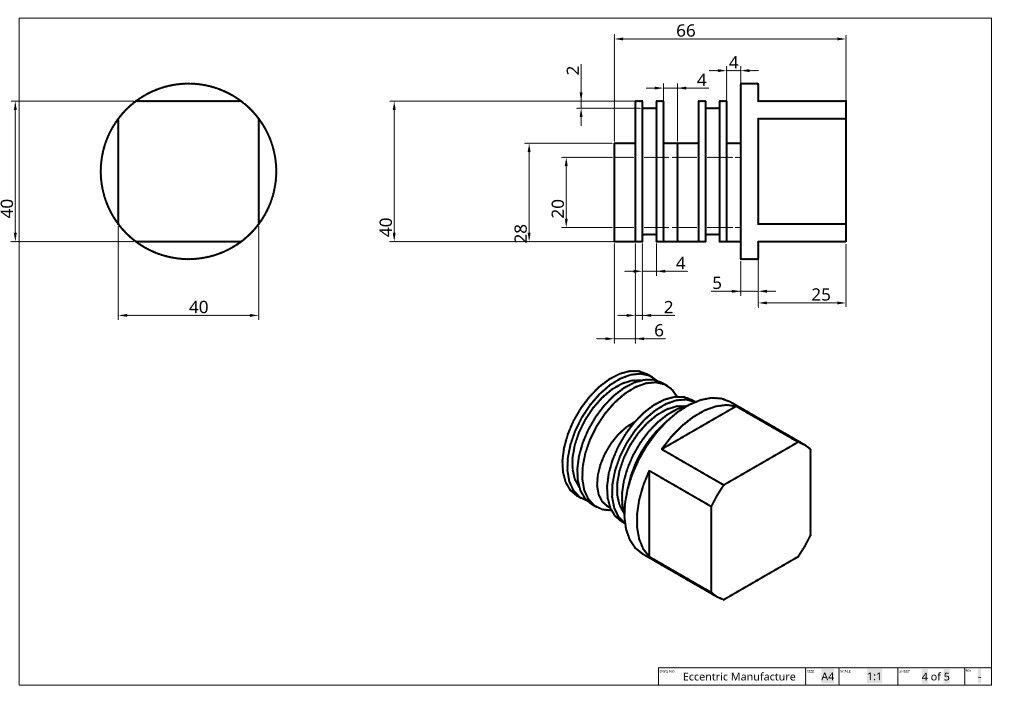
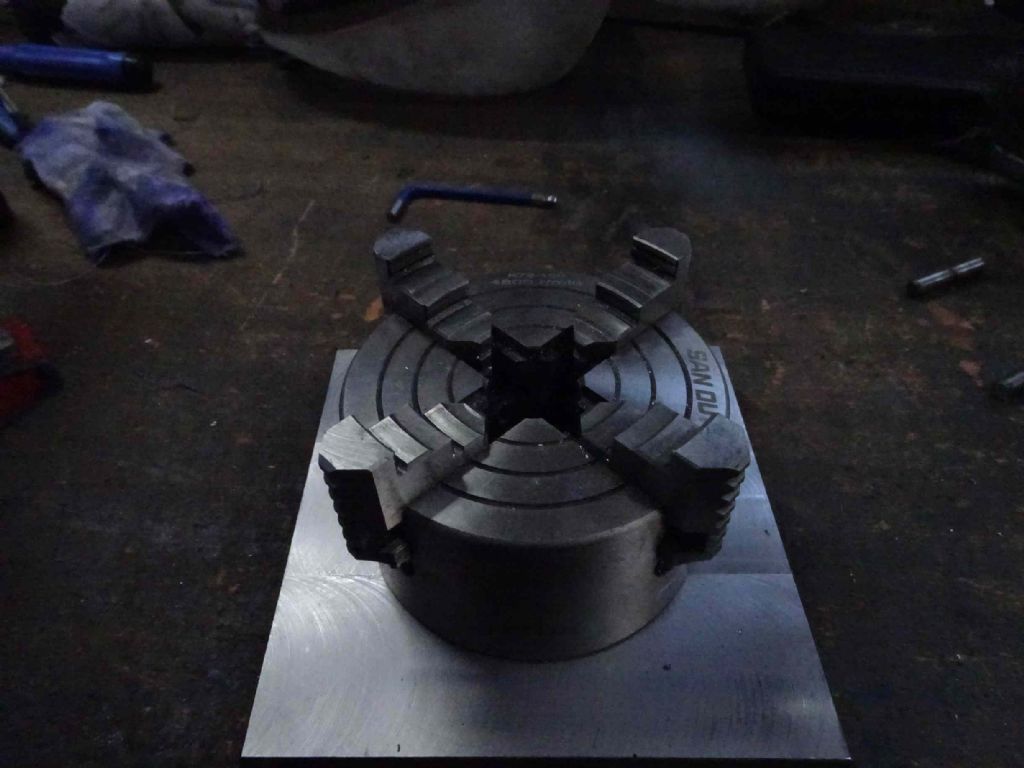
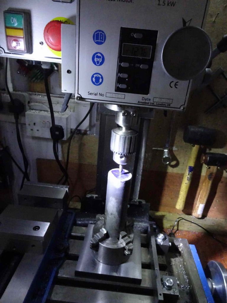
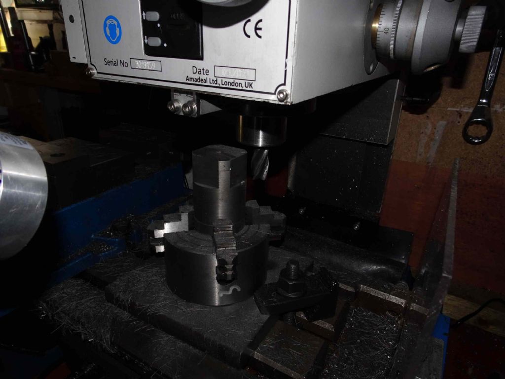
So the idea is to mill a square on the end of the cast iron bar to hold it in the 4 jaw. Then moving the piece to between the eccentrics and the offset of the crank will be (relativel)y easy. I worried about how to hold the piece on the mill (a round shaft vertical) and quickly decided a chuck was the right way. So how to hold the chuck? I chuck holding plate, of course!
I have some pieces of 6 inch square x 1 inch plate I bought many years ago for a first project which was going to be a lathe. Ah, Hubris! Downfall of the Gods and amateur engineers who over-reach. So the headstock sides have been re-purposed since for more practical uses.
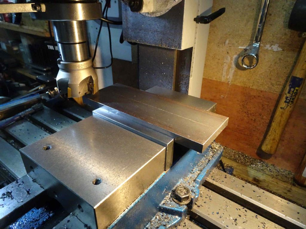
First, to square the sawn ends so I could put it in the vice
Then, for the first time, used the versatility of this ARC versatile vice. You can move the jaws around to hold bigger pieces – the standard jaws won''t hold a 6 inch piece.
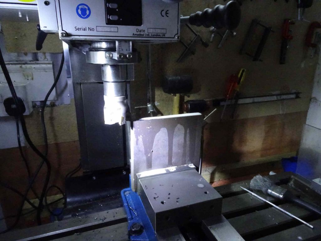
This worked really well and I was able to get a nice shiny flat plate.
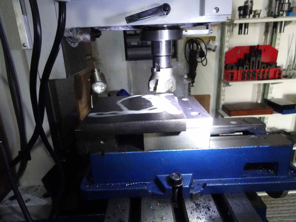
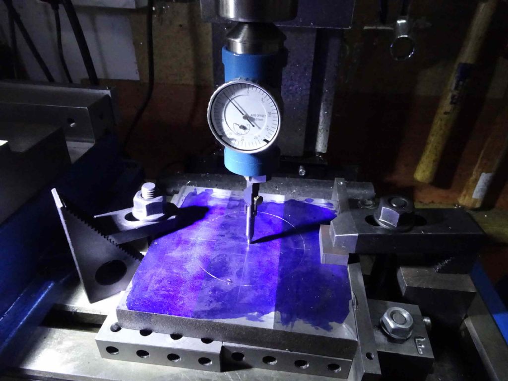
Now here's the exciting part. My first attempt to use the PCD function on the DRO.
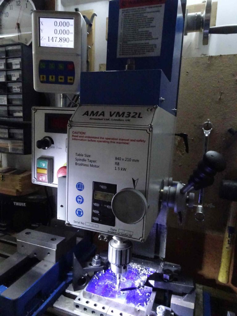
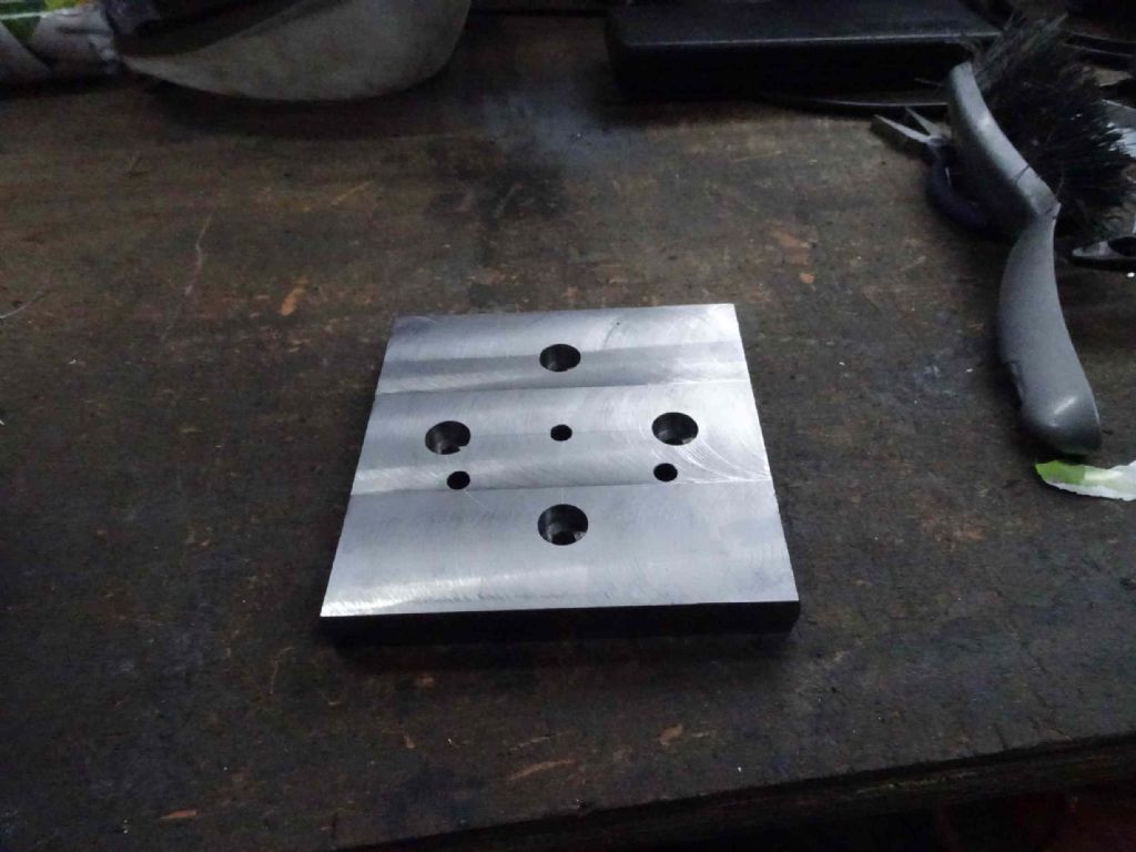
Set the centre of the plate up with the co-axial indicator and set the INC register on the DRO to zero. I have to say the DRO seems pretty good (but see later) but the chinglese manual is not the best. Once I zero'd I set the PCD to 84mm diameter, 5 holes (yes, for some reason you have to end up where you started, so drilling 4 holes means you have to enter '5'
 and start at 0 degrees.
Oh! I've just discovered you can set the picture size!!!
Anyway running through the holes is pretty easy, you just press <- and then wind the handles till X & Y are zero. The DRO really is transformational – in another tool to make the eccentric, I had to spot, drill and tap three holes. Before, I would have spotted, swapped to the drill, drilled, switch to the tap, tapped (manually) and then did this twice more. With the DRO, I set register 0 to 0, spotted, moved to the next position, set register 1 to 0, spotted, moved to the next, set register 2, spotted. Changed drill, drilled, selected register 2, drilled and so on. Much less swapping of tools!. On this piece I also managed to power tap successfully for the first time.
Anyway, here's what the Chuck holding plate looks like
I ended up making it suitable for 3 and 4 jaws as you can see.
And here with a chuck on it
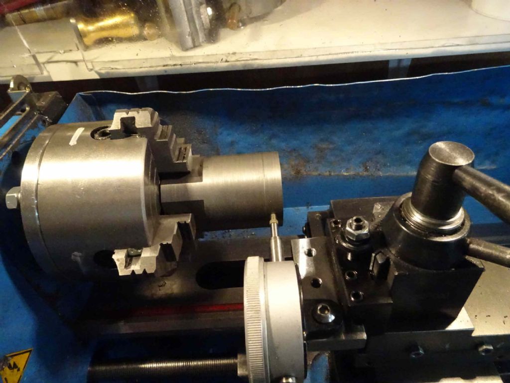
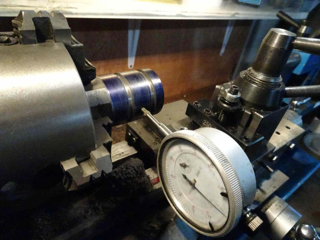
The other tool I mentioned above was something to hold my indicator in the QCTP – just a piece of mild with some bolt holes to hold the indicator. When I've tried to centre in the 4 jaw in the past I've used a lever type indicator with a very small degree of movement. It's to easy for an idiot like me to back the piece out of the range of movement of this – if I can get it in in the first place, so I'm hoping that this will make things easier.
The one peculiar thing (well something that went wrong, which is not that peculiar for me!) is that the chucks didn't quite fit. When I measured the diameter between the holes (and added 8mm to get to the centre), it came to a tiny amount less than 84mm. The fix was easy – just drill out to 8.5mm. I will do some tests on this later and see if I can work out what I've screwed up!
Next is preparing the piece for the eccentric.
1 August 2020 at 20:45 #488707Iain Downs
Participant@iaindowns78295And finally some work on the eccentric!
First I drilled a centre in end of the bar, holding it with the 4 jaw on the (aforementioned) chuck holding plate
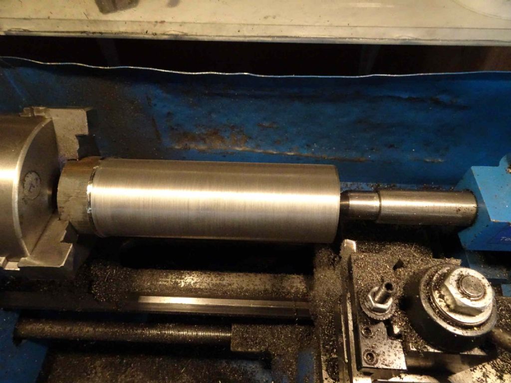
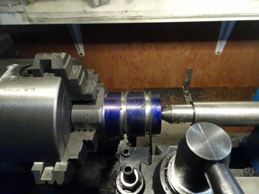
Then onto the lathe with a 3 jaw lightly nipped and the end of the bar in a centre
First few passes with a carbide insert which didn't really work too well – perhaps I wasn't taking enough off, it seemed to rub rather than cut – though the dust that's produced was hot enough.
Then finished with a nice traditional HSS tool. This reduced the 50mm bar to about 48mm – I wasn't trying for a particular size – just to get it nice and clean to hold in the 4 jaw.
Off the lathe and onto the bandsaw to cut a bit over 70mm off. This operation surprised me as the bandsaw went through the bar like it was butter. This in contrast with the hour it took to cut a (granted much bigger) aluminium bar. I see a blade with fewer teeth in my future before I cut more big ally!
Faced off both ends. This time with the same carbide tool which didn't do well on the outside. Worked fine for facing!
Then onto the mill for the squaring
Again, the DRO made this child's play. I used an edge finder to get the Y edge and zeroed the DRO, then the same with the X. Then moved the table to center the spindle over the centre of the bar and zeroed X&Y.
Oh – and I discovered why I got a 4 Axis DRO! At the time it was just because I could but didn't really know what I would do with it. After all the Spindle DRO would do all I wanted.. However, I realised here that I could use the Z to take the head down by 25mm with the spindle high and fully locked. In theory more rigidity! I'm not 100% sure this will make a difference in practise, but it certainly makes me feel better about the extra spend…
This is as far as I got today. There's the piece in the 4 jaw waiting to be indicated and the indicator mounted on the QCTP with the mounting bracket I made.
Frankly, I have yet to master (or even get close) to centring in the 4 jaw, so I was as pleased to leave it for another day…
Iain
13 August 2020 at 20:43 #490509Iain Downs
Participant@iaindowns78295A couple of weeks later and the eccentrics are done! For the main part this has gone better than I expected which is pleasing.
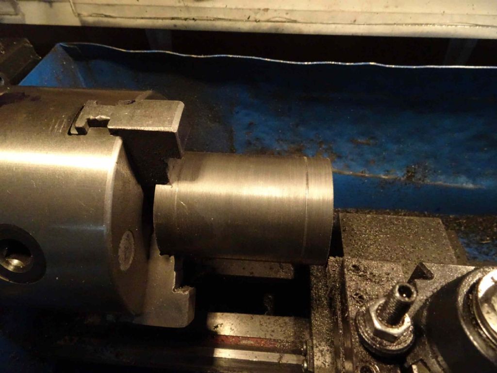
In the previous post, I ended up with a round 40mm cast iron bar held securely in the 4 jaw. The first task was to put 4mm groves in for the straps. FIrst step with this was to grind a tool, more or less a parting off tool, but a bit under 4mm. Then to make the 2mm deep grooves.
A bit of chatter on this, but this was cleaned up when I slid the tool sideways to open the slot out to 4mm.
Next step was to offset the bar by 6mm. This went surprisingly well, using the 2 key approach.
next step was to turn the collar on the end
Then came the nasty bit.
I needed to part off the first eccentric. If I thought parting off was a challenge, let's try it on an interrupted cut!
The was very very slow going, feeding the tool in very gently to try and prevent a jam. For some reason I decided to use the 4mm tool to get most of the way down and then 'finish off' with a 2mm parting tool.
At this point, disaster struck! There was a solid jam, the lights went out,, flashes came from inside the lathe electrics and everything stopped.
I'd blown one of the sets of breakers in the house. I took this as a message – it was about 9 o'clock (a self imposed deadline to stop the neighbours getting irate) and clearly time to stop.
The next half hour or so was spent resetting the RCD, rebooting PCs and fixing networking issues. In fact I was still struggling with connect problems when I started work the today!
So tonight I went back out to the shed, thoughts of fried thyristors uppermost in my mind. But to my surprise (and relief) the lathe started up straight away – I hadn't even blown the lathe fuse…
Back on to the parting off
Eventually, this was done and I set about the second eccentric.
This time I decided that parting off this type of thing was NOT my idea of fun, so I took the piece out of the chuck and cut it off on the band saw. This was both immeasurably quicker and a great deal less stressfull.
Swapped the chuck for a 3 jaw and popped the piece back in to clean off the back.
Next step was to pop them into the milling vice and drill and tap an M4 hole for a grub screw and here we are!
Most likely, the next work item are the eccentric straps. To be honest, I've not yet worked out how to machine these. I've seen that there are videos on youtube and no doubt advice in this august forum, but I've not got round to looking.
I was wondering if I should make the straps in steel or brass. I was thinking steel, but brass would like nice, wouldn't it? Any reason why not?
What I may do before that (if I have to wait for material, for example) is to mount the cross head guide,
I can feel it getting close!
Iain
13 August 2020 at 20:54 #490512 JasonBModerator@jasonb
Steel/iron is a common combination though I would have gone for iron straps and steel eccentrics.
13 August 2020 at 23:06 #490527Nigel Graham 2
Participant@nigelgraham2two questions you asked:
Cast-iron sheaves with mild-steel straps? Yes, no problem, since anyway I think you've made them! I note Jason suggests the other way round, but I have not seen a definite choice either way. In full-size it was common to use cast-iron for both.
Locking the reversing-lever in its running and mid-gear positions. The usual way is to fit a small sprung catch operated by a trigger on the handle part of the lever, engaging notches in a quadrant plate that also supports the lever from side-ways forces. Plenty of examples on locomotives and traction-engines, as a guide to designing yours.
Another way you could go: Without knowing for certain your choice, your engine suggests smaller marine practice, so you could fit a similar but plain quadrant with an arcuate slot in which works a small clamp-screw fitted into the lever just below the handle, and locked by a little handle of its own. I have seen that on example drawings in old text-books I own. The reason was that a ship's engine works almost entirely in forwards gear without adjustment – on a full-size ship for days or week at a time. (The bigger marine steam reciprocating engines had screw-and-quadrant reverser controls, or steam-reversers, though, to move a lot more heavy steel and iron.)
16 August 2020 at 14:50 #490933Iain Downs
Participant@iaindowns78295Jason – thanks for the advice and link. I've since reviewed some you tube and have a feeling about how to make them. The steel is on order.
Nigel – again, thanks. I confess that I'm building this engine to build it and not with a specific application in mind. The original design criteria was something that would run my lathe. Since then I've thought of a steam powered go-kart and, yes a marine engine.
Frankly I will delighted if it just runs at all!
Off out now to do a bit of work on the crosshead guide.
Iain
16 August 2020 at 16:25 #490950Kettrinboy
Participant@kettrinboyIain I think most of us are happy just to get an engine project to run even if it's just a few revolutions, all of my 8 hot air engines and one IC run but none of them have done more than about 15 mins total running, for me its just the challenge of designing and machining rather than running them for hours on end.
11 September 2020 at 12:12 #495255Iain Downs
Participant@iaindowns78295I've started work on the straps and this is my plan.
First make some blanks, 66x60x8mm.
Cut out shoulders for bolting the two halves of each strap together, drill and tap.
Slit the two halves apart.
Bolt together, drill and bore ( on the mill) the centre and then the flanges.
Mount on a rotary table and take away the bits I don't want.
Phew! sounds easy?
So I started with a largish piece of steel – 200mm x 100 x 10 and trimmed it down on the mill.
First step was to get the edges reasonably straight so I had something hold for the surfacing.
then to reduce it to 8mm. This wen pretty well. I ended up with it with 0.04 mm across the whole area, most of the error being due to a hump in the centre. This in turn probably due to using 80mm parallels on a 200mm work piece. I've longer parallels on order.
Next to take it down in height and trim the edges now I had some nice clean surfaces to work from.
To the bandsaw and off come my two prospective straps,then trimmed to exact width on the mill.
Marked up on the surface plate as a check, but then back to the mill to use the DRO to mark and drlll some nice round corners for edge relief.
The stop was used so that I only need to edge find once. The two pieces being within 0.01 / 0.02 in all dimensions (somewhat to my shock).
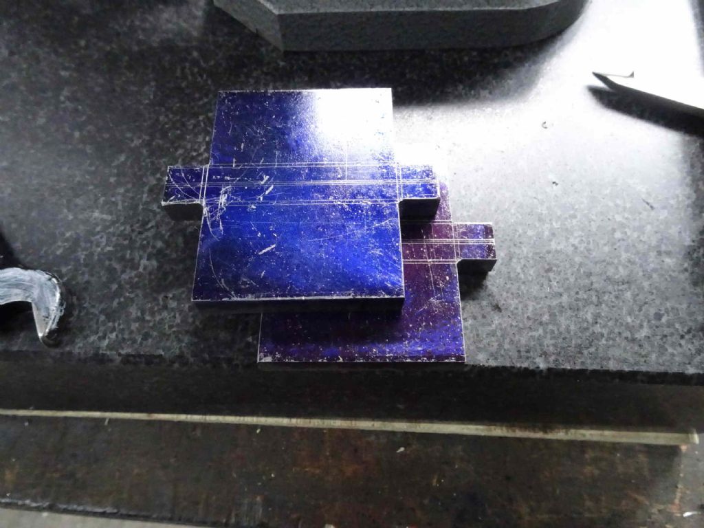
Then flip the straps on their end and carve out the unwanted bits. I had to do a bit of cleaning up the relief with a small file, but you won't tell anyone will you?
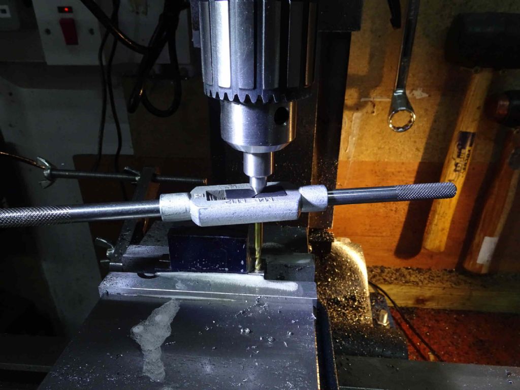
Back to the mill to be drilled and tapped.
The lovely DRO let me spot, drill, tap drill and tap without having to change tools a million times. Thanks, DRO!
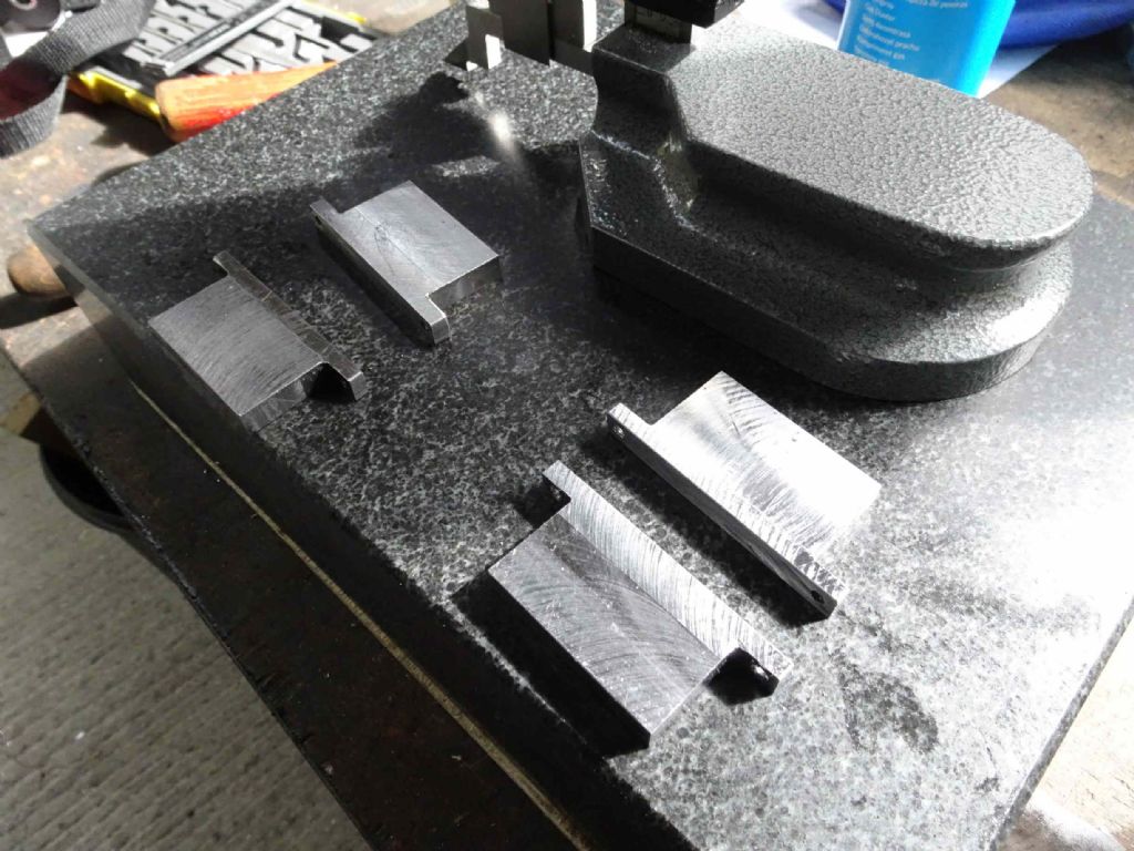
I've used my Father's day letter punches to mark which bit belongs to which so I don't get them mixed up after slitting.
That's it for now. Next step is to bolt them together (may also superglue) get them back in the mill, drill and bore.
Again the DRO will help here as I can wind the Head up out of the way to measure and be sure to get it back to where it was so I have a nice clean depth of cut!
Iain
20 September 2020 at 10:14 #496858Iain Downs
Participant@iaindowns78295I was rather dreading this bit. Boring out the strap, which requires a fair amount of precision on all sides. I still think that the accuracy was more luck than judgement – but who's complaining?
The first thing I did was to skim up the faces of the joint of the strap. I'm blaming the mount in the vice which didn't provide enough support, but the two pieces weren't straight when bolted together. This was just the lightest skim, though I fear that the centre line is no longer quite on centre.
Having done that I bolted each half together in the vice (to make sure the two halves were dead in line and clamped it in the vice on parallels. I dithered about this, wondering if I should put some kind of support under the centre line, but in the end did not and there was no drama.
First task was to centre the item (edge finder and the half option on the DRO – I STILL love my DRO!).
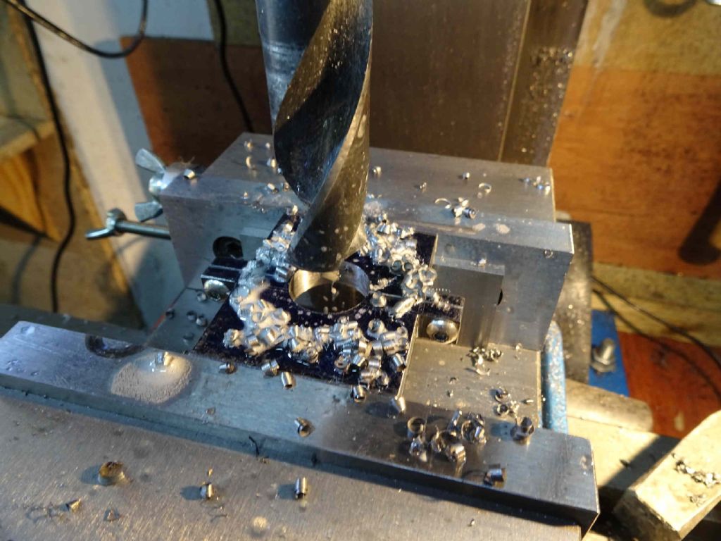
Then to drill. I started off with a 4mm stub drill then up to 6, 8, 10 and 12mm. I also love stub drills (thank you Model Engineer forum for my training!).. Then a14mm blacksmiths and a 20 mm blacksmiths. Again no drama.
Now it was time for the boring head. My mistake here was not to lock the Y axis (I'd locked the X but for some reason not the Y) and the table had drifted a little. Were it not for the DRO, I would neither have noticed nor being able to fix it (did I mention how much I like my DRO?). I simply put the Y back to zero and locked it. Naughty Iain.
I was a bit concerned about how to measure the groove depth and width. I could get the depth right by using the quill DRO, but the width required a measurement which was blocked by the boring head. DRO to the rescue! (Are you getting a theme here!). I zeroed the Y DRO and locked. Then zeroed the quill DRO as it touched the surface. Thus I could move the head out of the way and get it exactly back where it belonged afterwards. Not quite that simple as locking the Z moved the head a couple of thou, but that wasn't to hard to work round.
Everything seemed to work well in that the try fit of the eccentric worked, but when I tried to assemble the whole lot it just didn't' fit. :

After a moments thought it occurred to me that there was probably a small radius on the boring bar, but the eccentric edge was quite sharp. So I had a bit of a go on the eccentric with a smooth file and the strap with a pointed scraper.
Nearly! but not quite. Close though. Finally, I got some 7 (microns I think?) diamond paste, assembled it, added a dummy crankshaft and give it a bit of a lapping.
Some turns with the bolts tightened a bit every few turns and the eccentric is running smoothly in the strap! Cleaned off with WD40 and job done (for now).
I'm hoping my luck holds for the next piece this afternoon (if all goes well), then I all I have to worry about is how to mill the outside round.
Iain
7 October 2020 at 21:03 #500127Iain Downs
Participant@iaindowns78295This episode is entitled, 'sometimes the hard way is the easiest'. You'll see why later on.
Frankly, I've been worried about these parts – they require a level of precision I admire but rarely manage to reach. However, they've gone quite well.
The boring of the second strap went slightly less well than the first one in that I didn't quite bore out enough so the eccentric didn't quite fit. However the vice stop meant that I could get it back in the same place and re-work it. Getting the boring bar at the right dimension was a bit tricky, but in the end it worked out. Again, a certain amount of grinding paste was needed to get the eccentric running freely in the strap.
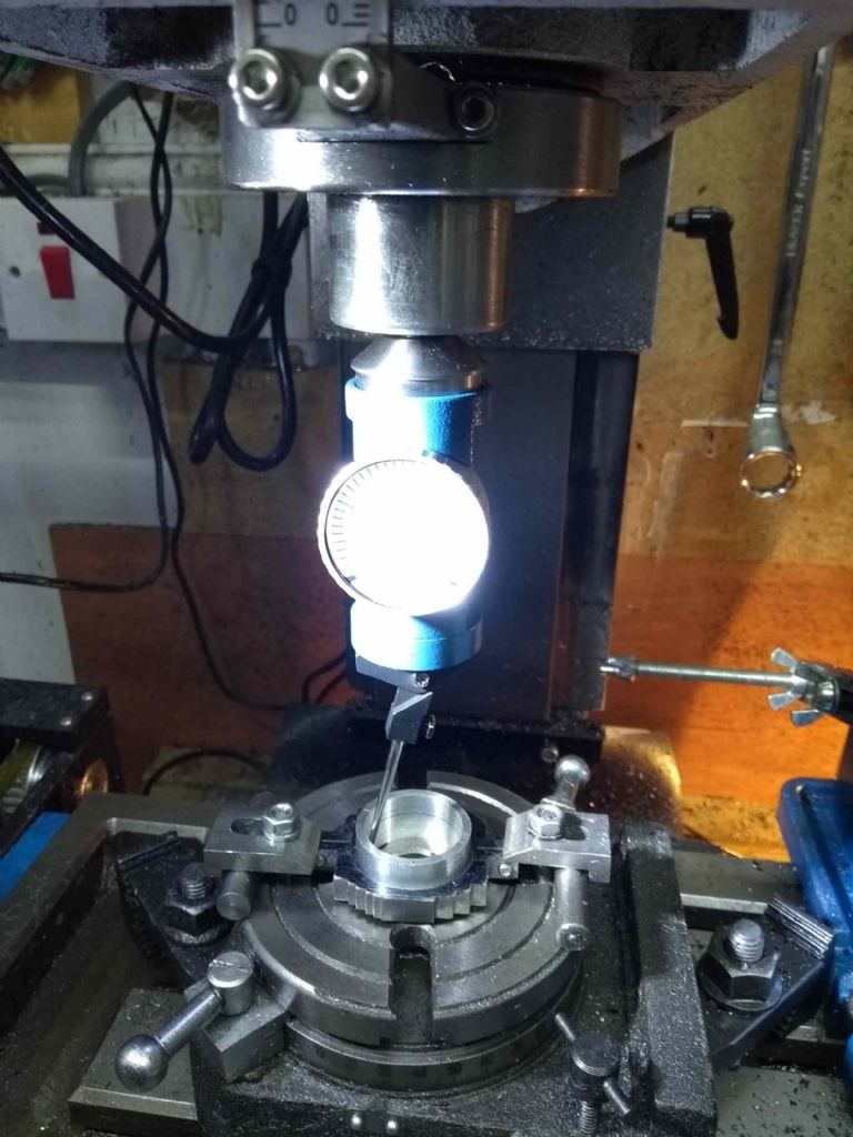
When I thought about machining the outside of the strap, I was worried about getting the piece centred on my rotary table which is quite small (yes a big one to match the Mill is on my shopping list – somewhere). There's not much space for clamps and adjustment via hammer struck me as being uncertain.
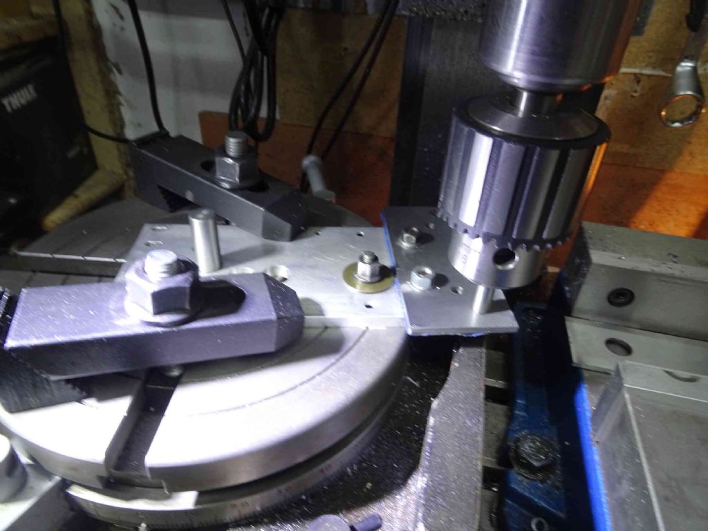
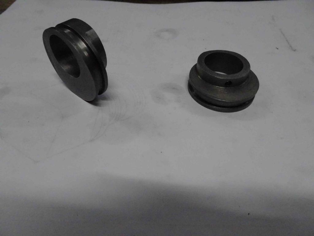
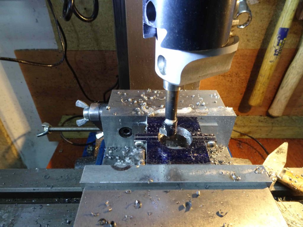
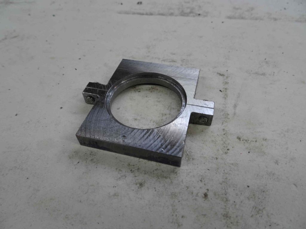
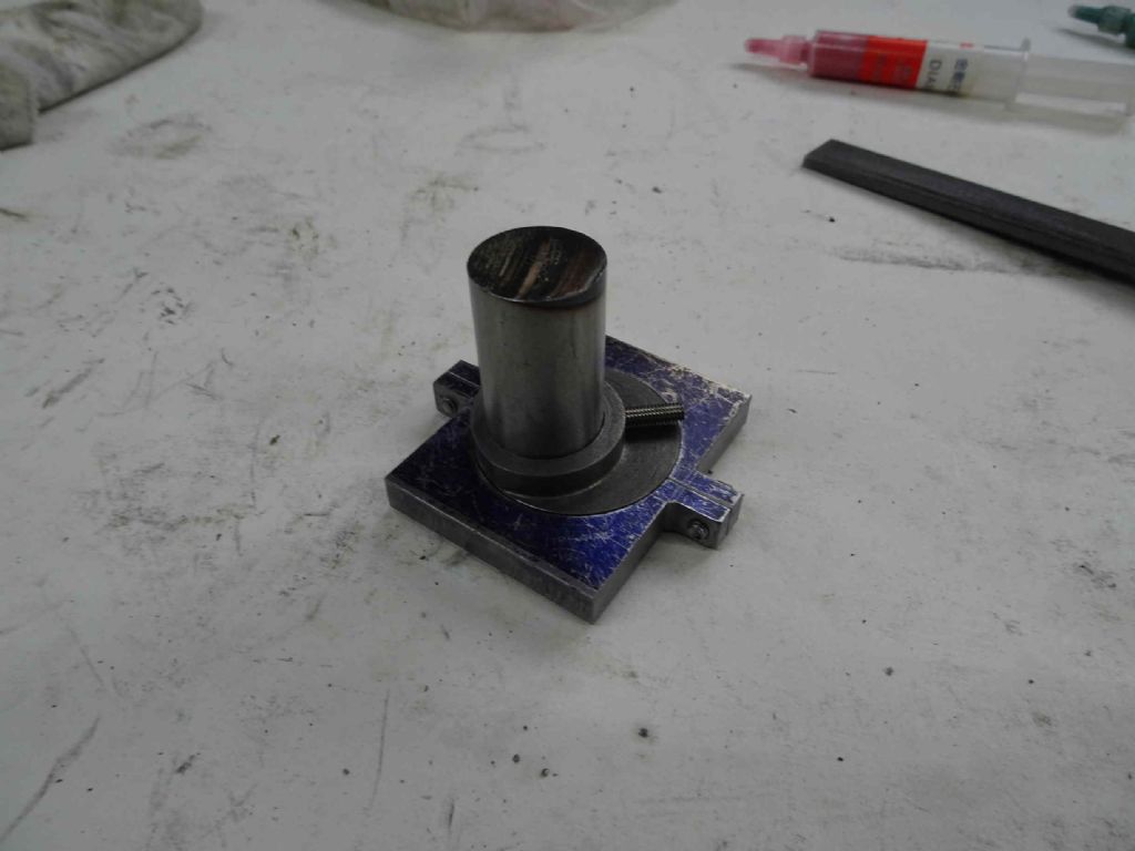
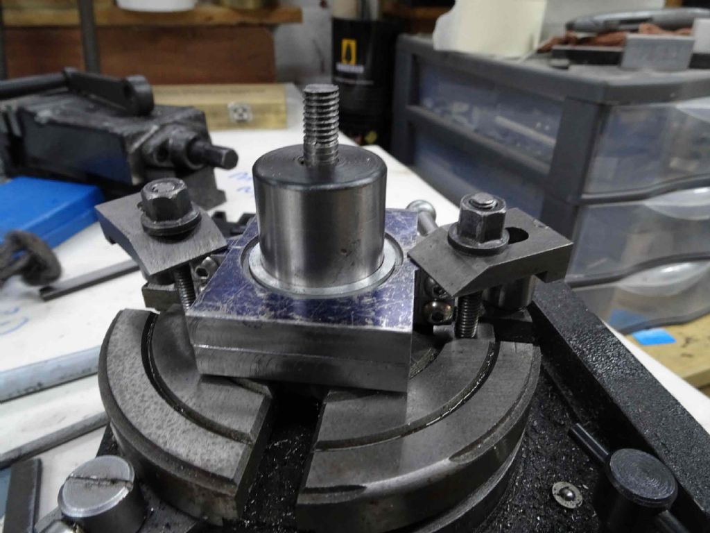
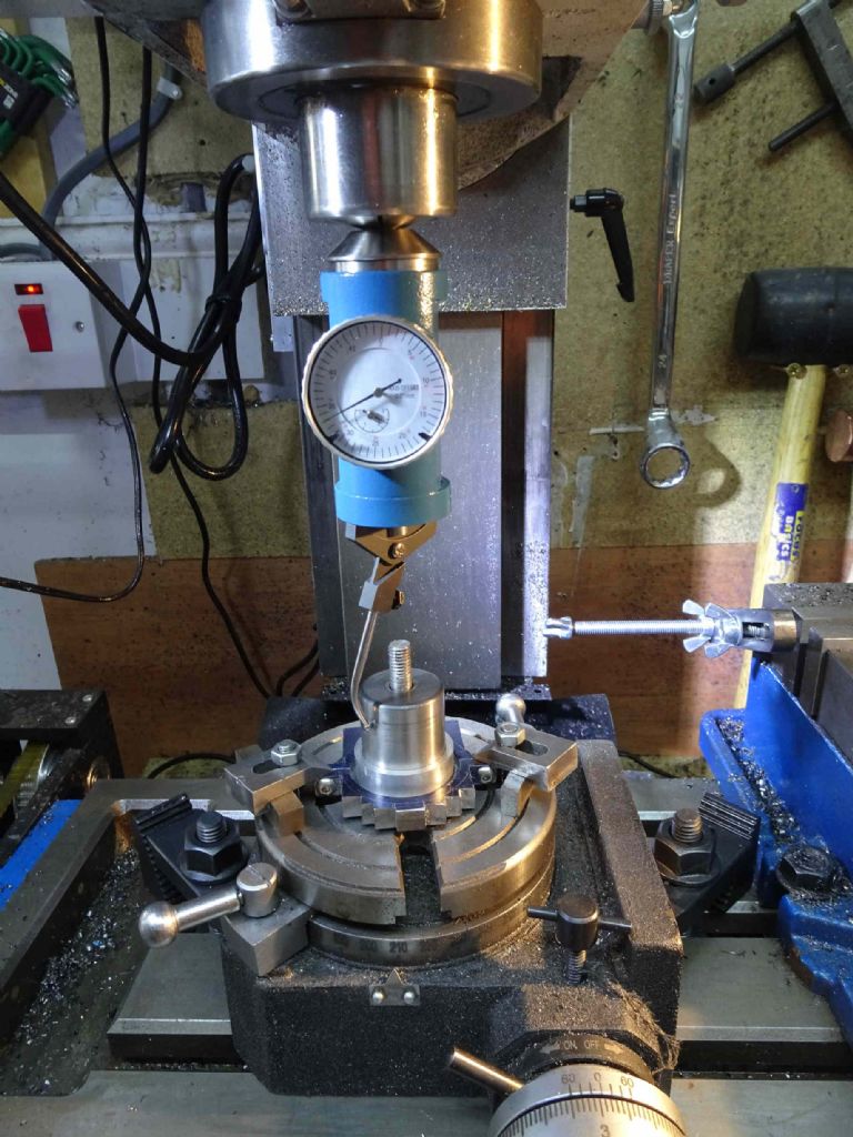
After some thought, I remembered I had a blank end MT2 arbor which would fit nicely in the table and I made a collar which went over the arbor and which the strap rested on raised a bit from the bed of the table.
This picture shows the arbor, the collar and the clamps. As it turned out I couldn't get to the bottom one with a 4mm end mill so I did them one at a time. Also the clamps didn't really work with a rectangular support behind them and I ended up putting a bar inside the back end of the clamp – you'll see that later.
The idea was to get the arbor indicated and job done (apart from the milling, of course).
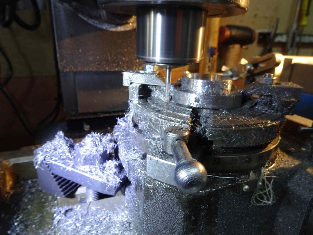
You can see that I'd trimmed a bit off the top of the strap, but I didn't do so on the bottom. This proved to be a mistake. There was a lot of material to take off the bottom with a 4mm end mill. Also, as it was small, and fast, the swarf was very small and very nasty, getting everywhere – mainly into my fingers. Ugh.
On with the milling!
Nonetheless, this worked and I ended up with a strap I'm quite happy with.
Having cleaned this off and sworn at the splinters, I decided to call it a night.
The next day I went back in to do the second strap.
First thing to do was to trim off the excess in the vice so there's less to cut with a small cutter – no problem! I've probably been a little over excited with one cut which may mar the beauty of the finished product, but I'm no perfectionist (as you can all tell).
Now get the arbor and put the bits back on the rotary table.
Hmm. Where IS the arbor?
Frankly I have no idea. I spent half an hour looking, gave up. Came back in the next day – no luck. Tidied the shed, looked in the bin, opened all the draws, moved the cupboards. Nope. It has gone.
A few more days sulking and eventually decided to order a replacement
 That's usually enough to unearth lost things.
Tonight I went into the shed with something else in mind and thought, 'Damn it. I'll have a go'!
By which I mean getting the piece centred on the rotary table with the aid of a hammer.
This turned out to be much quicker than I expected. 3 or 4 minutes of tapping whilst the centering indicator whirred round and it was set up within about 0.02mm. I decided I would take that. It didn't even move when I tightened down the nuts.
So what I thought was the hardest was in fact the easiest and would have saved me quite some time making the collar!
The other thing I learned from my first one was to use the DRO to get the outer diameter consistent (more or less). With the first one I was basically eyeballing it from the layout marks.
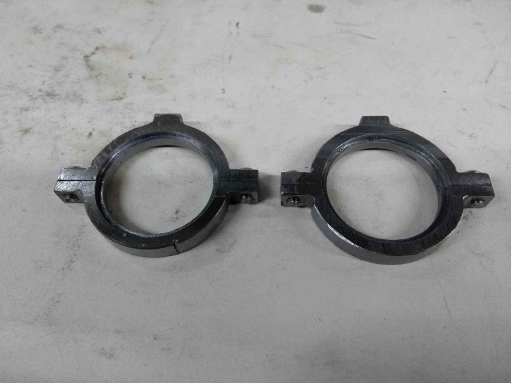
So here we have either some trendy eyeware in progress or a pair of half decent eccentrics.
My question of the day is – do I need to add an oil inlet for lubrication or is the occasional greasing enough?
I'm not sure what's next. I do want to continue with the valve gear, but I might need to adjust my drawings first. I notice that that there's some interference between the parts in the model. I expect I'll look at the expansion link.
I have a plan to build a die filer which would make this a little easier (and building tools is fun) so I might have a go at that first.
Iain
8 October 2020 at 06:59 #500159 JasonBModerator@jasonb
As yours are iron and quite thin plus the fact you did not leave a "lump" for the larger top hole of an oil hole I would say just apply a bit of oil to the side of the strap and it will find it's way into the surfaces that matter.
4 January 2021 at 21:19 #517522Iain Downs
Participant@iaindowns78295There's been quite a gap since my last post – a time in which no work has been done on the steam engine, though a bit in other areas.
The next item on my list was the Stephenson's reversing link. This is generally a curvy little thing and if I was Clickspring, I would get out my fretsaw and files and carve it to within a micron of it's life. Indeed if I had a motorised fretsaw, file and sander I would still consider it. But doing the whole thing by hand struck me as being a bit of a bind.
Plus I wanted an excuse to buy a bigger rotary table.
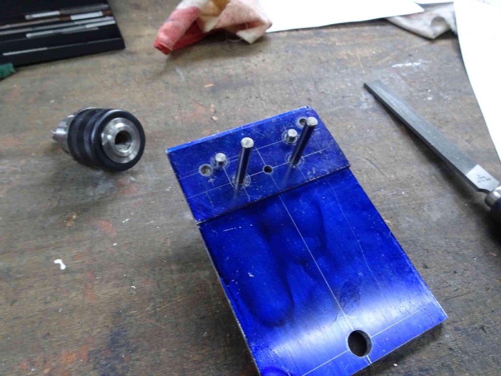
Despite having a bigger rotary table it's still a little small, but I think I will make do. My basic idea is to make a fixture which will sit on the rotary table and extend a bit beyond it.
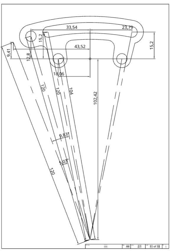
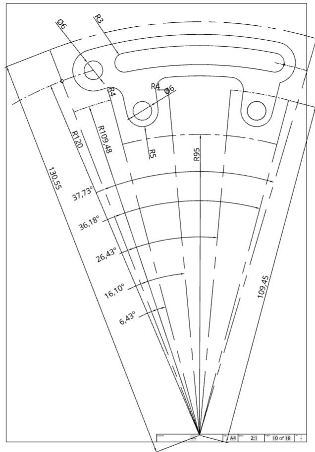
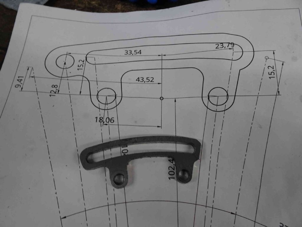
The fixture will have some alignment holes and a piece of 4mm steel will be (probably) superglued to it. The image below gives an idea of how that would work. I'm still not certain if I will drill the 3 holes in the steel (referenced from the small circle between the lower holes or just glue it in place and not worry too much about orientation
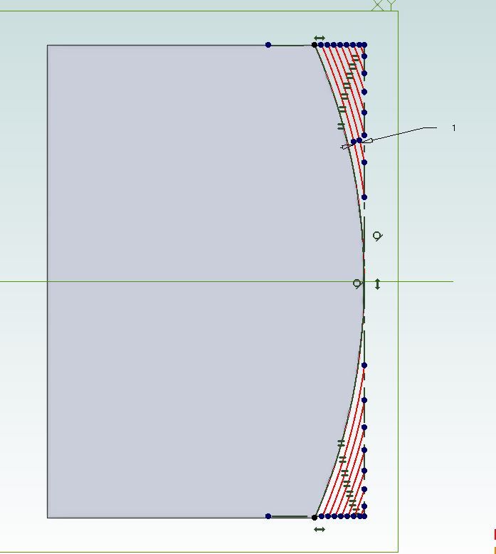
Next is to carefully move the X axis and rotary table to carve the basic outline. Angles in the diagram below would be converted to degrees and minutes and I would end up with a piece which looked like the below but with squared off ends.
Finally, the piece will be removed from the fixture, centered around the round holes and the curves formed.
You will see that pretty much all the link will actually sit outside the 200mm rotary table. Not ideal, but I think that with a reasonably stiff fixture I'll be OK.
I'm not sure when I will get to this. My shed is unheated and uninsulated. The fan-heater will bring the air cold up to cool in reasonable conditions, but the machinery remains cold and catches a lot of moisture.
Yes, I know. I'm a wimp.
One thing I want to do is to chop down an MT3 blank end arbour so it sits below the surface of the rotary table and put an reamed hole down the centre so I can centre fixtures and the like with a pin. I'm still debating that.
Iain
4 January 2021 at 22:51 #517536Paul Lousick
Participant@paullousick59116Hi Iain,
I had a similar problem making the Stephensons link for my engine. Mine is a bit bigger than the one you are making and has a 335 mm radius instead of 120 mm.
I only had a 150mm dia rotary table and mounted an extension plate to it. The end of the extension plate sits on a support and is captured on the top to prevent any vertical movement. (Milling a curve on a large radius puts a lot of load on the rotary table which I found out the hard way by stripping the worm gear). The rotary table is only used as a pivot point and rotary movement done by a horizontal lead screw at the end.
The material for the link was laser cut from plate and designed with extra lugs for mounting and cut off after machining. The internal slide for the link (shown in LH photo) was made in a similar way but made extra long so it could be bolted at each end and cut to the required length after machining the curves.
As your part only overhangs the rotary table by a small amount you should be OK, just take it easy with light cuts.in a convettional milling direction. Climb milling will drag the job and hammer the gears as you rotate the table.
(The RT has a 3MT taper and a spigot at the end for locating mounting plates on centre)
Paul
Edited By Paul Lousick on 04/01/2021 22:59:39
5 January 2021 at 09:26 #517590 JasonBModerator@jasonb
When I did the one for my Fowler I clamped the 10" length of gauge plate to the rotary table and cut the part from th eend of that adding all the holes and ones for internal corners before milling the slot and finally the outside profile.
I've a MT2 blank machined to leave a 6mm dia pin and make "washers" to fit that for locating work and tooling. Or you can just ctr up the R/T and then put a suitable pin in a collet and lower the head which can be quicker.

Other parts I have just screwed to a bit of heavy flat bar to get the required radius if it is outside the 6" tables capacity

Edited By JasonB on 05/01/2021 09:29:43
5 January 2021 at 17:47 #517686Iain Downs
Participant@iaindowns78295Thanks, both.
It's a relief to see that people who know what they are doing have used the same approach.
Jason – I've some fixtures that will centre the rotary table quickly, but in this case I want to centre the table, fix one end of fixture at the centre with a pin in the MT3/MT2 centre and then move the table X wise to fix the origin of the reversing gear. Then of course clamp everything and start cutting.
Just had a trip to test the shed. There will be no work in there tonight. Cold and clammy and threatening snow

Iain
15 March 2021 at 20:12 #534044Iain Downs
Participant@iaindowns78295This post will not cover me in glory, but the truth must out!
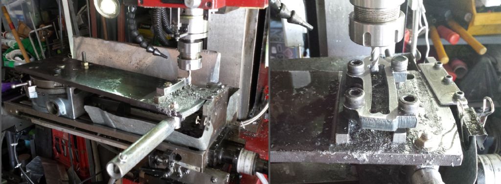
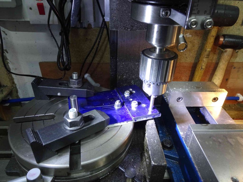
The task was to create the reversing gear (drawing a few posts back) which I was intending to do by mounting (superglue with tape method) my raw material on a long fixture, attach this to my rotary table and mill the outside through cartesian co-ordinates.
The idea is to drill / ream / mill the 6 and 8 mm locating / mounting / starting holes in X/Y co-ordinates and then switch to cartesian for the cutting.
My first attempt at this failed, mainly due to the superglue / tape chuck loosing grip (the tape side) and the piece slipping to the detriment of all.
I discarded this and tried again. This time I was going to bolt through the holes for the eccentric rods to keep it in place.
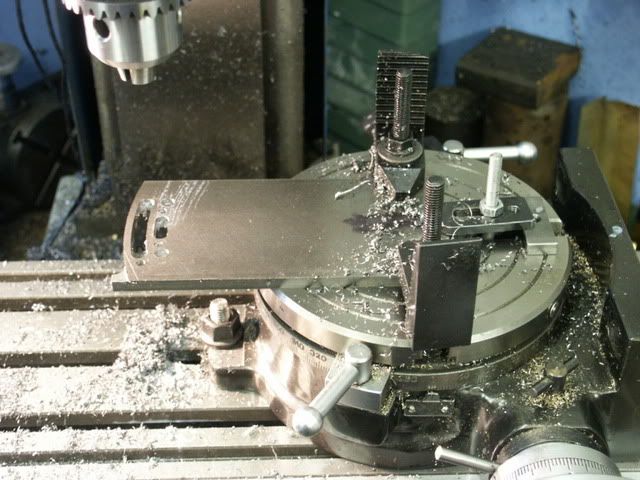
Here we have the aluminium fixture plate pinned to the centre of the rotary table and the first locating hole used to align the X Axis at 0 degrees.
Now, I bought the steel for the link from eBay advertised as mild steel, but that may have understated it's toughness. two 8mm HSS end mills pretty much refused to cut it and both had to be discarded. Also from eBay or equally suspect sources.
So I bit the bullet and ordered some quality mills from ARC. The 3 flute carbide cutter cut well (given that the first pass of the top had already been done by Mr. Dodgy mill). However, part way down the second leg the part started to vibrate something rotten and inspection revealed that the end mill had sheared.
IN a call with Brett at ARC he suggested that I was running this too slow and it was clearly user error, but despite this he is kindly sending me a replacement.
I carried on with a 2 flute HSS (again from ARC) which finished off nicely.
You can see the roughness from the original end mills along the top.
Next step was to mill the slot. In this case, I chose to follow some recommendations from Joe Pie and pre-drill (in my case with a slot dril) before a finishing cut.
This wasn't terribly successful, there was a lot of vibration (even with the table locked) and I had to finish off the slot by widening a bit.
Given all that had gone on I was reasonably pleased. I'd abandoned the idea of cleaning the ends with the rotary table and filed instead.
And then I took another look at the piece – spot the error?
Indeed! the slot goes right to the end and there is no hole for the control handle!
Argh!!!
At that point I stopped for the night and a nice cup of tea.
Now I have a question. Ignoring various machining errors, it seems to me that there is not enough meat around the slot and possibly around the eccentric rod holes.
The design has 3.5mm above below the 6mm slot. That should be 13mm, but in fact it is 11.9. The slot is actually about 6.3mm and the lower meat is only a bit over 2mm.
The design calls for the meat round the eccentric rod holes to be 2mm.
Firstly, I think I need to pay more attention to how I mill this out. I think I should probably rough mill 0.5mm outside where I want to finish and then take a finishing cut.
Secondly, I think that the meat needs to be bigger. I think 4mm round the slot and 3 round the holes would be better.
Finally, of course, I should avoid merging the slot with the control handle hole!
I think I might have a go at this with just some aluminium plate to get my measurements and skills up to scratch and then try it again.
I'll also have a couple of goes at different ways of doing the slot.
Any feedback on sizes (or technique) would be much appreciated!
Iain
15 March 2021 at 20:34 #534046 JasonBModerator@jasonb
For the outside radius I would use the full height of the cutter and take say 0.5mm passes and if that is OK go upto 1mm working in to the finished radius.
For the slot I would drill each end 6mm and then use a 5mm dia cutter to cut a central slot going down 1mm per pass and using the end holes to allow the cutter to be lowered, you can then move over say 0.25mm twice to finish each side to finished size
One thing I did see that may be causing vibration and short tool life is that you don't have enough of the shank in the collet, you should have all the weldon shank that can be seen in this photo inside the collet and some of the full round below it.

3.5mm either side should be OK, 4mm better. As for the holes then usual rule of thumb is to make the radius of the end the same as the hole dia so if they are 6mm holes use a 6mm radius so 3mm thickness of metal around the holes
Edited By JasonB on 15/03/2021 20:41:37
15 March 2021 at 21:08 #534048Iain Downs
Participant@iaindowns78295Thanks, Jason.
'For the outside radius I would use the full height of the cutter and take say 0.5mm passes and if that is OK go up to 1mm working in to the finished radius.'
Do you mean to cut 4mm deep (depth of the metal) but start 1mm outside the finished edge of the piece, or do you mean to cut 0.5mm – 1mm deep on the finished edge – hence 4 – 8 passes?
I think one of the problems was that when I saw that the carbide cutter was cutting nice, I cut to full depth (4mm + 1mm inside the aluminium fixture) which I think dragged the cutter into the work.
Iain
15 March 2021 at 21:49 #534055Nigel Graham 2
Participant@nigelgraham2I've found (well, was more likely advised) that cutting a slot to size is more successful if all the cut are in the same direction.
In other words, lift the cutter clear of the work at the end, and move the work back to the starting position for the next pass. Don't take too deep a cut in each pass. In that way any deflection of the cutter is always to one side. If you try cutting on the way back the cutter then deflects the other way, doubling the over-cut.
The fixture should not have dragged the cutter anywhere. That suggests something not quite rigid enough.
'
I've a specific interest here as I need make two pairs of expansion-links (one pair will be stored away until.. but may as well make them all in the same set-up). I once cut a long keyway in a replacement arbor for a milling-machine, using a straight-flute cutter, very successfully… I've not found any such milling-cutters listed anywhere, and have a sneaking suspicion that it was actually a wood-working router-bit, though I did not know that at the time! I used a fairly high speed, shallow cuts, slow feed (manual) … and a lot of patience.
16 March 2021 at 07:01 #534089 JasonBModerator@jasonb
Iain, For the outer radius set cutter to just below bottom of work so you are cutting full height and then move in 0.5 -1.0mm in ever decreasing radii. so first cut will just knock off the two corners, second a bit more and the last one or two will be a full arc from one side to the other.
My suggestion of using a smaller cutter for the slot and then a couple of light passes off each side will eliminate any of the deflection problems Nigel mentions.
Edited By JasonB on 16/03/2021 08:01:18
21 March 2021 at 19:19 #535317Iain Downs
Participant@iaindowns78295Will our intrepid novice manage to cock up his reversing link for the third time? Will any more carbide end mills suffer?
Read on to find out!
So I had a good deal of advice on this. Firstly I made the meat of the link a bit thicker. Then I tried to approach the outside and the slot a bit more gradually. Finally, I ran my carbide mill at top speed!
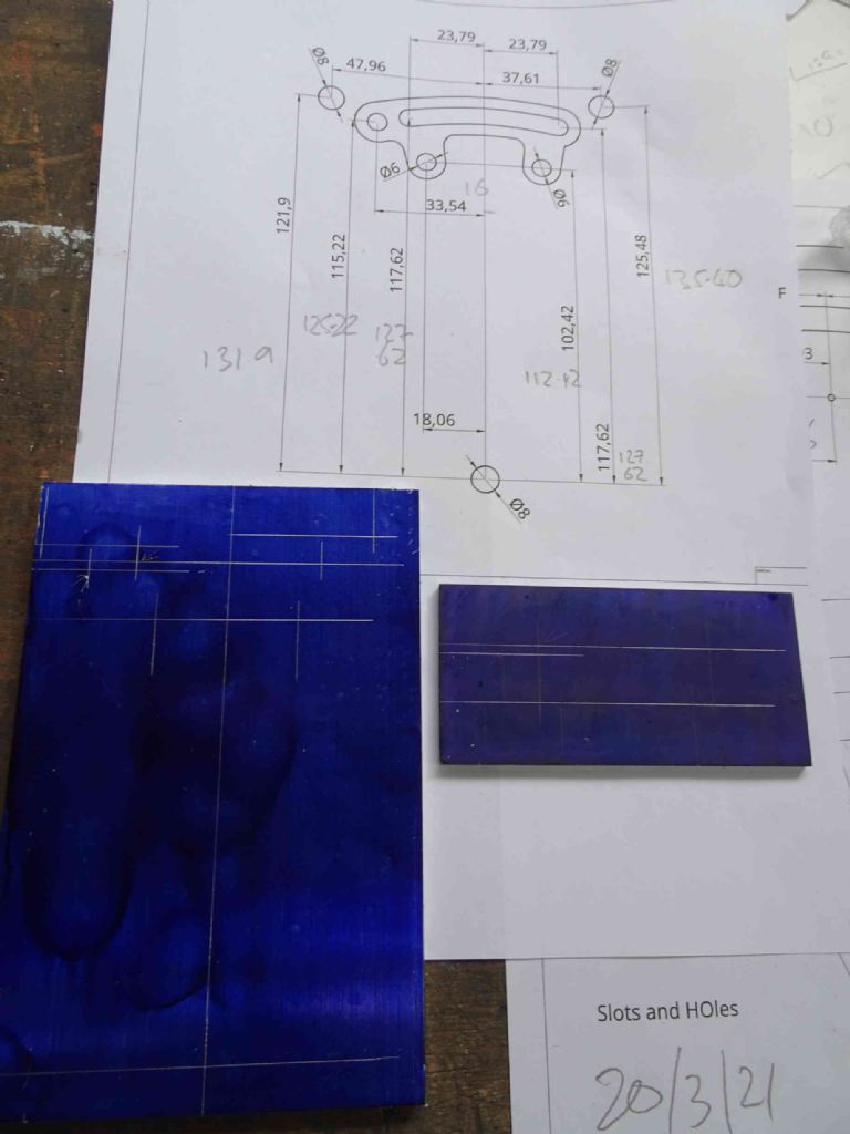
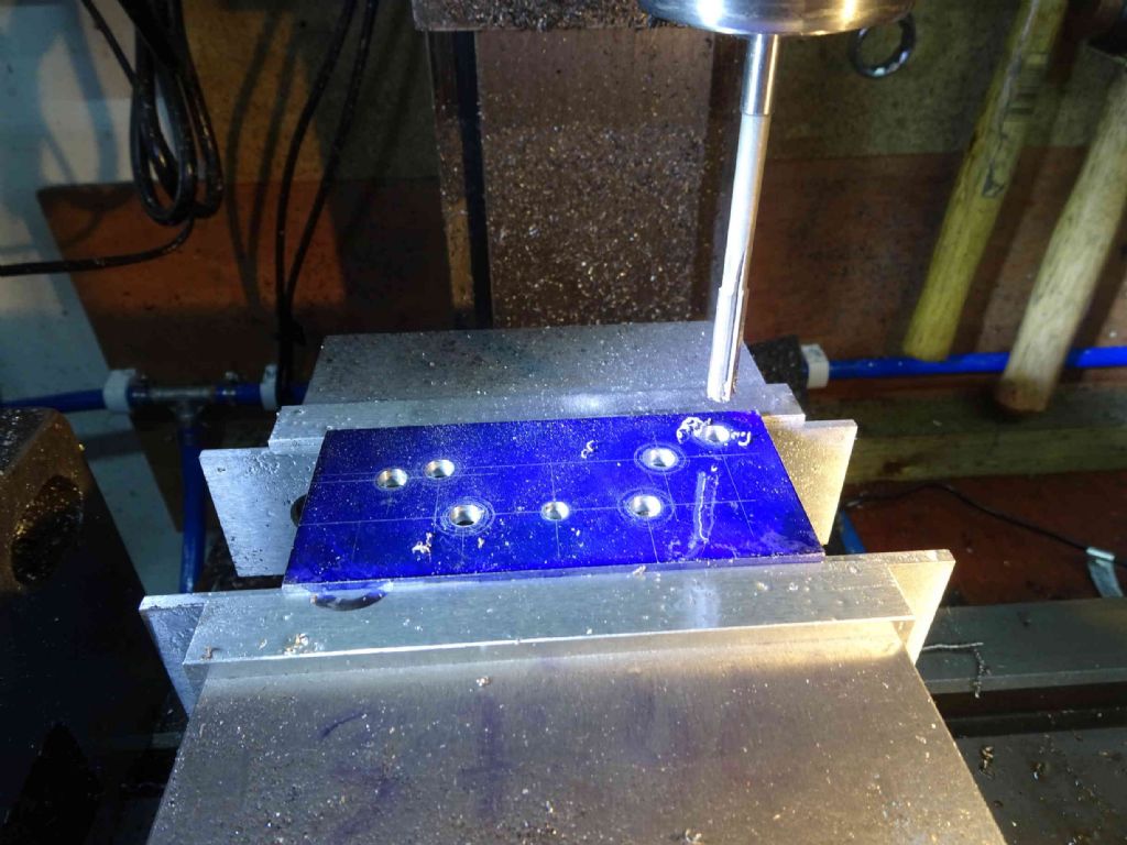
I took a different and more daring approach to this build. I decided that, rather than bond the fixture and piece and drill my marks through, I would drill and ream them separately and bolt together – no superglue chuck for this boy.
I started by marking them out on a surface table – not that I intended to use this to drill – I have a DRO and I'm not afraid to use it!
Here I am having reamed out the salient items on the piece
I was delighted (not to say a little surprised) that all my pins could push through both items at once!
Here we are (again) aligning the item up on the rotary table at zero degrees.
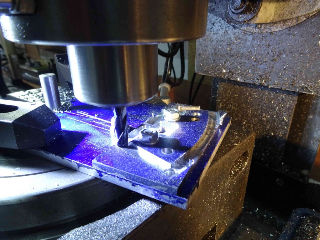
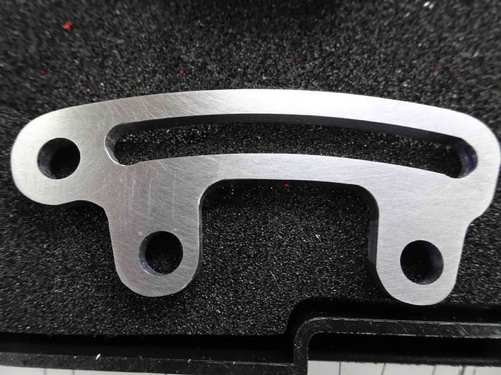
for the outline I used an 8mm carbide end mill running at 2200 rpm (thanks for the chance to try again Brett of ARC!). The first cut was 2mm outside the piece and 2mm deep, the next cut the same at a bit over 4mm to cut through
I then took 2 passes each 1mm closer to the finish dimensions. There was a bit of rattle at the outside arc which is quite a bit outside the support of the rotary table, but the finish was still decent.
Having done this, I think cut the slot. first cut in 1mm increments down the centre with a 4mm hss end mill. Then two passes of 0.25mm to the finish dimension. According to my calipers the slot is 6.03mm wide so I made it 1 though oversized. Amazing!
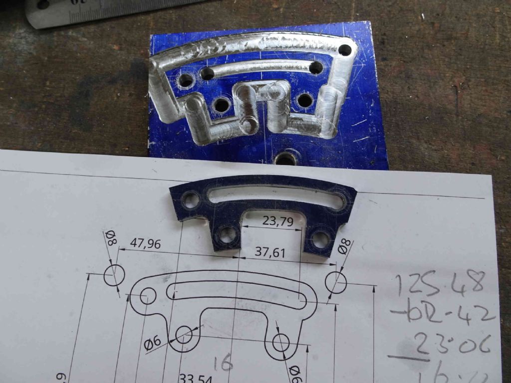
Here we have the raw piece, the fixture and the drawing and, finally, this is what it looks like after some tidying up on the belt sander and a bit of time with some 320 grit .
The astute reader will notice that the slot is a little higher than the end holes and that the eccentric rod holes aren't central to the meat of the legs.
Despite that I'm very happy with this piece and AT LAST, I can move on to another part.
Iain
23 April 2021 at 09:09 #541192Iain Downs
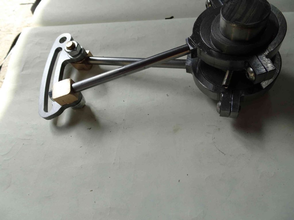
Participant@iaindowns78295These last few days / weeks I've been working on connecting the eccentric straps to the stephenson's link.
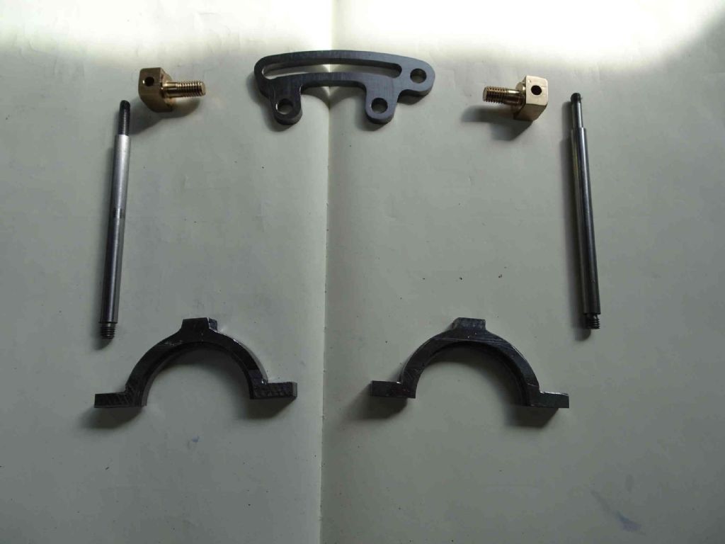
Not too many pictures I'm afraid, but..
Here are the bits
And them (temporarily) connected
I@ve found that the straps no longer run quite as freely in the eccentrics. Not sure why that is – possibly some grit or could be orientation. I will have to tidy that up.
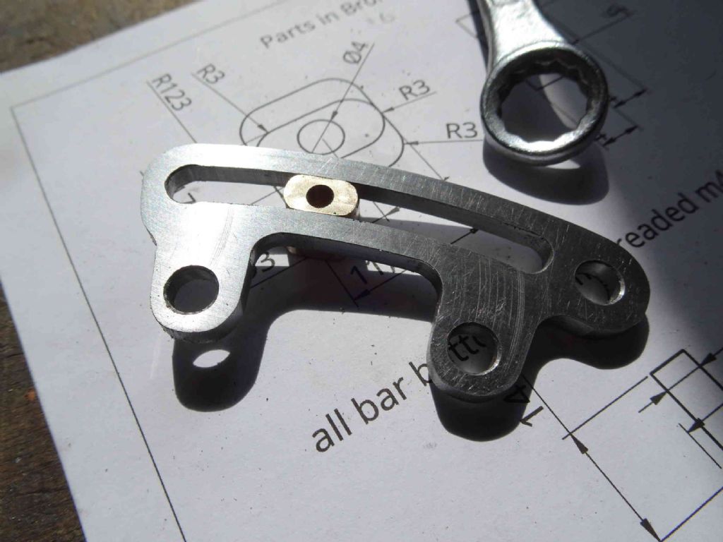
Also in this series of workshop trials, I've made the nut that connects the upper eccentric rod to the valve gear.
This was quite a complicated bit of work and here's what I did.
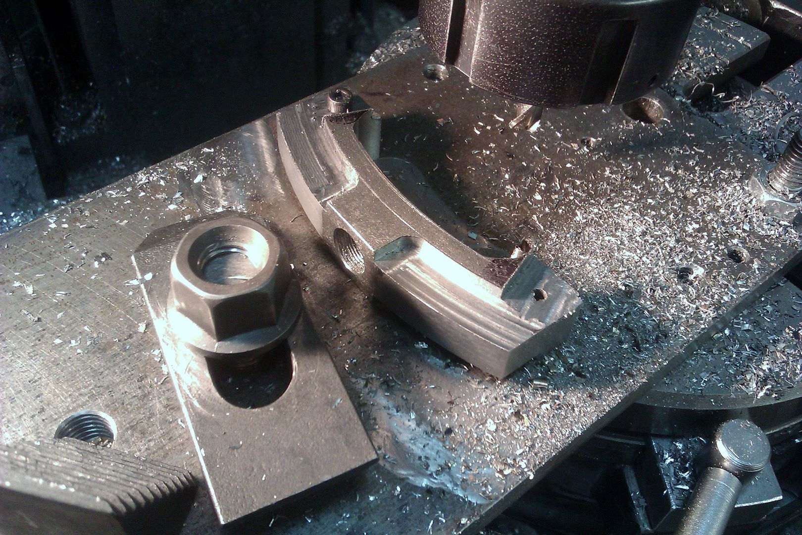
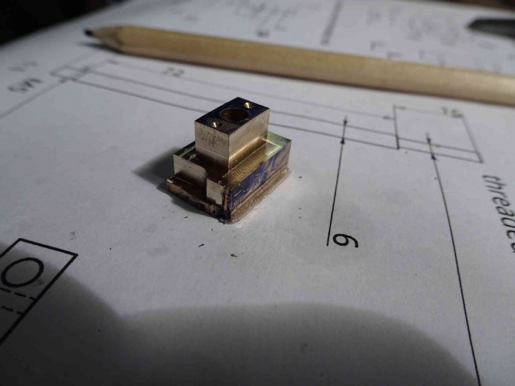
Firstly square up a piece of bronze. The final item is about 12mm square with the spigot being 12mm long and 6mm thick, but faintly curved along a 120mm radius. The centre hole for the axle for the upward part of the system is 4mm.
So I have a piece 12 x 20 x 20 (or so). My intent was to use a superglue chuck on a fixture on the rotary table. I figured that the longer the piece the better the adhesion. The stock was 2mm to high at the top and 2mm too deep at the bottom to provide a raft for holding and some excess on the top to clean off.
So with my squared stock I drilled and reamed a 4mm hole in the centre and did the same on my fixture plate (at 120mm out from the axis. A 4mm pin and a try square oriented the piece whilst the superglue set. Next day a light tap drove the pin out.
Cutting the curves (and try fitting as the width approach 6mm worked well. Next I took the length of the spigot to 12mm. This also worked well.
The I started to take the based down to 12mm and took too aggressive a cut and, 'pop' off came the piece from the fixture!
And it was going so well!
I'd originally intended to cut the round edges on the rotary table, but I gave up on that idea and, having trimmed the remaining top and bottom and sides in the mill, I (rather gingerly) rounded the ends with a small file. It's not something clickspring would be proud of, but it's good enough for me!
What I found interesting, was that the nut no longer fit the slot in the reversing link. I think that this is because I squeezed the base to hard in the vice in and it mushroomed. However a few strokes of the file in the slot and it runs nicely now.
Next step is the valve chest and D valve. Once that;s done I can check that the bits fit together and I'm nearly there!
Iain
23 April 2021 at 09:18 #541196Iain Downs
Participant@iaindowns78295I'm not leaving the work reporting behind for a plea for help.
Steam lines.
I've not yet worked out how to get steam into and out of the valve chest.
There's actually a fair amount of meat in the cylinder to the exhaust port and the valve chest wall so I could put in a threaded hole.
Alternatively I could make / buy a boss and bolt it to the wall. In so far as I have a design source for this, it's the stuart 5A (being around the same size). That has bosses with half inch (12mm) or 3/8 (8mm?) 26 tpi (1mm?) threaded insides.
Having recently discovered compressed air, I was thinking of 1/4 BSP which is roughly in the same area.
Then how do I connect steam (/air) to it.
I would generally prefer to work in metric but a set of 1/4 BSP tap / dies are attractive now I have air in the shed.
Final question (for now). Can I use PTFE tape as a seal or would it melt with live steam?
Many thanks
Iain
23 April 2021 at 09:45 #541207 JasonBModerator@jasonb
The flanges are a bit easier to use as if you need to separate a run of pipework from the engine it is easy to undo a flange but not so easy to unscrew convoluted pipe runs. You should be able to shape up flanges from flat stock or even the end of round bar.
On the larger engines I use BSP then it's simple to screw in an air fitting. Yes PTFE tape will do and easy to take apart to change from steam to air
-
AuthorPosts
- Please log in to reply to this topic. Registering is free and easy using the links on the menu at the top of this page.
Latest Replies
Home › Forums › Stationary engines › Topics
-
- Topic
- Voices
- Posts
- Last Post
-
-
After all these years … I fell for a scam :(
Started by:
 Michael Gilligan
in: The Tea Room
- 1
- 1
-
8 July 2025 at 09:01
 Michael Gilligan
-
Square end on round stock – Milling?
Started by:
Roger TheShrubber in: Workshop Tools and Tooling
- 13
- 16
-
8 July 2025 at 08:59
IanT
-
Bosch PBD 40 bearing upgrade
Started by:
th1980 in: Manual machine tools
- 2
- 3
-
8 July 2025 at 08:56
th1980
-
Chester Champion, warco ZX15 drawbar
Started by:
martian in: Manual machine tools
- 4
- 4
-
8 July 2025 at 08:34
 JasonB
-
Angle grinder woes
Started by:
Speedy Builder5 in: Workshop Tools and Tooling
- 3
- 3
-
8 July 2025 at 08:31
 Fulmen
-
How many spokes do I really need?
Started by:
 Fulmen
in: Related Hobbies including Vehicle Restoration
- 6
- 14
-
8 July 2025 at 08:27
 Fulmen
-
Boiler Design – issue 4765
1
2
…
7
8
Started by:
Charles Lamont in: Model Engineer & Workshop
- 26
- 182
-
8 July 2025 at 06:44
 MEinThailand
-
Hi, new member from Liphook,Hants
Started by:
Chris Rushton in: Introduce Yourself – New members start here!
- 1
- 1
-
8 July 2025 at 04:01
Chris Rushton
-
A grasshopper of unknown vintage
Started by:
mikemunson in: Stationary engines
- 4
- 4
-
7 July 2025 at 23:43
Nigel Graham 2
-
Old plastic handled screwdrivers
Started by:
 Dave Halford
in: Workshop Tools and Tooling
- 7
- 7
-
7 July 2025 at 23:29
 peak4
peak4
-
Maisie lubricator
Started by:
ferroequinologist in: Locomotives
- 8
- 12
-
7 July 2025 at 23:23
Nigel Graham 2
-
motor and switch wiring Myford ML7
Started by:
1957jmh in: Workshop Tools and Tooling
- 1
- 1
-
7 July 2025 at 22:49
1957jmh
-
Herbert B drill – a question and a curiosity…
Started by:
gerry madden in: Manual machine tools
- 4
- 7
-
7 July 2025 at 21:15
gerry madden
-
Bridgeport Series 1, table power feed.
Started by:
Daedalus in: Manual machine tools
- 1
- 1
-
7 July 2025 at 21:04
Daedalus
-
File backup to external hard drive, incremental etc?
Started by:
Peter Bell in: The Tea Room
- 8
- 12
-
7 July 2025 at 20:47
ChrisLH
-
Bridgeport ways and wear
Started by:
inline in: Manual machine tools
- 5
- 15
-
7 July 2025 at 20:34
 David George 1
-
road registration and traction trailer.
Started by:
RRMBK in: Traction engines
- 8
- 12
-
7 July 2025 at 19:36
here again
-
Twin Engineering’s heavy mill/drill quill removal
1
2
Started by:
Martin of Wick in: Manual machine tools
- 11
- 31
-
7 July 2025 at 17:18
 Nicholas Farr
-
A Persistent Scam
Started by:
Chris Crew in: The Tea Room
- 7
- 8
-
7 July 2025 at 17:05
Trevor Gale
-
Readability / clarity in new combined magazine
1
2
Started by:
Trevor Gale in: Model Engineer & Workshop
- 18
- 28
-
7 July 2025 at 15:53
 Russell Eberhardt
-
Pragotron Slave Clock
Started by:
renardiere7 in: Clocks and Scientific Instruments
- 7
- 17
-
7 July 2025 at 12:32
 Robert Atkinson 2
-
Motorised Adept No. 2 Shaper
1
2
Started by:
William Ayerst in: Workshop Tools and Tooling
- 10
- 28
-
7 July 2025 at 11:43
 Bazyle
-
Starrett and other tool manufacturer wood boxes
Started by:
Ian Owen NZ in: Workshop Tools and Tooling
- 12
- 18
-
7 July 2025 at 09:56
 Mark Easingwood
-
What Did You Do Today 2025
1
2
…
7
8
Started by:
 JasonB
in: The Tea Room
- 33
- 176
-
6 July 2025 at 21:35
Nigel Graham 2
-
Speed camera
1
2
3
Started by:
 David George 1
in: The Tea Room
- 24
- 61
-
6 July 2025 at 21:05
old mart
-
After all these years … I fell for a scam :(
-
Latest Issue
Newsletter Sign-up
Latest Replies
- After all these years … I fell for a scam :(
- Square end on round stock – Milling?
- Bosch PBD 40 bearing upgrade
- Chester Champion, warco ZX15 drawbar
- Angle grinder woes
- How many spokes do I really need?
- Boiler Design – issue 4765
- Hi, new member from Liphook,Hants
- A grasshopper of unknown vintage
- Old plastic handled screwdrivers


 and start at 0 degrees.
 That's usually enough to unearth lost things.