Steam Engine Number One
Steam Engine Number One
Home › Forums › Stationary engines › Steam Engine Number One
- This topic has 207 replies, 23 voices, and was last updated 7 February 2022 at 12:58 by
 Andy_G.
-
AuthorPosts
-
1 June 2019 at 18:21 #412102
 JasonBModerator@jasonb
0.5mm pitch is probably a bit finer than I would have gone, 1.0mm or 0.75mm on a 10 or 12mm dia would be about right. Reducing to M10 on the end of the 12mm rod will be OK strength wise.
I'd also drill and tap a bit deeper than you have it shown on the drawing above, say 18mm which will just miss thecrosshead pin hole.
3 June 2019 at 08:25 #412333Iain Downs
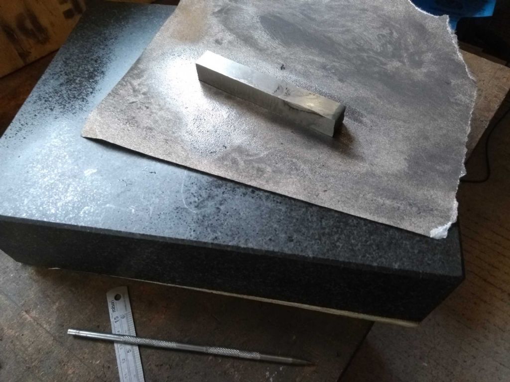
Participant@iaindowns78295Paul – I forgot to mention that I took your advice on the key. I found a piece of 4mm square in my bits box – actually part of a hook of some kind and I have no idea where it came from. I cleaned it up and lapped it (300 grit paper on a surface table) and fitted it to size. It's working so far.
Hi, Jason – the drawing is of a soldered assembly – I've not updated it, but will do so before completing.
Iain
8 June 2019 at 08:41 #413209Iain Downs
Participant@iaindowns78295I've been Multi-tasking again, but to save confusion I shall separate the work as if I did it in a linear fashion! The reason for multi-tasking was that I ordered some specific drills for the crosshead bearing hole and taps for the piston rod. I only had millimeter drills above 6mm and I didn't want to try reaming a 10mm hole on a 9mm drilled hole!
So the side work was to continue the top cylinder cap.
I found this strangely difficult most of the way through. For the main part I was using a carbide tool which has served me well, but I felt it wasn't cutting right. I swapped ends and tips a couple of times but nothing seemed to make it go nicely. I tried speeds from 300 to 600. What I was seeing varied, so I was probably doing a lot of different things wrong!
Sometimes I got a kind of ripple effect on the iron. I suspect some kind of vibration was causing this and I think I was hearing a whine whilst this was going on.
When cutting along the face, there was an area around 25-35 mm from the centre where the lathe struggled and I saw a different texture to the machined part. It was also in the area that the lathe was most likely to stall. Incidentally for the main part I was only able to take 0.25mm cuts and that fairly gingerly until nearer the centre.
Towards the end of the job, I thought I'd try out an HSS tool. This really didn't work. In fact the only effect was to wear down the face and polish the iron! I don't think the geometry of the tool was right for the face. However, when I put the carbide tool back on, suddenly everything was working nicely! I could even take 0.5mm cuts (albeit with some care).
I have two theories. One is that the ripple of the previous cut caused the tool to vibrate which added ripple in this one. By polishing the surface with the HSS tool, the ripple was removed.
The second is that I'd (by chance) got the alignment of the indexed tool just right at the end for it to cut cleanly.
Ah, the mysteries of engineering!
However, that's the end of the dull stuff. Here are some pictures.
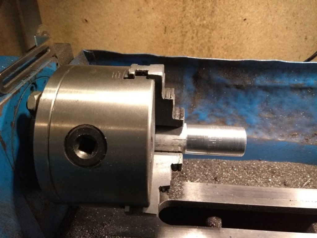
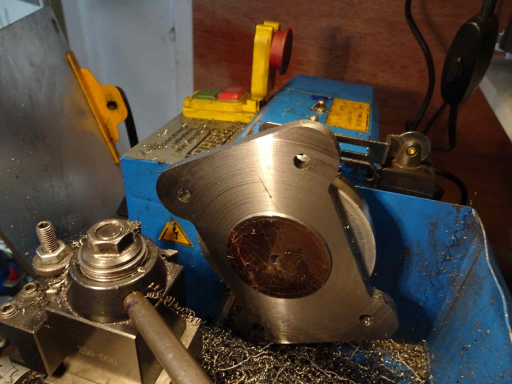
When I turned the piece round to hold the stub in the 3 jaws, I wanted to make sure that it was secure, so I set a centre against it.
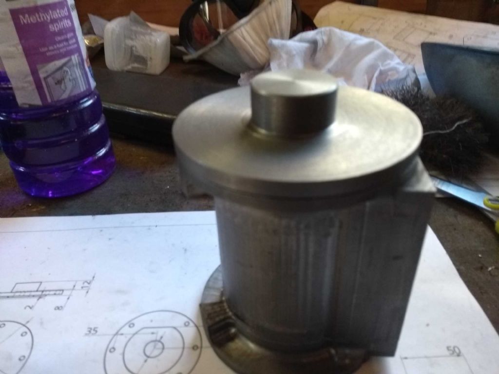
Then turned the part down to 80mm and made sure it matched the cylinder (it turns out that one end external diameter is about 0.1mm smaller so I've engraved T on the side of the cylinder to make sure I get it right.
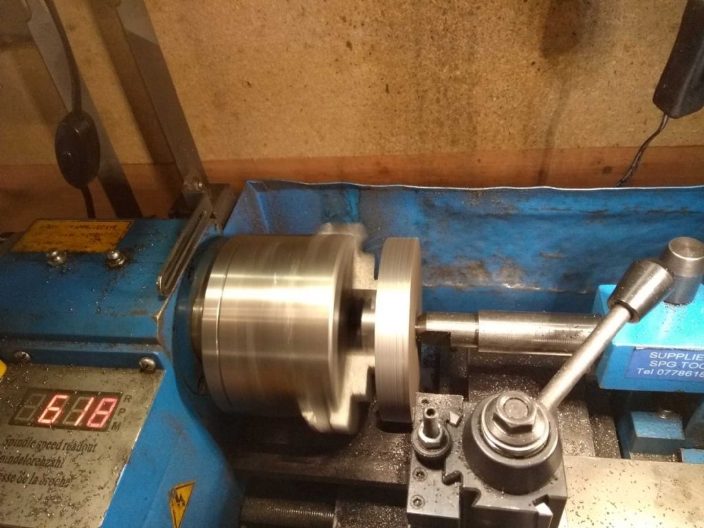
Following that took the thickness down to 7mm, and removed the centre and turned down the nun.
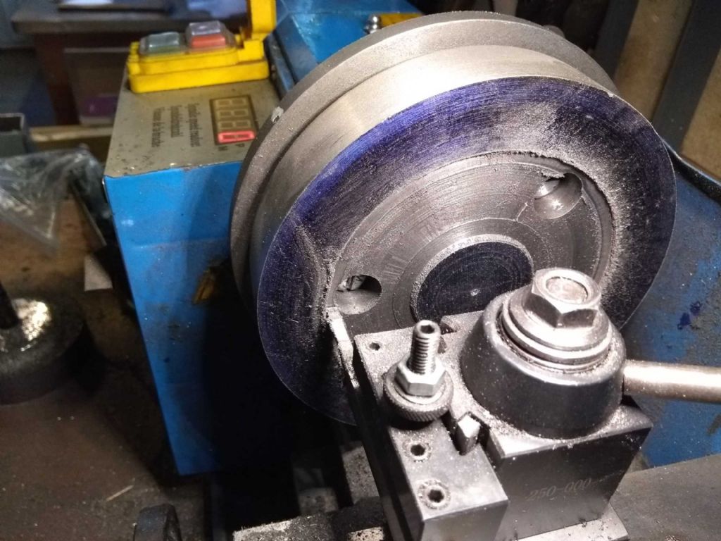
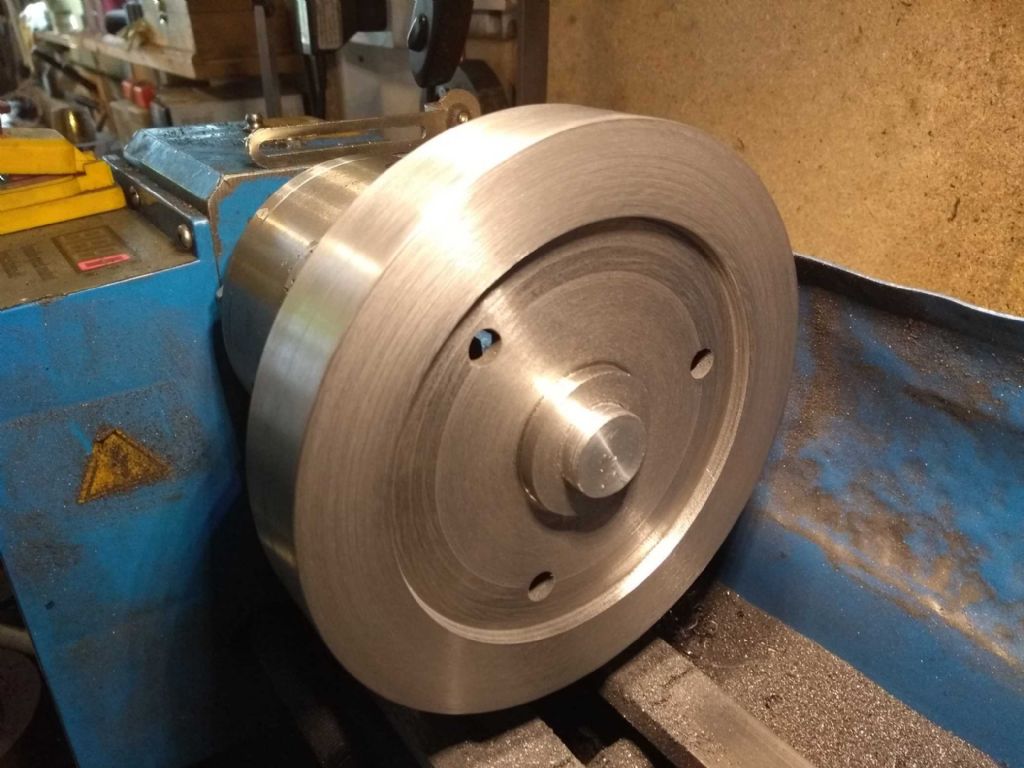
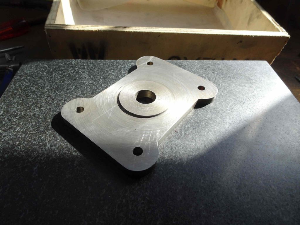
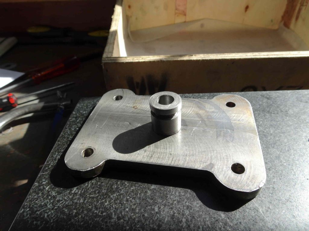
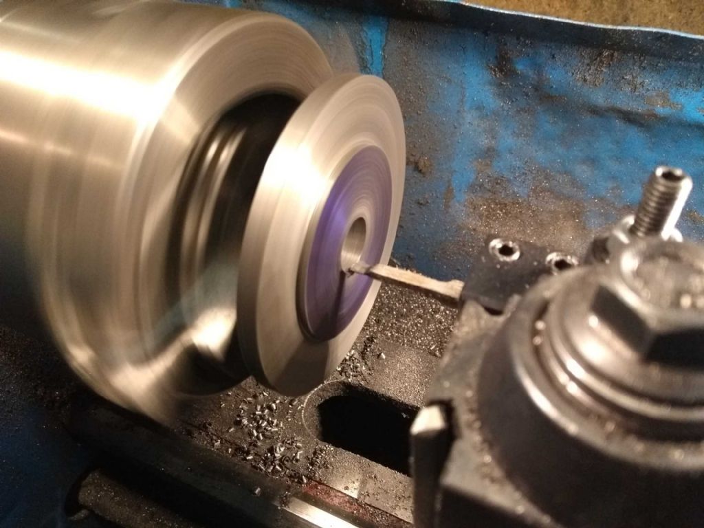
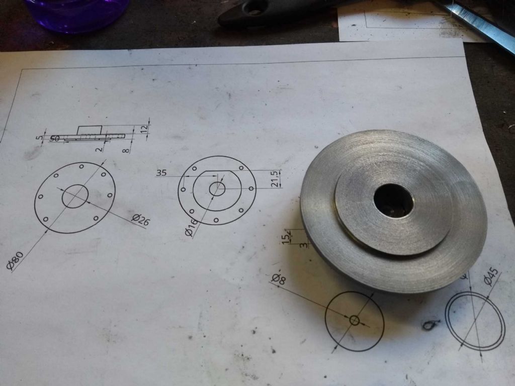
I then took 2mm of the face up to 50mm leaving a 2mm raised locating area. This was taken down to a measure 50 point something and then I used try and fit to get a perfect registration with the cylinder.
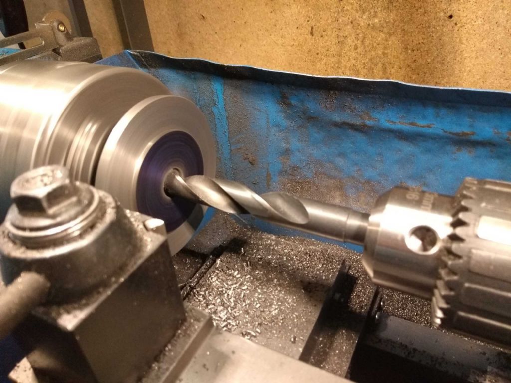
You can also see here the drilling out of the centre to allow the nut securing the cylinder to have some space.
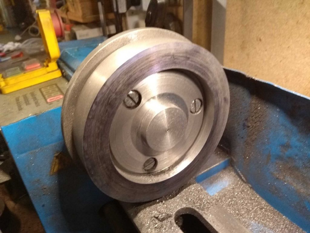
And then trimmed to size.
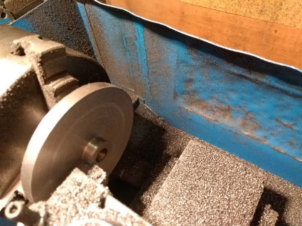
And here we have the result.
Now it's time for more excitement; recycling to the tip and an Aldi shop. Perhaps they'll have some nice tools today ….
Iain
17 June 2019 at 20:58 #414734Iain Downs
Participant@iaindowns78295Back to the Well, I've had a bit of a run at work on the con rod assembly – which is nice, but it's going to make this post a bit of an Epic…
And it will be subtitled, 'Measure Twice, cut … Oh Bugger!'.
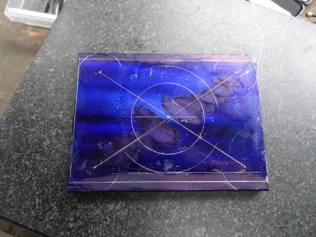
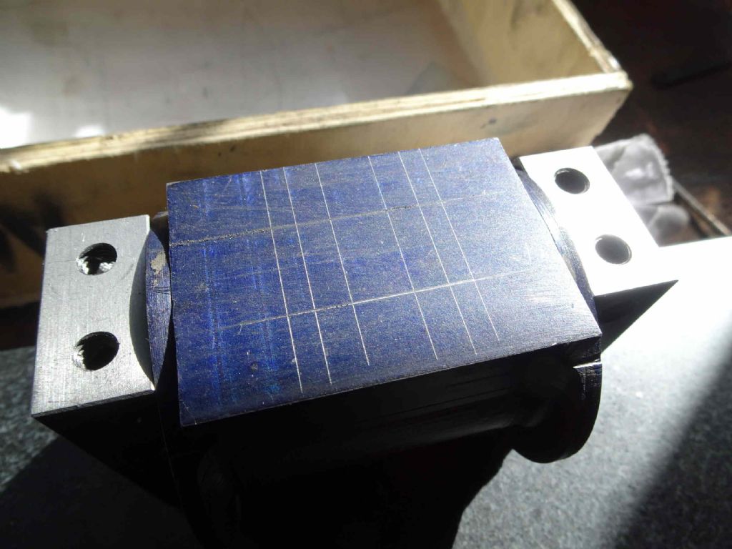
You see, the cross head is basically L shaped. So I marked out where the L should be and then in a stupor of insanity decided I'd got the wrong end and marked again. Fool! It turns out I was right the first time. I started cutting and then had a moment. So I measured for a third time and compared to the drawing, said some bad words and took stock.
It turns out (fortunately) that I'd not gone to far with the cutting and was able to re-mark and carry on. In the drawing below you can see one of the false lines near the top of the G Cramp.
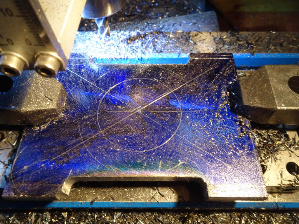
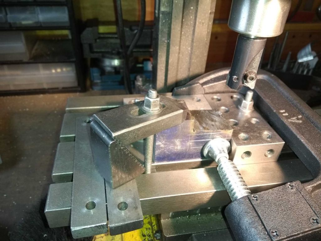
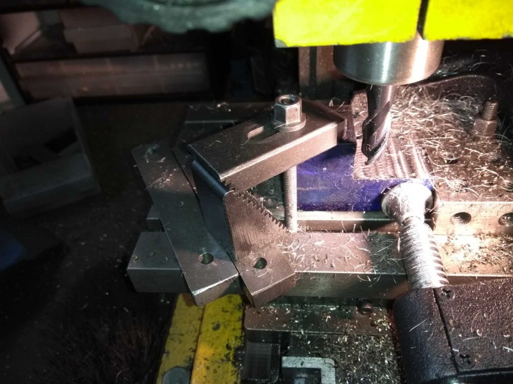
Although I took the bulk off with the face mill, I finished up to the edge with an end mill and trimmed the bottom at the same time.
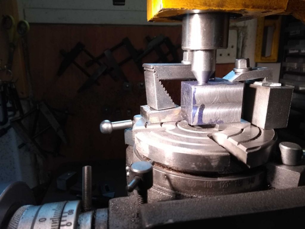
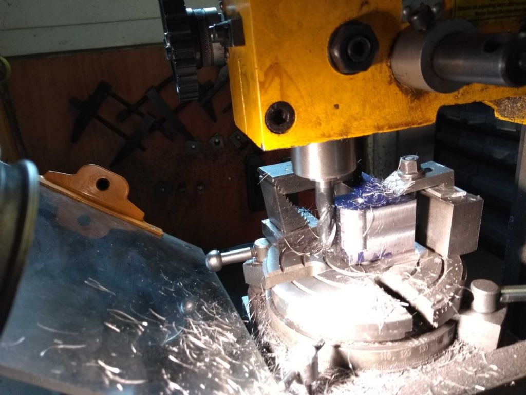
Next was to make the radius for the bottom of the cross head. What I do here (are reported earlier) is to centre the rotary table on the mill and then centre the work item for clamping with a centre in the mill spindle.
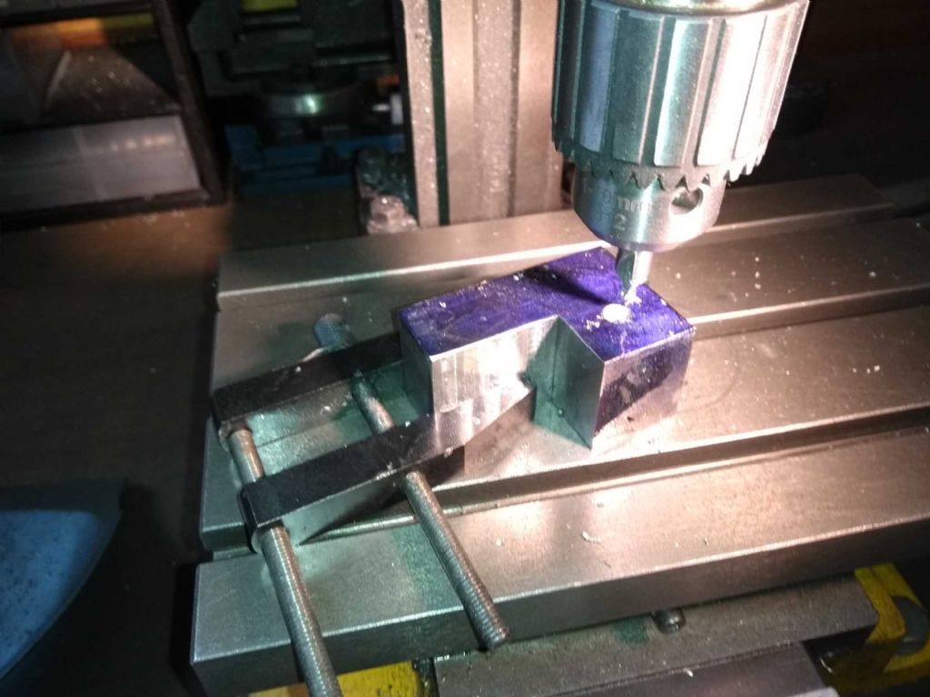
Here I centre drill the part
And the centre
And then on with the milling
In this operation, the part moved (clamping not tight enough), but I spotted it before it was unrecoverable. Sadly in the process I grabbed an Y which I should have grabbed a turn and took a bit out of the side.
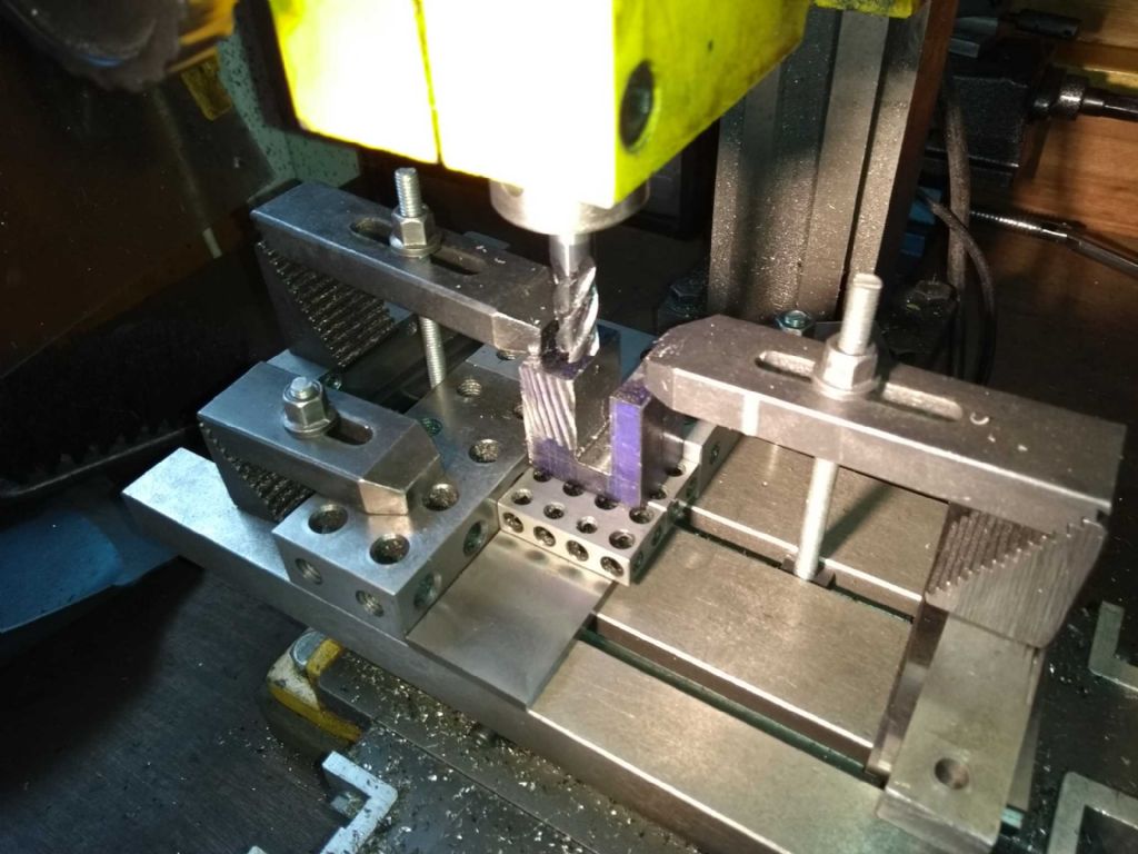
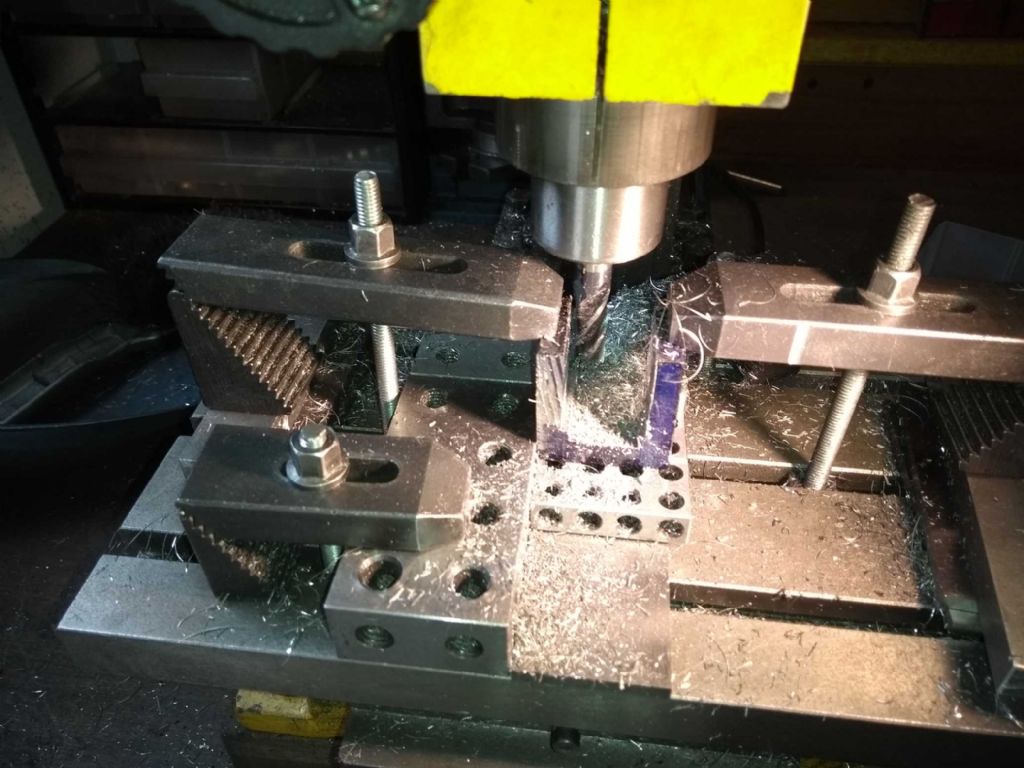
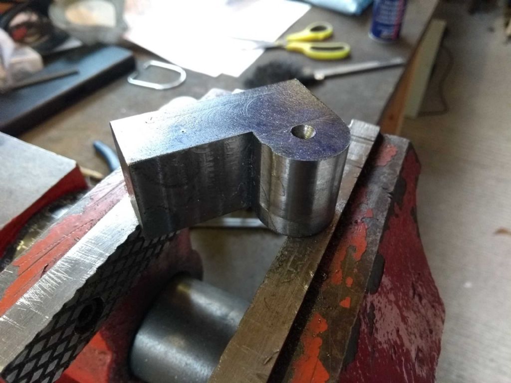
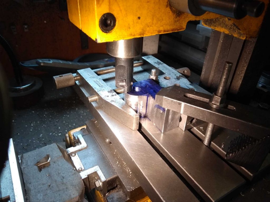
Next was to take 5mm of either side of the cross head proper
As follows
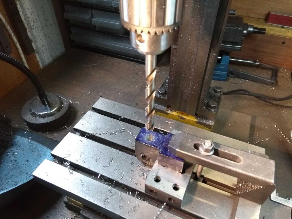
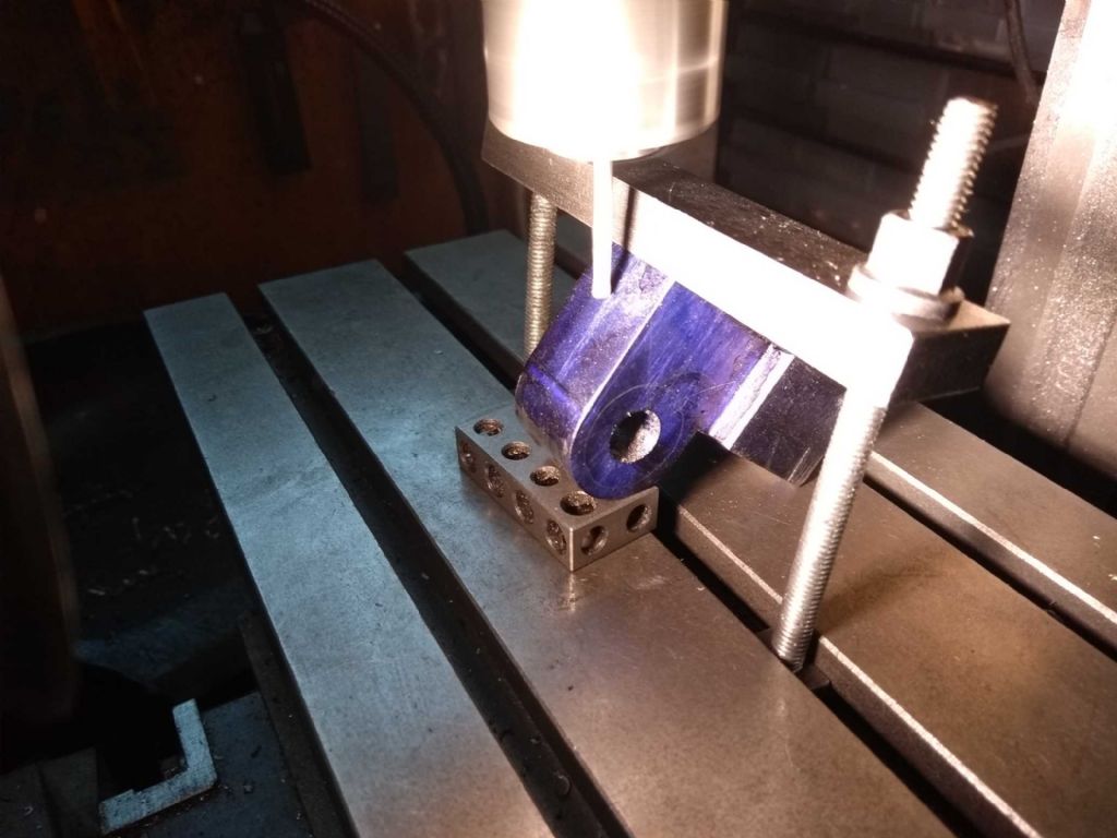
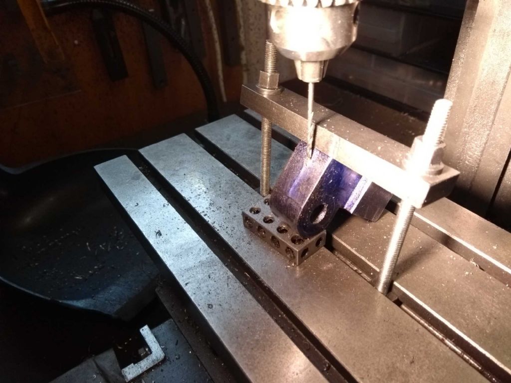
The shot above is also the set up for drilling the hole for a 10mm x 1mm threaded hole (threading not yet done, but tap has arrived!).
I drew up a design for the oiler hole, but when I looked at the part I found an easier way of getting something good enough (I hope).
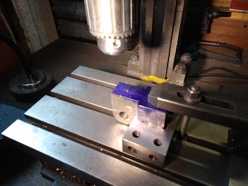
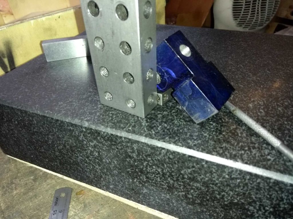
As you can see just resting the part on the surface table leaves a perfectly good oil route as a vertical. So I marked that out, clamped the piece and milled a small hollow. Not shown here is that I ground a small groove in the clamping plate to keep it in place.
The drill through
It turns out that I'm being too loquacious and so need to stop here or the system tells me off.
More in a moment!
Iain
17 June 2019 at 21:02 #414735Iain Downs
Participant@iaindowns78295And to carry on …
The next operation on this part was to be to mill a slot for the guide. However, before I got to that I wanted to clean up the rod I'd got for the guide. It turns out (I seem to be saying that a lot in this post!) that the 15mm square bar I bought at the show is a tad under 16mm. Rather than attempting to mill it down to what I'd drawn, I thought I'd just make the slot a little bigger.
However, the first step was to final and emery it reasonably square, straight and smooth.
Back to the Mill and cutting the slot. As I got close to 15.8 mm I took very fine cuts and started to try the guide.
I still need to cut the bronze for the cross head guide bearings, but I'd had enough of this piece. It's probably the most complex piece of machining I've ever done and surprised I got (nearly) to the end with out breaking it!
So I took a nice refreshing rest on the lathe.
This was to machine the bronze pin which would act as an axle / bearing for the cross head.
As usual, I had a bit of metal too big and needed to lose most of it
 .
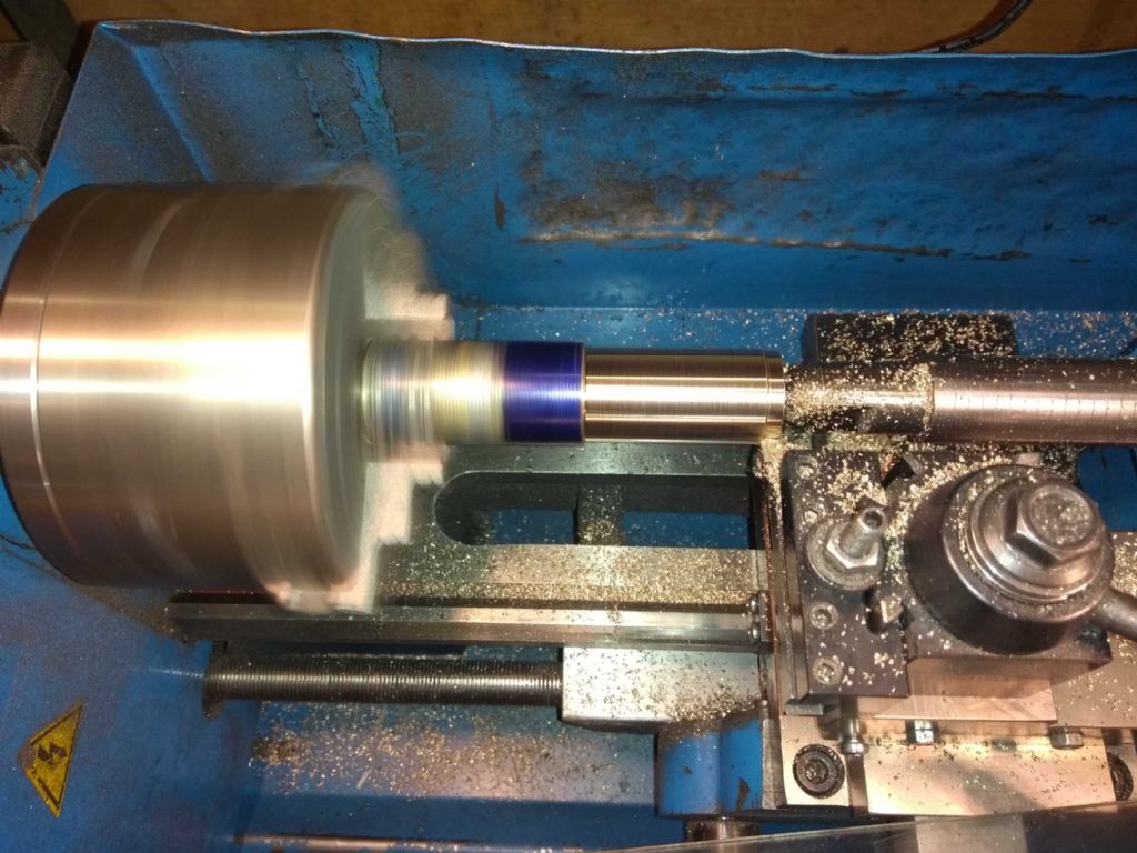
.a 25mm piece of bronze which needs to be turned down to 10mm, Mind you with a 20 mm head on .
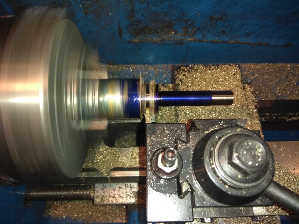
And here I part it off. Parting of bronze after cast iron is such a pleasure!
You may notice by the way the profligate use of marking blue in this post. The marking blue was a purchase at the show and a welcome one. I've been using a sharpie (per advice in this forum) which is all very well when you don't want to do much. But a few wipes with cutting oil and it disappears leaving you none the wiser where to cut. This stuff stays on very nicely, but still can be cleaned off with a but of meths.
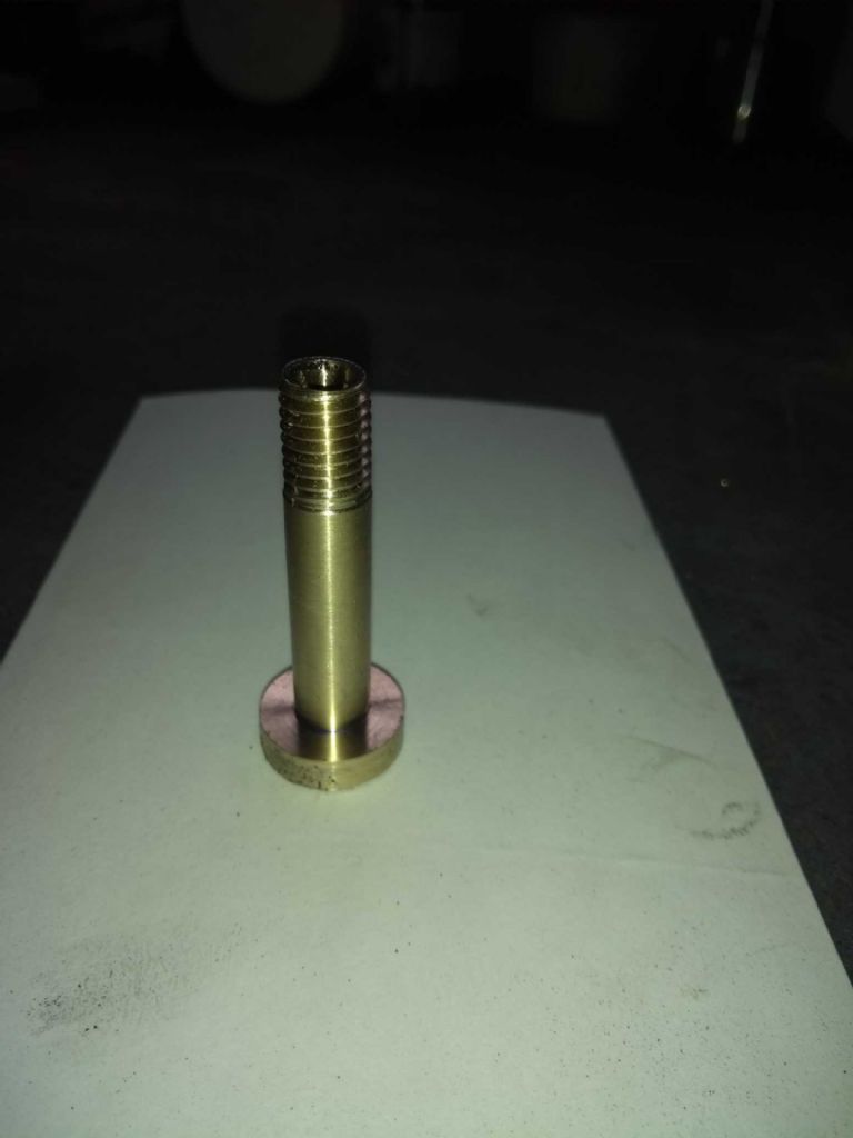
And here is the finished product after cutting a thread for the bolt.
I was originally going to file a head on this, but it seems a shame to take away the purity, so I may get my slitting saw out instead.
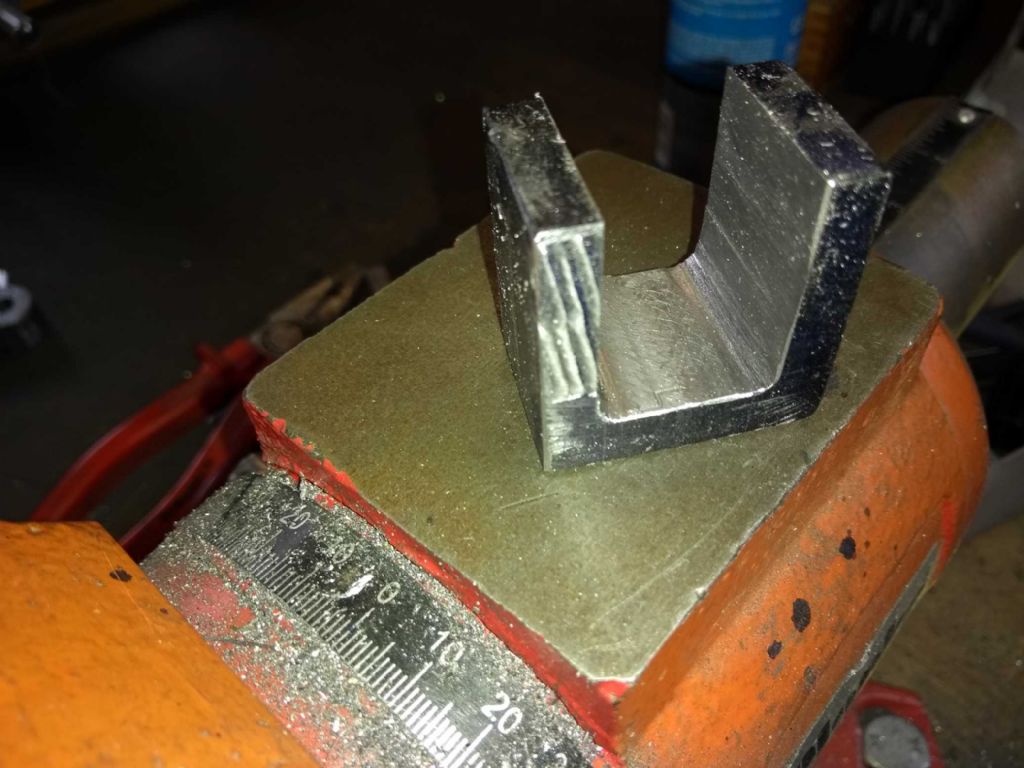
Never fear! The end is near! Only a little bit to go and this is the bit that goes below the cross head. I've no idea what people who have a clue call it so I've called it the cross head con rod. The bit tha the pin above connects to the cross head and which then goes down to the crank.
The main lesson from this is to clamp better.
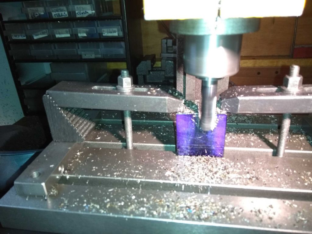
Here was my first clamping arrangement.
It survived about 5mm of cuts and then the cutter caught, then clamps went sideways and the motor quite. Just the overload light and a pretty common affair with this build.
A bit more thought and care ended up with this.
You can see on the left of the piece where the cutter went mad on it.
And as you can see above this arrangement meant I got to the end with no blow ups. Also I could position the piece back accurately when I took it out to measure the base thickness.
The observent will notice little squares at the base of the cut. My intent was to finish the cut with a ball nose cutter to provide relief. Sadly, I'd not taken into account the length the bit would have to stick out and the (carbide) tool went was part way through one side.
This left me to finish it off with files with the result below.
It still needs a bit of cleaning up, but it's getting there!
Iain
18 June 2019 at 06:58 #414774 JasonBModerator@jasonb
Progressing well, keep up with the posts.
Will have to see how well that bronze pin holds up when you start running.
For the future a part like the conrod end two holes can be drilled first to get the corner radius, you can even stitch drill along the bottom and then saw down the sides to get most of the waste out before milling.
24 June 2019 at 20:52 #415981Iain Downs
Participant@iaindowns78295Hi, Jason (and others, of course).
Today I had a bit more soldering practice and that turned out well. What I'm struggling with now is how to hold the parts of the con rod (big end connector, rod and cross head connector) in such a way that they end up at right angles.
I've thought of pinning them (or the second one to solder) or trying to make some sort of rig. I'm not convinced that just standing them up and hoping they don't move is the right approach!
I did think of drilling the corners as a starter but rejected the idea for no good reason I can now bring to mind…
Next time…
Iain
10 July 2019 at 19:57 #418228Iain Downs
Participant@iaindowns78295This last week or so has been about the flywheel.
As usual, I wouldn't have done it this way if I'd thought about it….
I'd bought a 1 inch thick piece of 6 inch diameter cast iron at the doncaster show for the flywheel, think that this was about as big a piece as my 7×14 would cope with.
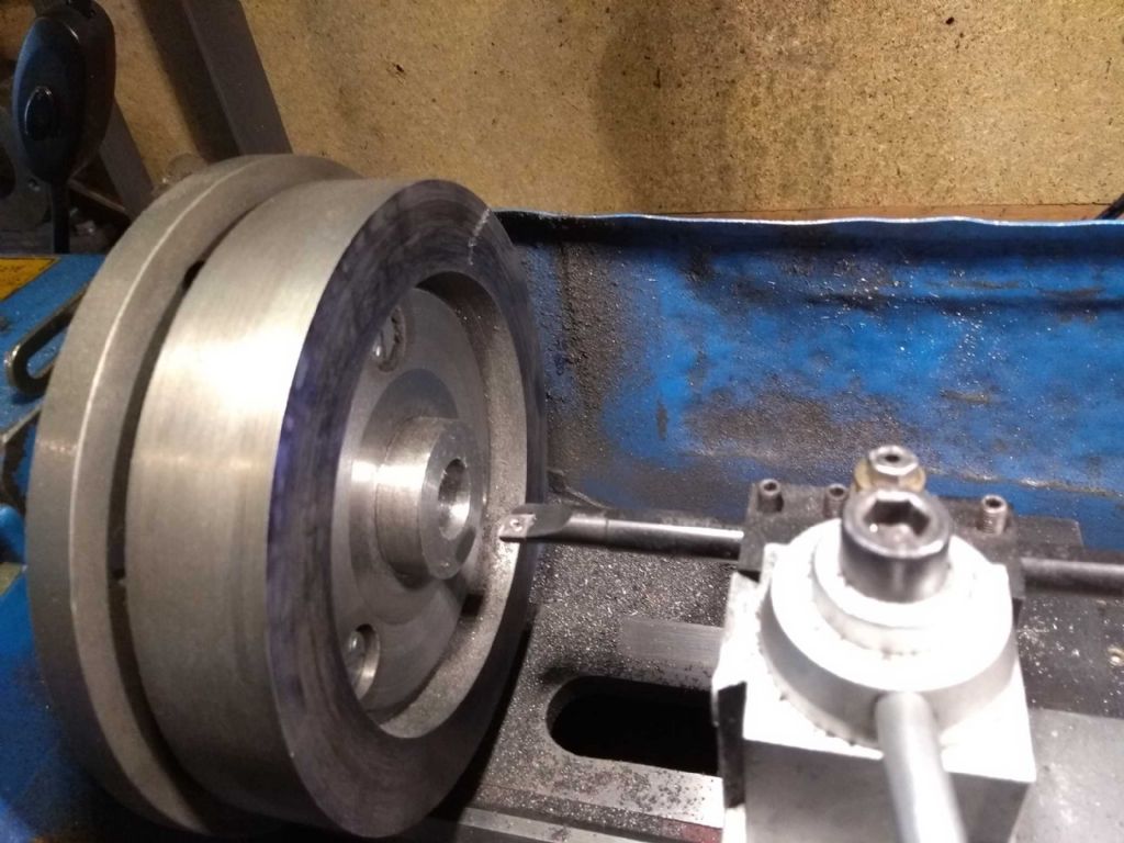
Needless to say, this isn't going to fit in a chuck (not on my kit anyway). After pondering for a bit, I decided that the thing to do was to screw it to my faceplate, face one side and hollow it out leaving a hub. I'd then hold the hub in a chuck face the other side and add a hub, then turn round and finish off.
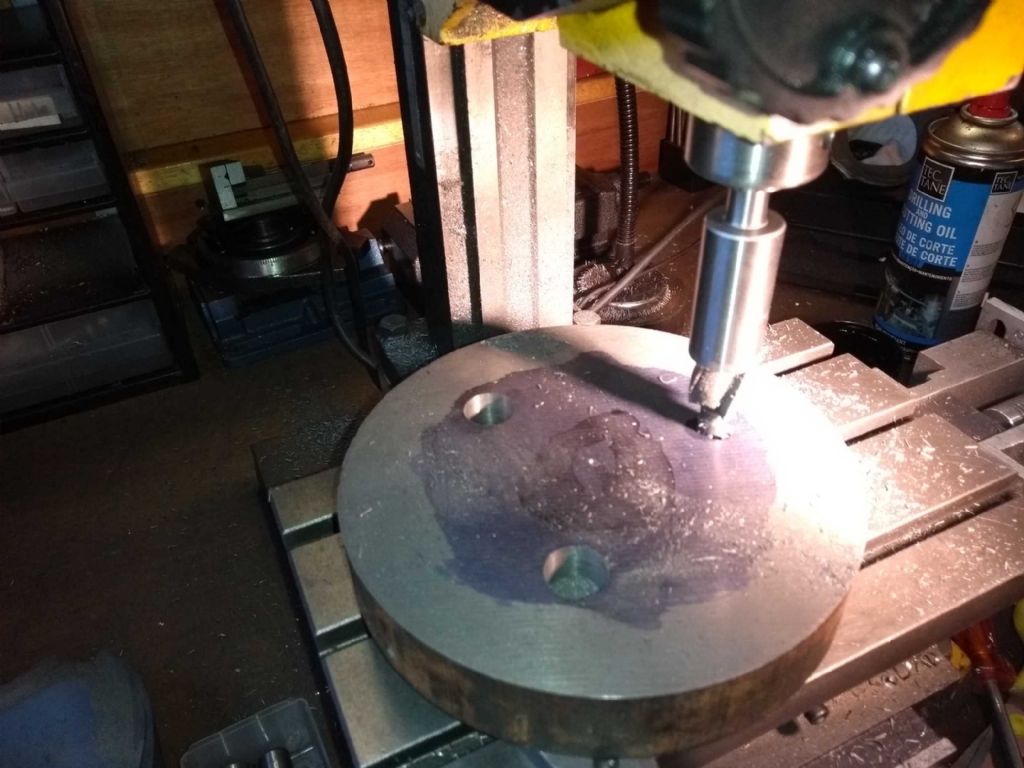
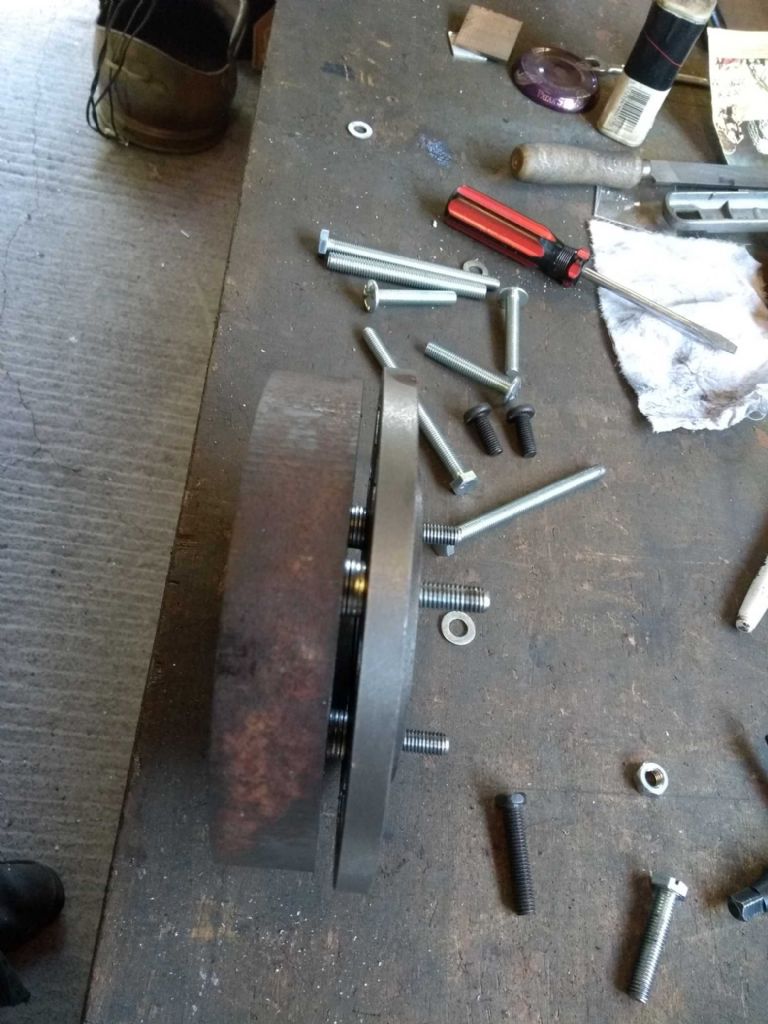
I marked the centre of the M6 threaded holes in the faceplate on the flywheel metal, drilled to 6mm (a bit more as I was a touch out) and counterbored to get some bolts in. The screwed it to the faceplate with some washers to stand off and mounted the faceplate on the lathe.
What I SHOULD have done (I think) is to glue it to a sacrificial plate of some kind and bolt that to the faceplate.
This way I had the issue of the interrupted cut on top of the hollowing (trepanning operation).
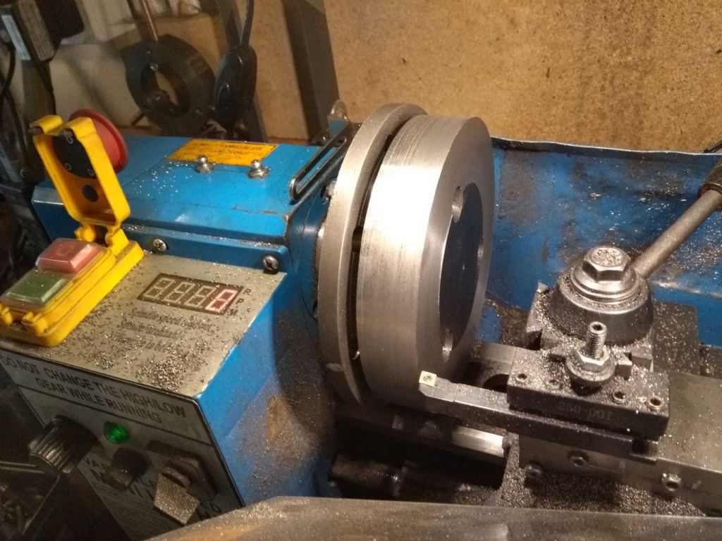
Anyway. I tidied up the edge with a indexed cutter.
One 'interesting' aspect of this sort of job is that the cross-slide has less movement than the radius of the work (even with a Wyatt modification), so you have to work on the outside and the inside of the toolpost. In this case I don't need a smooth face, so it's not actually an issue.
Then came the 'interesting' part. Digging into the face (trepanning) in order to get the middle out.
voracious readers of the forum will know that I had to seek advice on this from the beginners section. The resolution for me was to take the top rake of the trepanning tool, which reduced the chance of it digging in.
Nonetheless, this was a delicate and time-consuming operation. Having got a channel in which I widened with the tool, I could then get something more meaty in an carve out more of a hollow to leave me a hub to hang on to.
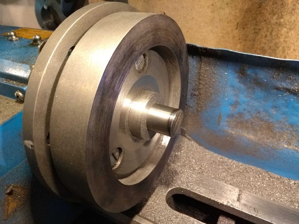
There! with some imagination you can see a flywheel starting to form.
And with the next step (boring the centre hole, first (image) with a carbide bar and then with a HSS tool for the final approach..
And I seem to have got this reasonably accurate. A silver steel offcut fits in rather nicely (same diameter as the crank)
However, i've changed my mind about holding it in a chuck. What I think I'm going to do is to make up a stub mandrel, face the what is currently the back part and then turn it round and finish off the hollowing out.
In fact, there's an argument for saying that I should have started off with the hole and done the rest on a mandrel. I'm not quite sure how I'd have made an accurate hole without the lathe. My mill isn't up to the job, I think.
Iain
15 July 2019 at 21:29 #419096Iain Downs
Participant@iaindowns78295Back to finish the job.
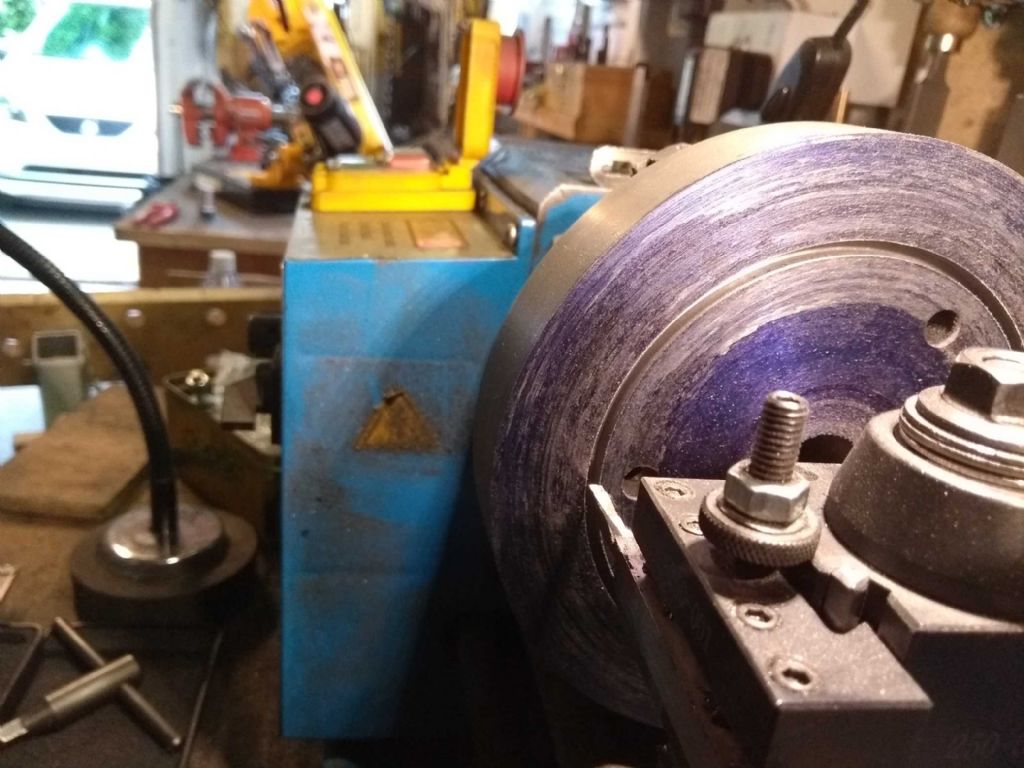
Having got the front side of the flywheel I set about carving out the back side. After some dithering and advice, I ended up by holding it on the inside of the flywheel shoulder with my 3 jaw.
This worked quite well though the piece was a bout 0.1 mm off-centre taking the outside of the rim as true. I had some thoughts on that – later.
Rather pleasingly, the trepanning on this side went really quite well. By now I'd ground the very hell out of the treppaning tool and obviously the million monkeys approach has finally worked. I think that a bit more relief on the sides of the tool helped.
Here we are a 5mm deep groove with a 3mm wide tool.
I took a few more cuts beside it – these being considerably easier than the groove itself – until the groove was side enough to get a 'normal' tool in.
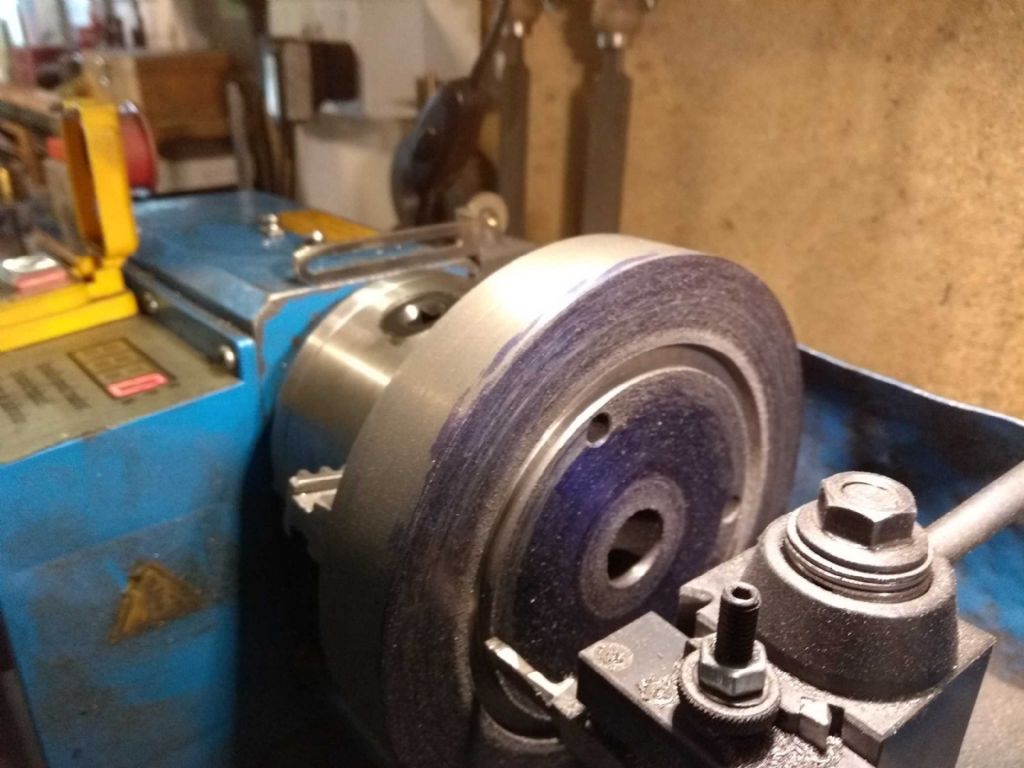
Once this was done, I turned the flywheel round to dig out the rest of the front side. This time, gripping the centre of the front side in the chuck, but bolting it through the spindle to give it a bit more strength.
This was gouged out with a combination of a pointed tool (hss on the right) to dig out the bulk and then carbide left and right knife tools to come up cleanly to the rim and centre hub (well, cleanly for me!).
I'd decided, though that 0.1mm of centre wasn't good enough and made a stub mandrel to mount it on and tidy up the back side.
I'd learned some tricks for this from Harold Hall, who said that you should put the topslide to a few tenths of a degree to put the taper on. When I came to measure this up, I found it was already about 0.6 degrees out (in the right direction)! I must go back and set it up correctly now I've finished!
And here is the flywheel on the mandrel being tidied up.
I still need to cut a keyway, to do which I need to make a broach, but that can wait until nearer the end of the process.
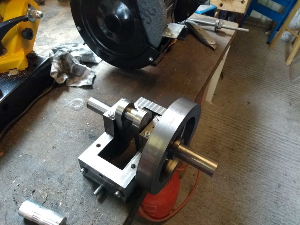
Here's the flywheel on the Crank.
Next I'll be assembling the con rod, cross head and so on. I've all the parts just need to turn the rods to the correct length and connect..
Iain
26 January 2020 at 09:12 #448952Iain Downs
Participant@iaindowns78295I can't believe it's 6 months since I posted on this thread. It's quite astonishing how distractions can take you away from building things – and perhaps no surprise that most of us (except Jason) seem to take months, years or decades to complete stuff!
In my case I became concerned about the accuracy of the lathe, discovering that the spindle had some lateral movement. This involved taking the headstock apart and attempting to thin down the spindle to be a smoother fit. Making some mistakes (never!) meant having to do some quite Heath Robinson kludges, but the result is good (in fact I've just retightened the spindle today and it's taken away a squeek).
Next I struggled a bit with some threading on the lathe – I never quite got to the end of that as I was distracted (further) by the search for a new milling machine. Should anyone find this journey other than stultifyingly boring, it's mainly chronicled in this forum…
But back to the real work!
So this week I've been finishing off the drive train. This is probably the wrong term, but i mean the bits from the piston down to the flywheel.
First off was to trim the piston down lengthwise to be exactly the right length, it being about 0.15 mm too long.
I have become a fan of wax chucks recently – with superglue playing the part of the wax. IN this case I had about 5 goes at making a stub mandrel and always seemed to end up a few thou too thin. I got bored and slathered some superglue on, with a nice bake at 250 degrees for one hour to free it.
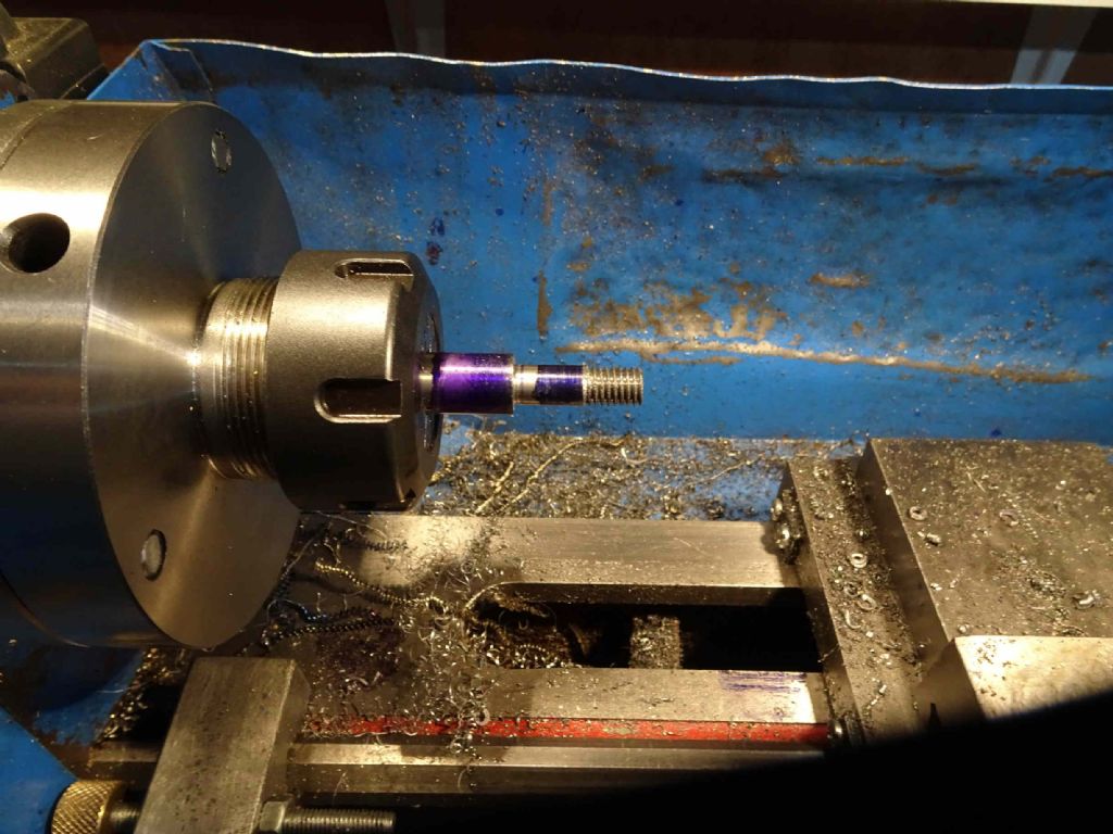
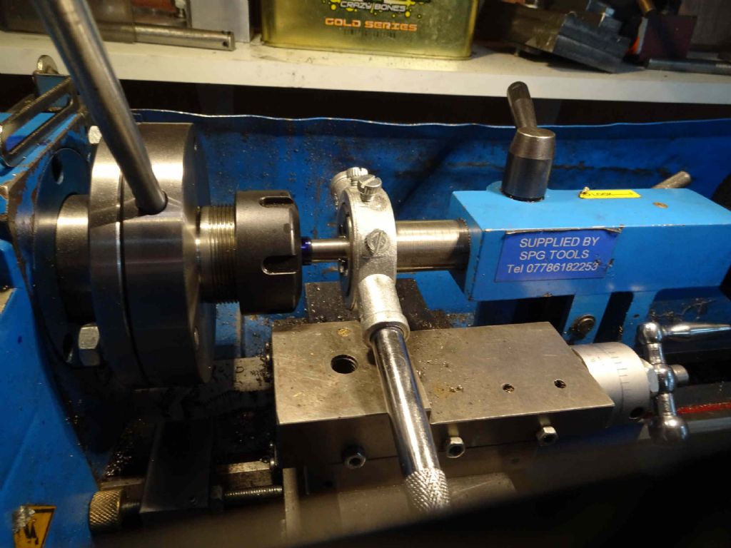
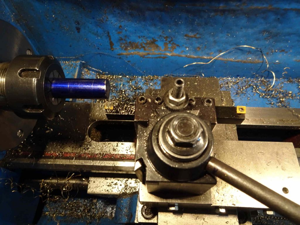
I finally got my ER32 stuff working. In this case using a collet chuck which attaches to the face of the spindle not into the taper.
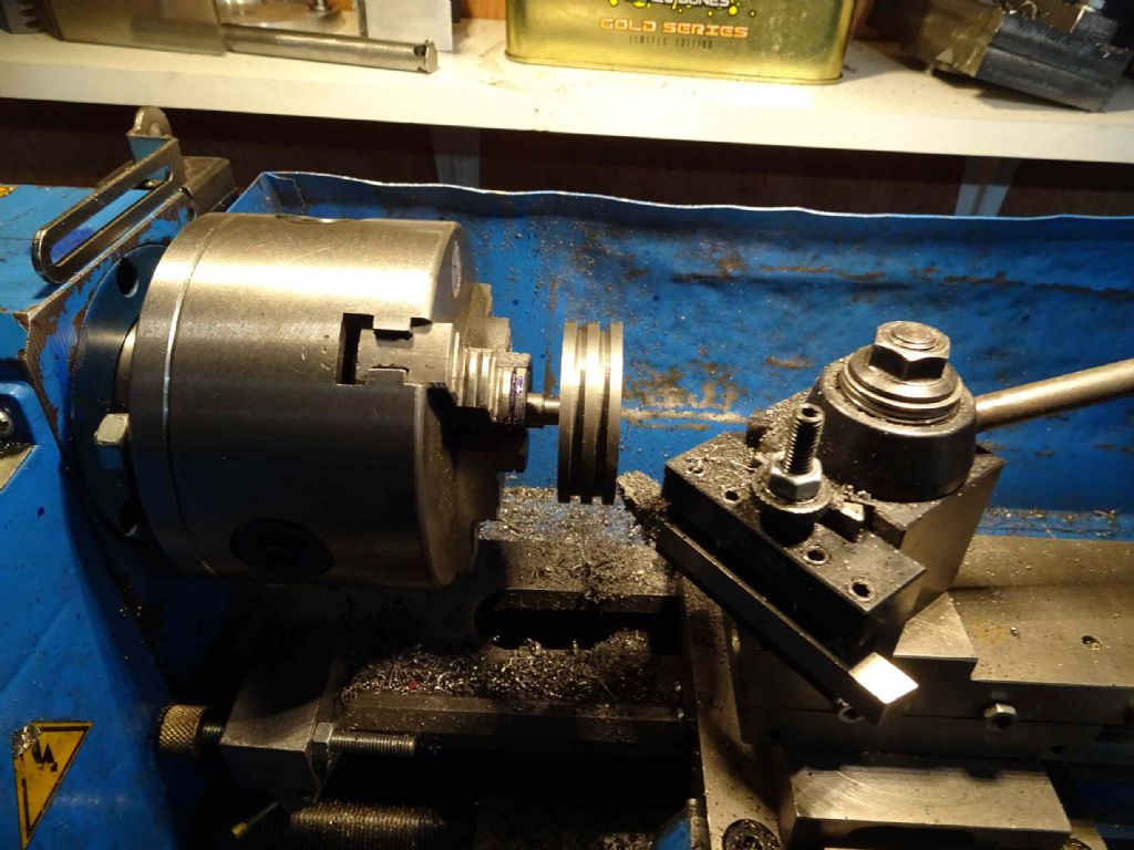
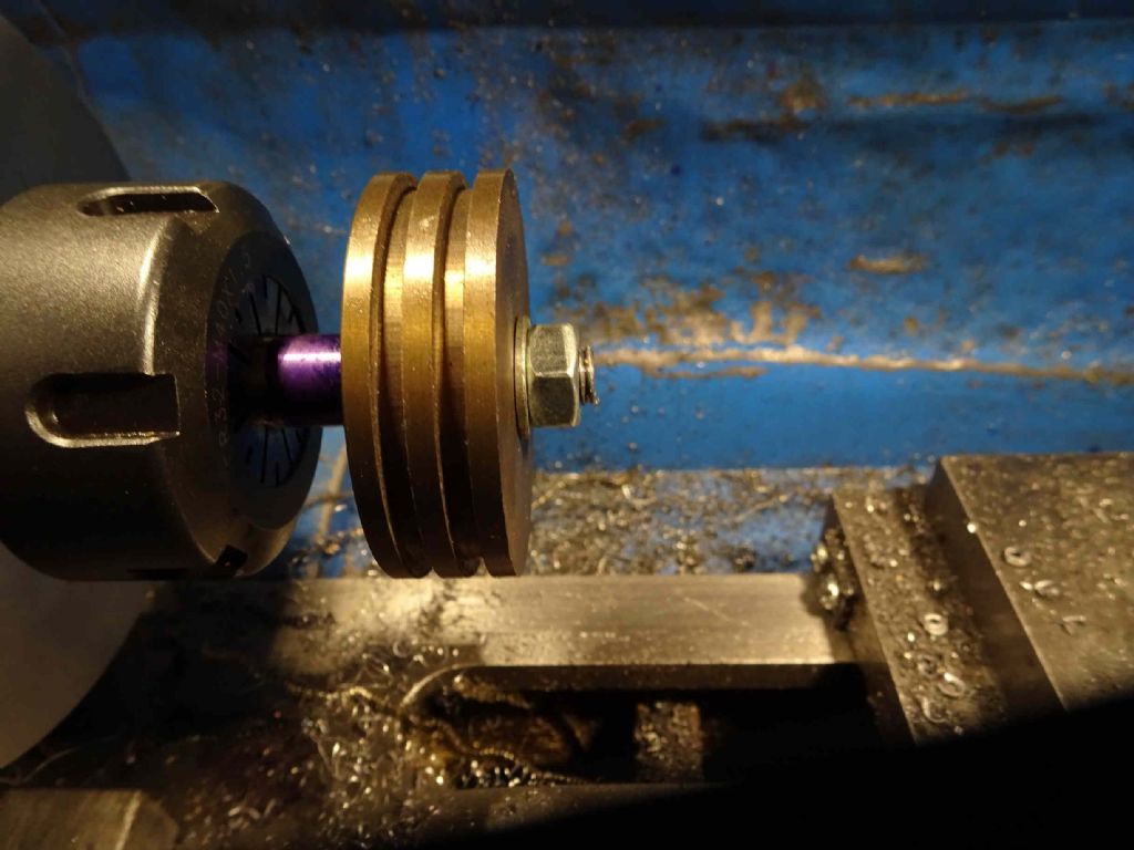
Here the 12mm silver steel rod is turned down to 8mm and then threaded. And, rather nicely, the piston fits on it!
Later I will clack it together with some threadlock and turn the piston down to exactly the cylinder width – but first I want to make sure all the parts fit.
The other end is reduced to 10mm and threaded 10mm x 1mm
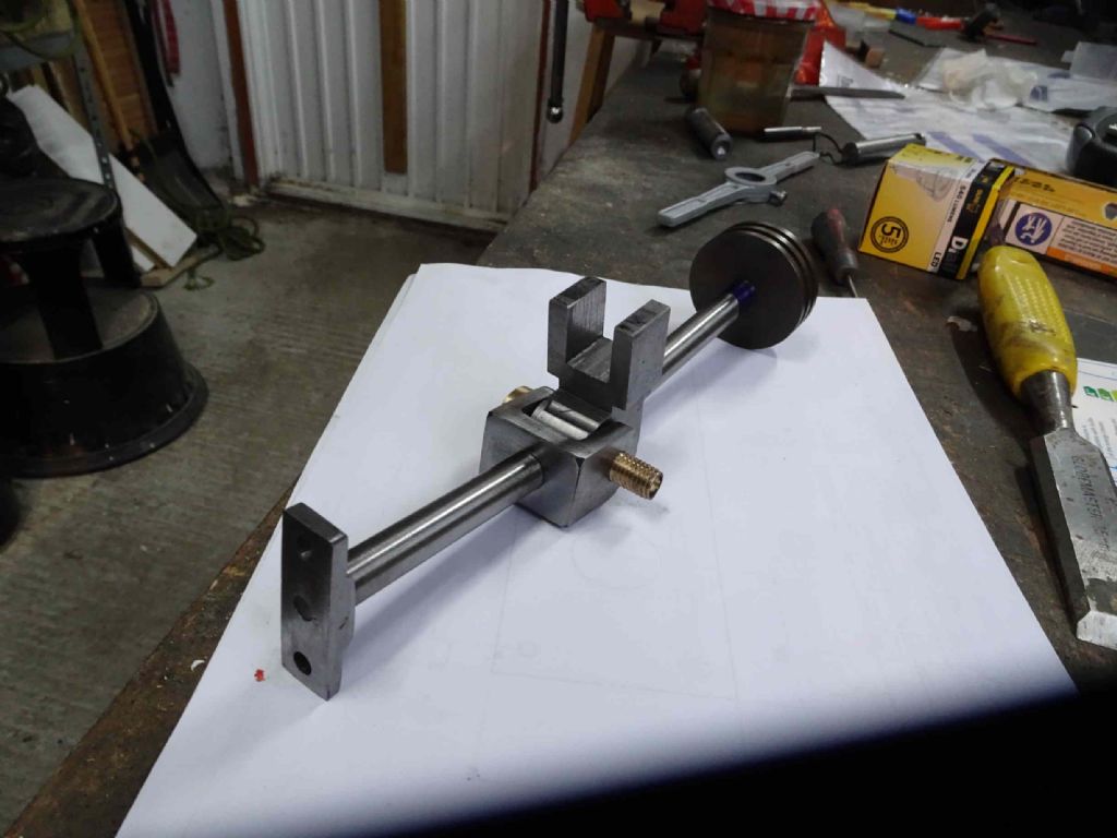
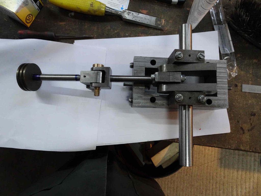
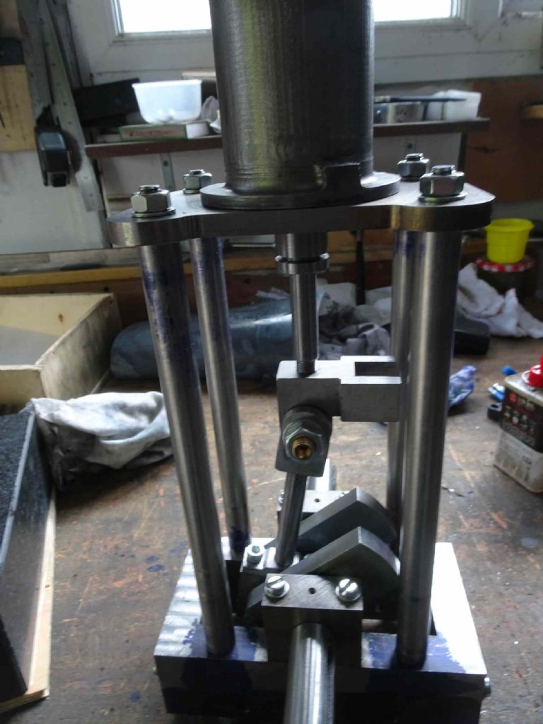
This fits into the crosshead to allow some tuning of the location of the piston and here is the whole connecting assembly put together.
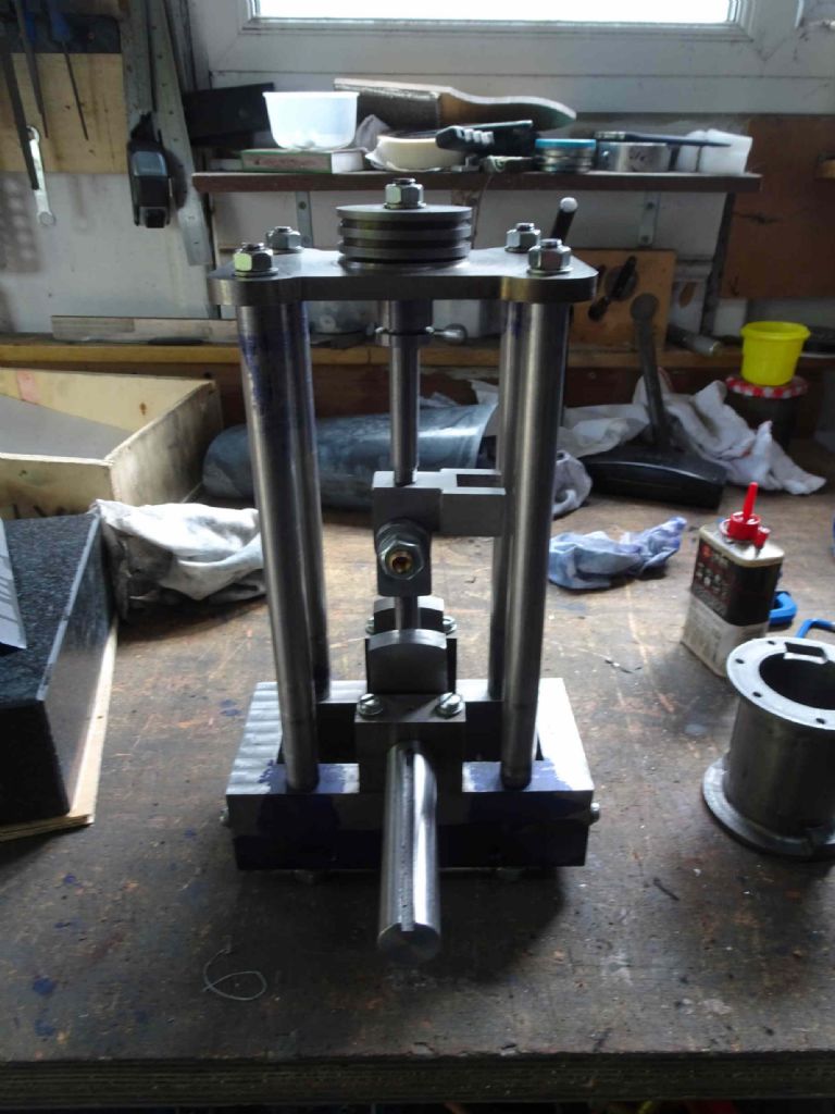
And even more remarkable, the whole powertrain (as I'm calling it)!
Next step is to make the lower cylinder plate and the supporting pillars. I'm hoping to start on that today, all being well.
Iain
2 February 2020 at 17:49 #450421Iain Downs
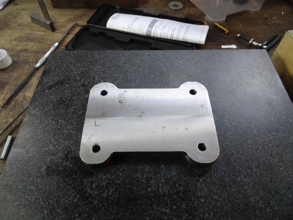
Participant@iaindowns78295The latest addition to the Steam Engine parts is the bottom cylinder plate. This supports the cylinder, holds the piston gland and will be supported by 4 columns from the base.
Starting off with a piece of 100 x 130 x12 EN1A.
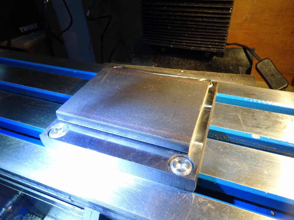
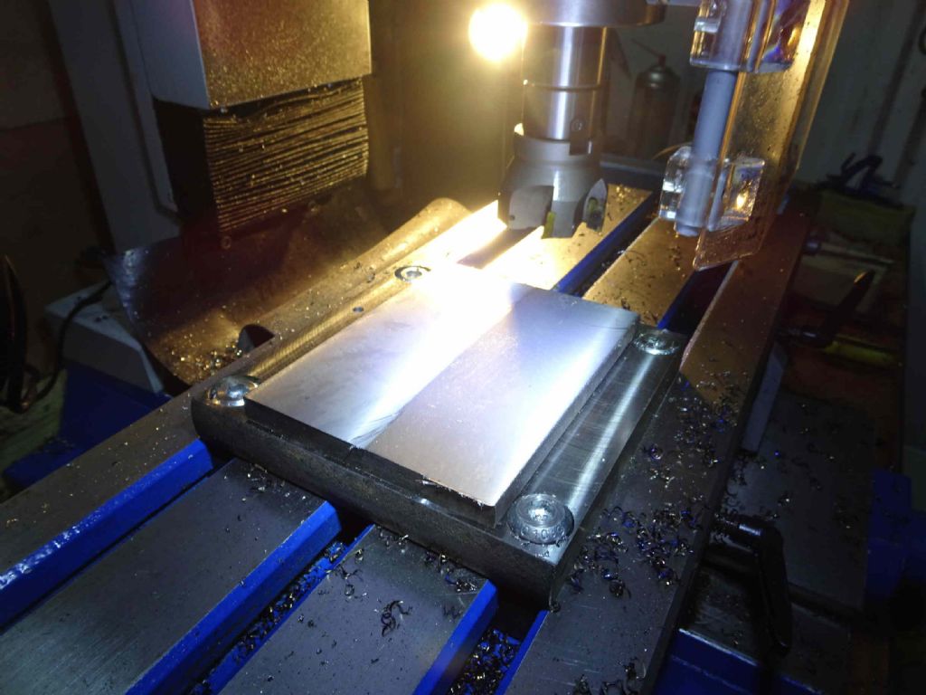
This superglued to my base plate and then skimmed – as well as wanting to get it flat, the plate is also 12mm and needs to be 10mm – Metals4U had no 10mm in stock.
Next, to mark the position of the holes required for the pillars using a transfer punch
And then complete the marking out – the bearing block isn't exactly central so I bodged what will be the centre of the cylinder a fraction to the right.
Next to mill recesses at the top and bottom, drill 8mm for the support columns and a centre drill in the middle which will be used to locate the piece on a wax chuck to turn down the outside leaving a spigot for the cylinder to locate.
ACtually, the drilling didn't work so well. I was trying to line up the centre drill with the punched dot by eye and I'm not convinced I managed it at all well.There was quite a bit of vibration at the start of all the holes, though I'm also wondering how accurate the chuck that came with the mill is. Something to investigate another time.
Now to try and make it look a bit less rough. To round the corners off at (I think ) 15mm radius.
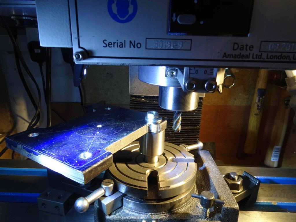
How to hold the plate on the rotary table? After some thought I found a MT2 stub which I'd used earlier that I'd tapped 10mm in the centre. Actually, I suspect it was only mainly in the centre, which led to the corners not quite coming out as I expected – or the holes are more off from the punched dots than I thought.
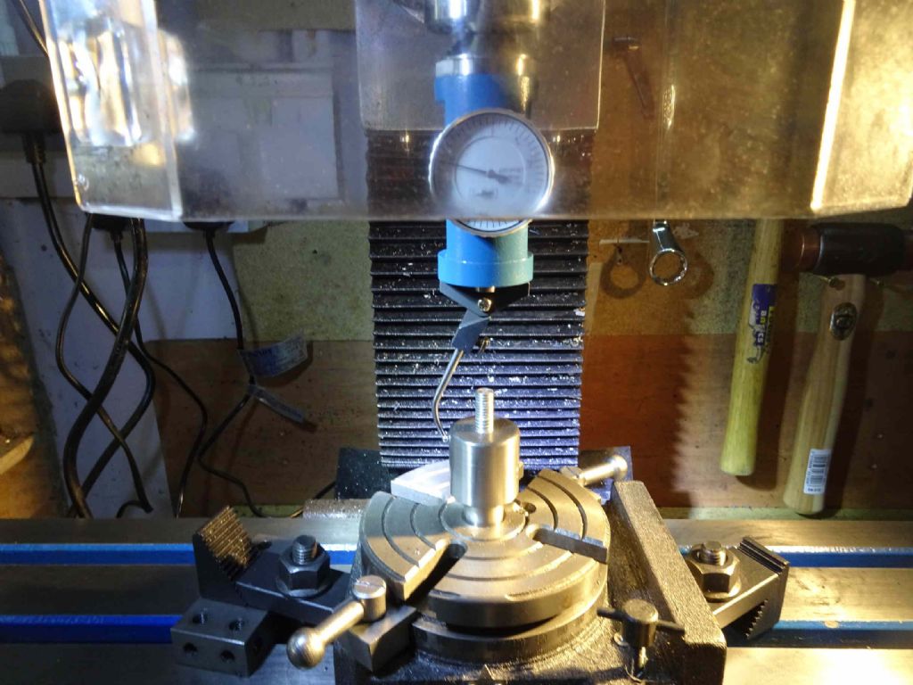
What marvelous things co-axial indicators are! You can see the MT2 'blank end arbor' fixed into the table with an M10 bolt and being centred nicely.
Then attach the plate at one corner and turn!
This worked surprisingly well, though I had to have two goes at it. The first time I'd not tightened the drawbar bolt enough and the MT2 slipped.
Oh you may notice that the guard has gone. Simply put it stopped the piece moving sensibly. It was encouraging to know that I can take the guard off just by slipping it out and the microswitch defaults to 'closed'. Obviously Weiss expect this! Not sure if I'll bother putting it on, though I will re-evaluate next timing I'm facing with the 63mm face mill which chucks hot swarf EVERYWHERE!
This is the final result of the milling
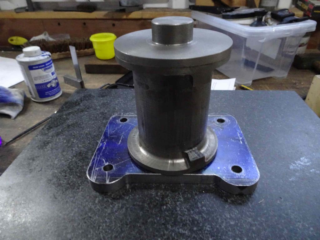
And with the cylinder more or less as it will be
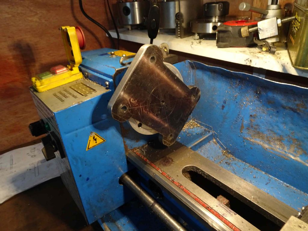
The next task for this piece is to mount it on the lathe and skim off all bar the centre spigot to locate the culinder. Also to bore the hole for the piston gland. Thinking about it, though I think I need to make the piston gland first so that I can try fit it. the way I'm thinking I need to make the gland may not be as accurate as I would like – so that first, then complete the plate.
It's starting to feeling like at least the end of the beginning!
Iain
6 April 2020 at 19:14 #462826Iain Downs
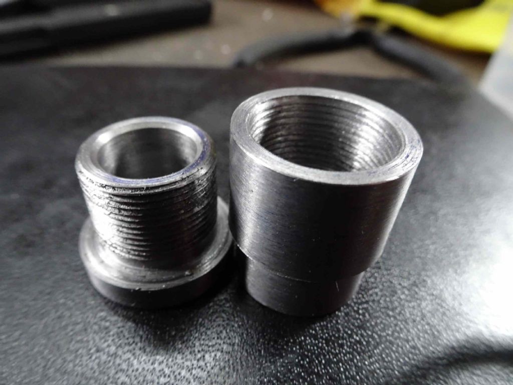
Participant@iaindowns78295Apologies for a fair chunk of no results for a while. The piston gland demanded I do something about internal threading on the lathe, which, frankly I found challenging. There's more of my moaning here .
However, in the end I've got a reasonable result.
I've also been attempting to design some Stevenson reversing gear (tangent mates in OnShape are not entirely intuitive) and hope I can post something soon for experts to argue about!
Bottom plate is next and when that's done I should be in a position to make the support pillars and do a trial assembly. Perhaps the Easter weekend will be kind to me (if I can avoid painting the fence).
Iain
6 April 2020 at 21:24 #462852Paul Kemp
Participant@paulkemp46892Iain,
Loving this thread and your approach. Keep it up, really interested to see the final result.
Paul.
13 April 2020 at 17:53 #464438Iain Downs
Participant@iaindowns78295A good weekend. First time in ages I could be in the shed with no heating and the door open. More of that to come I hope!
The main thrust this weekend has been to complete the bottom plate of the engine. The cylinder sits on it and is supported by some struts above the crankcase.
I started on this some posts (and months) back, but didn't want to do the lathe work until I had a piston gland to try fit as the other way round just wouldn't work.
I've become fond of the superglue chuck, though I still have some issues with release and heat. I have some blue masking tape, but haven't used it yet.
I seem to struggle with interrupted cuts – which this clearly is. I suspect I would be better off using HSS tools as the carbide tools used here seemed to chip easily.
I also had a nasty few moments with fairly horrid grinding noises coming from the lathe and the spindle showing hesitations. I was terribly afraid that I'd broken the change gears which, frankly would be a nightmare, despite now having specialist tools to remove and replace.
It turned out that the motor had worked loose and the timing belt was loose and slipping raggedly. Not fun, but much much easier than a gear replacement!
Still it worked in the end and the results were pleasing
And this with the piston gland in position. I've not decided if I want to attempt to solder this or to glue. Soldering feels nicer, but it's a big chunk of steel.
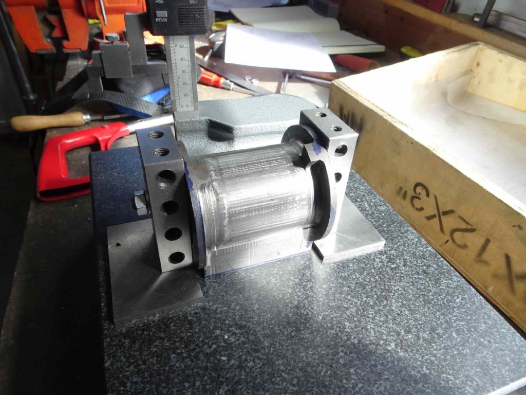
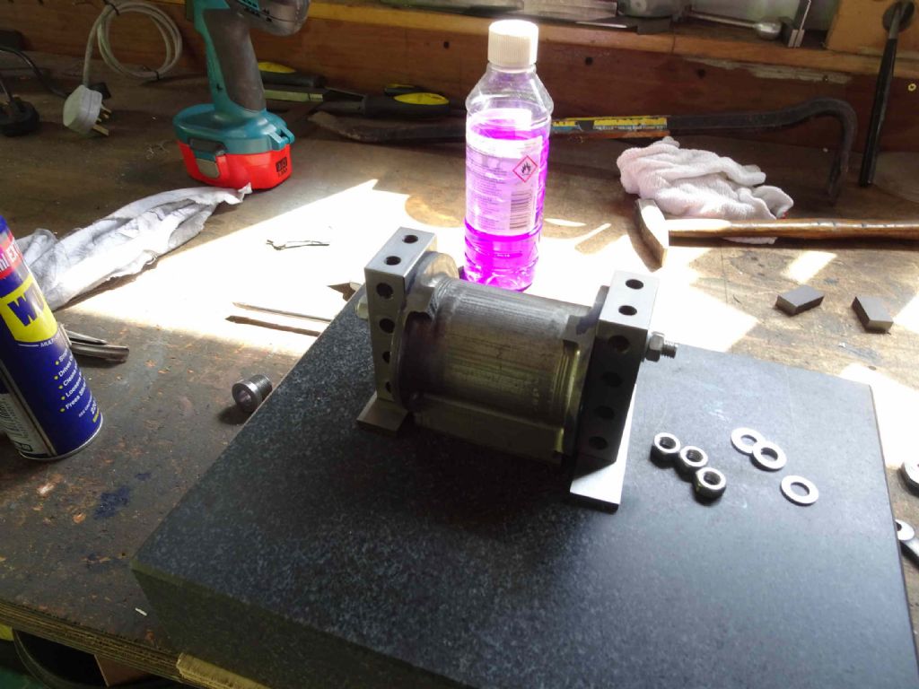
Next is either the pillars to support this or cutting the valve ports. I've started to set the cylinder up for this. Here I've bolted the cylinder to some 2 4 8 blocks with the port face flat against the surface plate/
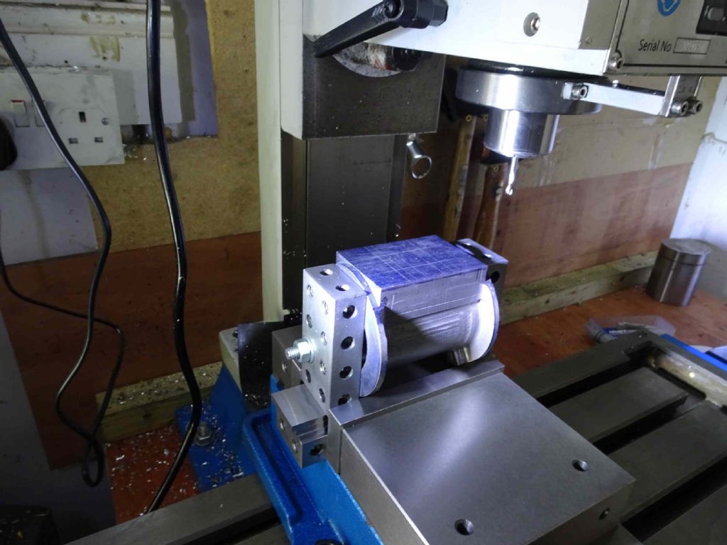
Turn it round and clamp it to the mill and ready for go.
Unfortunately my DRO kit for the mill hasn't turned up yet so it's going to be a question of taking a great deal of care. I'm expecting the markings to be for checking and the mill for accuracy. I'm also trying to work out if I should use a 5mm bit for the 5mm slots or a smaller one and multiple cuts. The mill seems to be pretty accurate when cutting a slot. Hmm. Why don't I find some 'scrap' cast and experiment!
Iain
18 April 2020 at 16:11 #465483Iain Downs
Participant@iaindowns78295I've put the port machining on one side for the moment as I wanted to get the support pillars done – at which point I would have a half built engine rather than a box of bits.
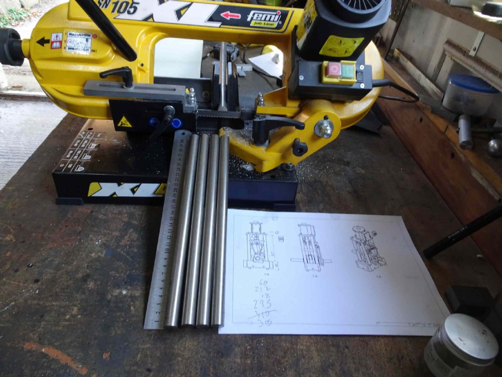
I started off by cutting some stainless steel (16mm) to a bit over size on my rather lovely Femi bandsaw (there's a table for the bandsaw in the works and I'll report on that when done).
In fact with my propensity for cutting a bit to firmly, I cut beyond the strict length (295mm) by 10mm. In the end I had to trim 9.8 mm off so next time I will be less careful!
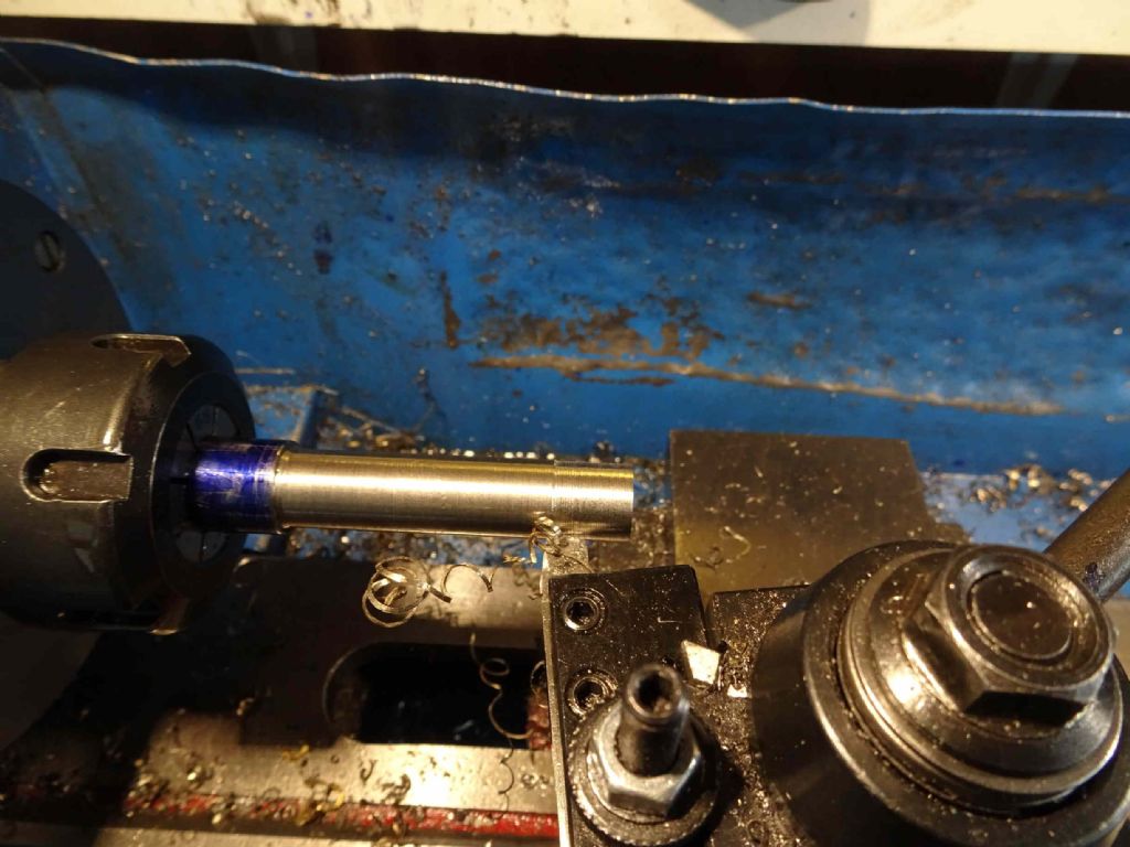
The next task was to tace one end and then turn down to an exact length. The idea was to get the overall length spot on and then reduce the shoulder to exactly the right length. This didn't quite work out so I had to make final check after removing and measuring the bar length
As you can see I'm using a collet to hold the bar. I still seem to get a little wobble, but decided that it's not important for these bars. I'm hoping that when I come to finish the cylinder the ARC 12mm collet will not give me any problems!
First take the base end down to 10mm for 60mm, then the top down to 8mm for 18mm.
What was confusing about this was the behaviour of the different tools I used.
I started off with a indexable carbide tool onto which I put my last tip. CCMT060204 from a box of 10 from ebay.
These did not work at all well, It was like the bar was made from pure Aluminium – soft and sticky. I abandoned the carbide attempt and turned to good old fashioned hand ground HSS
The tool for bulk removal is quite chunk with a angle of about 100 degrees. This worked quite well, but the long long swarf was coming off straw coloured and bloody hot I can tell you! Even the bar itself was turning a yellowish colour. Speed was about 700 rpm.
Once I was within a couple of mm of the correct length, I switched to a very pointy hss tool to skim off the last mm or so.
This worked OK (though it took a couple of sessions) and I got through all the 10mm ends and then called it a day.
I was delighted to find that some new tooling I'd ordered had arrived
This little chappie also came from ebay and has the interesting double ends. I've also ordered some tips from ARC, with the idea of having some tools for roughing (0.8mm tips), finishing (0.4mm) and aluminium (different wierdo numbers)
Anyway, It would seem wrong not to try it out! My goodness, what a difference! This tool cuts beautifully! I can take 1mm cuts (though that was straining the lathe a bit so I ended up taking 0.5 – 0.75 cutts( and the finish is excellent.
I believe that quality of carbide tools has been discussed on the forum recently, but this was a real eye-opener.
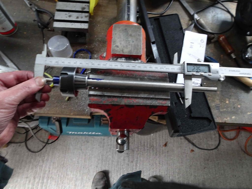
As I mentioned above, the attempt to get the right inside (leg length) dimension by measuring down from the ends didn't work particularly well with nearly 0.5mm variation between the 4 legs. So I popped them back in the collet and took a bit more of each and ended up well within 0.1mm – 4 thou. For god's sake, they're only legs!
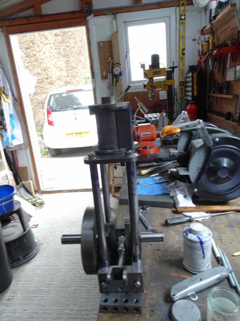
And here it is. With a little imagination you could believe that one day it will grow up and become a steam engine!
Iain
18 April 2020 at 16:13 #465485Iain Downs
Participant@iaindowns78295IN passing, the 300mm calipers were on my Xmas list for 2018, requested, specifically for measuring the legs. It's an indication of how long these hobby projects can take that I've only just used them, 16 months later.
Hopefully, I will find something else long to measure in the not-to-distant future.
Iain
8 May 2020 at 16:31 #470143Iain Downs
Participant@iaindowns78295A little more done today after various distractions. I've honed the cylinder with a cylinder hone. Which took a few minutes. It took a good deal longer to find the cylinder hone as I'd put it away 'somewhere sensible'.
Also trimmed the piston on the piston rod down to be a close fit in the cylinder. There was a slightly lumpy bit at one end, which the cylinder hone also took care of.
Finally, I took a little bit off the inside of the piston gland so that the cap would screw down a little more. about 20 seconds work, but a good 10 minutes of random walk trying to get a good register on the 4 jaw chuck. Still that's an improvement!
Next steps would seem to be soldering the piston gland to the bottom cylinder plate and millling the valve ports.
I'm not sure whether to break and heat treat the piston rings at this point or if I should leave them intact until final assembly. I will probably leave them for now. I'm still a long way from having it ready to run.
Iain
10 May 2020 at 17:41 #470686Iain Downs
Participant@iaindowns78295Valve ports yesterday. Though clearly a little bit too much of happiness juice as I appear to have uploaded the pictures twice. Or it's just old age…
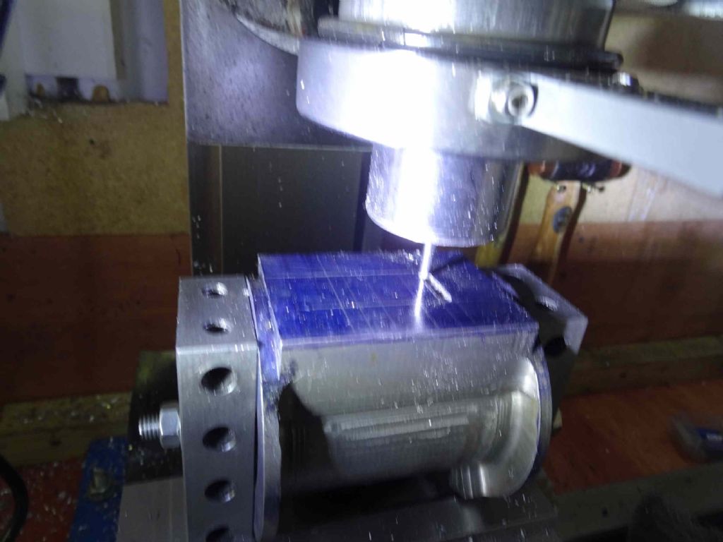
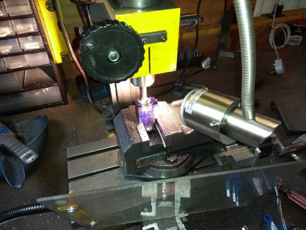
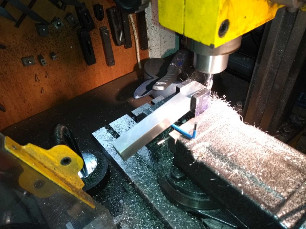
On the whole this went well, though I was attempting to do the cutting by eye against marks made with a scriber. The marks were fine, but I hadn't take into account the difficulty of seeing the work piece with a great big spindle in the way and a whole bunch of cast iron grit. Made me wish my DRO had arrived.
Here is the piece being setup to be accurately held in the vice. Turn it upside down on the surface plate can clamp some 20 40 80 blocks to it, then sit it on those.
This then gets gripped in my new big vice – though I'm realising that I how need to get some bigger parallels. It never stops, does it?
I was quite worried about milling 11 mm deep slots in the face and even more worried about the 25 mm deep slots at the end, but I had no dramas at all, cutting about 1.5mm deep each time. The DRO on the spindle is a joy. At one point Madam returned from some shopping exhibition (tip – queue too long and waitrose queue too long) and had to tell me about it. With my old mill I would have no idea how deep I'd gone and need to start again.
When I said, no dramas, That was true of the actual deep cuts, but when milling the end of the face there were some odd noises and a ping as the cutter gave way. I have no idea what I did. the replacement cutter finished it off fine.
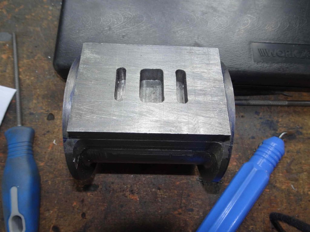
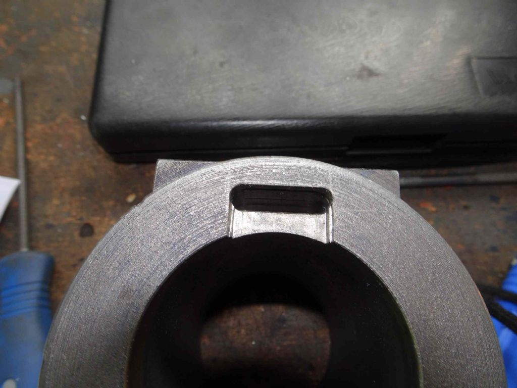
And here are the results.
In truth they could have come out cleaner, but I'm mainly content that I haven't ruined the cylinder. It would have made me deeply sad to have to start this again!
Next step is probably to drill and bold the end caps in place or possibly a trial fit even without out that. If it turns out that the throw is longer than the cylinder…. Well, I;ll probably make a clock.
Iain
11 May 2020 at 16:55 #470940Iain Downs
Participant@iaindowns78295I find myself a bit of a fair-weather modeller. If it's sunny outside, it's nice to be in the shed. If it's grey, cold and drizzly, then the armchair has some attractions.
Today was spent doing a bit more work on the design for the engine. I know, a bit late to be messing with it now…
However, I decided that I might as well add some valve gear as it won't add a huge amount to the time I've already spent – and better now than trying to add it later.
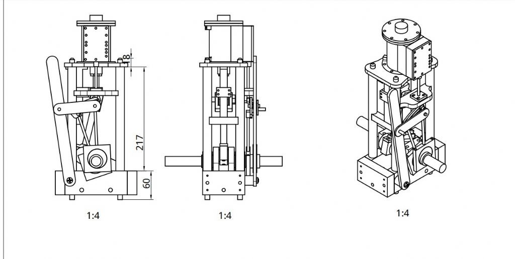
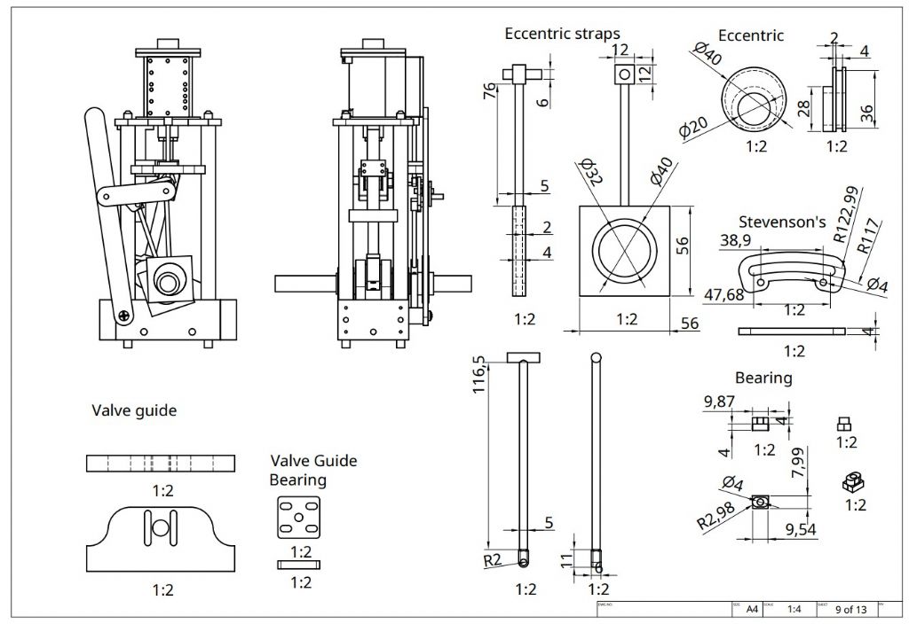
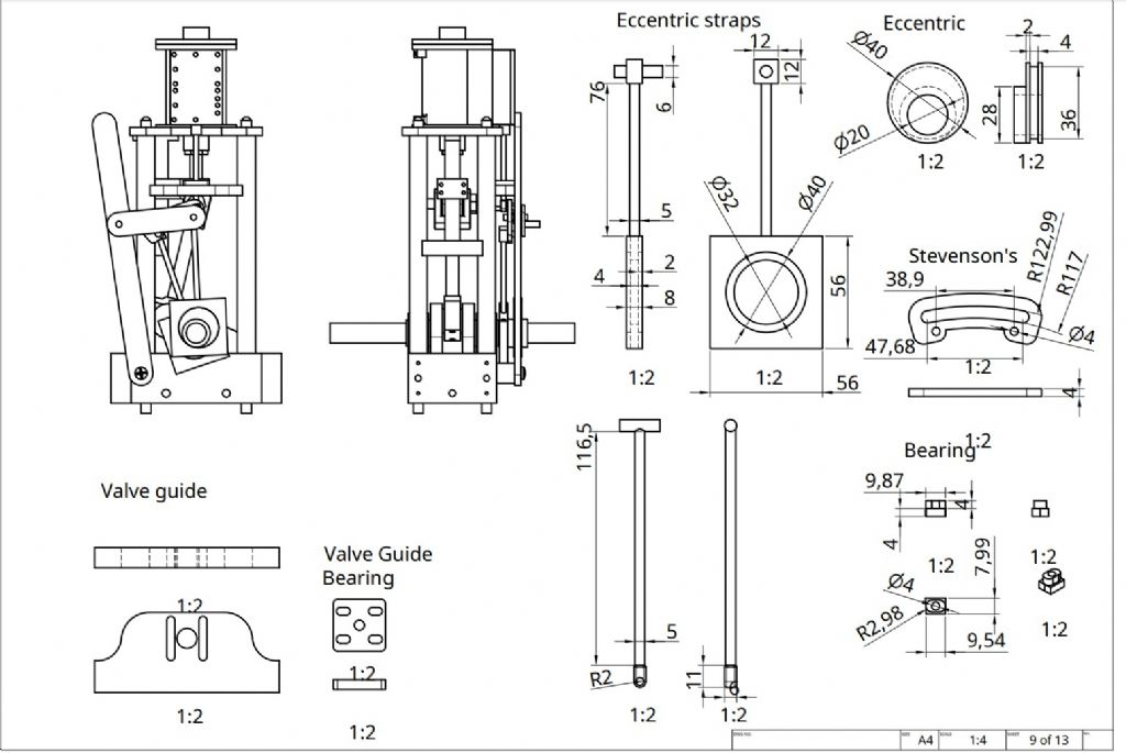
Here are some drawings. The first giving an overall impression of the engine and the second for the valve gear.
I might make some cosmetic changes such as rounding the eccentric straps. Also the straps will be split and bolted together and the eccentrics have grubscrews to fix then to the crank.
My main concern is about sizes. I see in some engines that the eccentric rods are fat things, whereas I didn't see the point. Mine are 5mm, but perhaps that's too small, particularly in EN1b – would silver steel be better. By the same token the eccentrics are quite thin, but equally they don't have a huge load.
I'm also not sure of the best material. I was thinking of cast iron for the eccentrics and mild steel for the straps.
Broadly, the two eccentrics are fixed to the crank with grubscrews. The eccentric straps are connected to the Stevensons link and the bearing connects to the top eccentric rod (bottom, middle, unlabelled) which passes through the valve guide bearing that is secured to the valve guide and thence passes into the valve chest. Please ignore the rod at the top of the top eccentric rod. That will end up a thread that ultimately connects to the D Valve.
OH and I will need to work out some way of locking the Stevenson's control lever. Probably something from the bottom cylinder plat, but not sure what exactly.
The other thing I wanted to check is the way I'm securing the cylinder to the top and bottom ends. I'm planning 7 M5 bolts at 50 degrees apart, except for a 60 degree gap where the valve ports are. top and bottom to be held by thread into the cast iron (5mm thick) of cylinder flange. Is that enough and will bolting directly into cast iron be strong enough.
On the practical front I've made some hold-downs for my rotary table so I can secure the cylinder to it.
Iain
11 May 2020 at 17:12 #470950 JasonBModerator@jasonb
5mm dia rods should be OK but your dimensioned 4mm straps sound a bit thin and are actually shown thicker than the 5mm rods, 6-8mm would be better.
Thread the top end of the valve rod and have a rectangular bar that screws onto it so you have some adjustment
5 x M5 should be OK.
13 May 2020 at 18:01 #471470Iain Downs
Participant@iaindowns7829514 May 2020 at 20:59 #471805Iain Downs
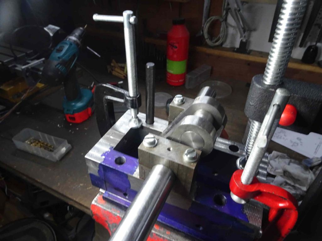
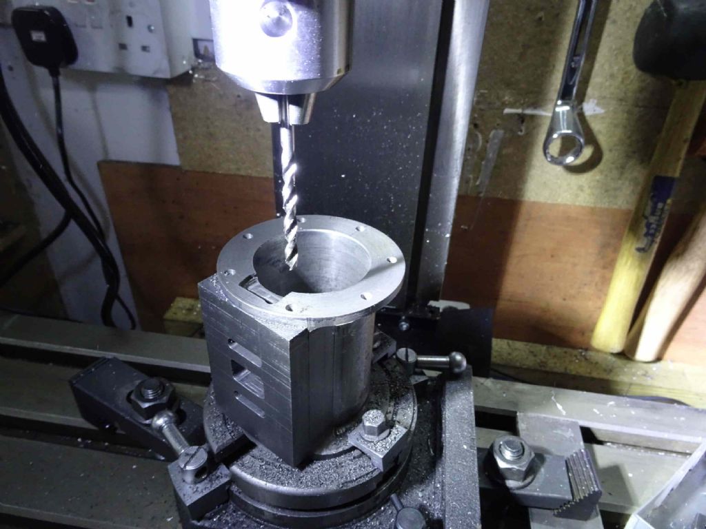
Participant@iaindowns78295Today was about starting the assembly process for the cylinder. What I needed to do was to drill 7 holes in just the right place in the cylinder cap and cylinder. Errors would be disastrous!
Here's how I went about it.
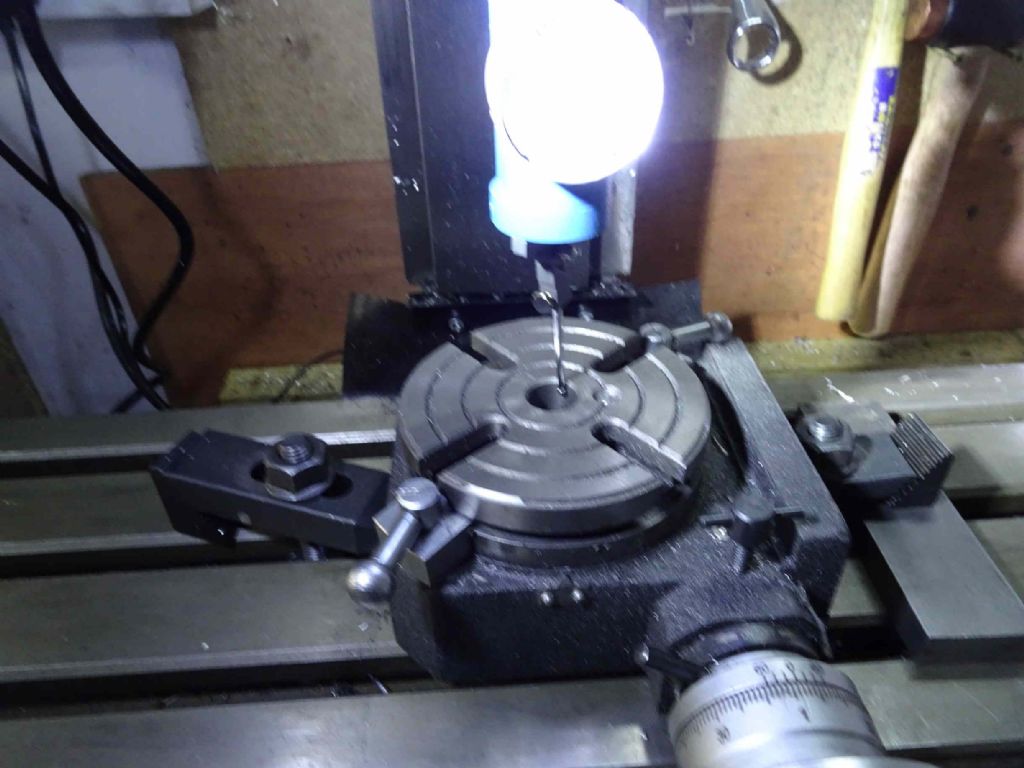
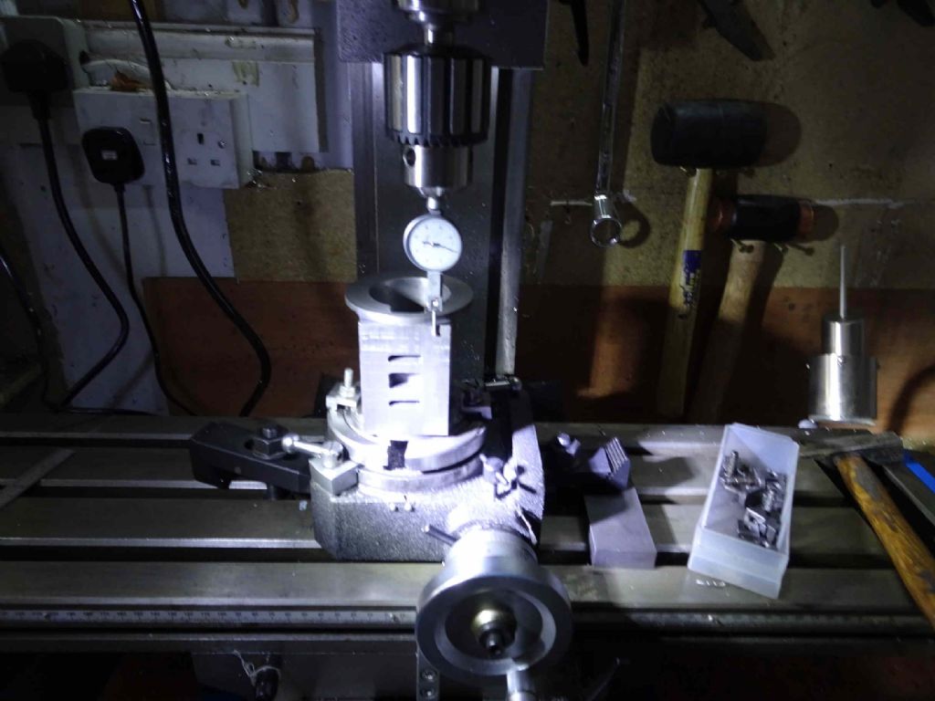
Firstly, I put a rotary table on the mill and centred it with a co-axial indicator.
The blurry bright thing is actually a co-axial indicator and I love it!
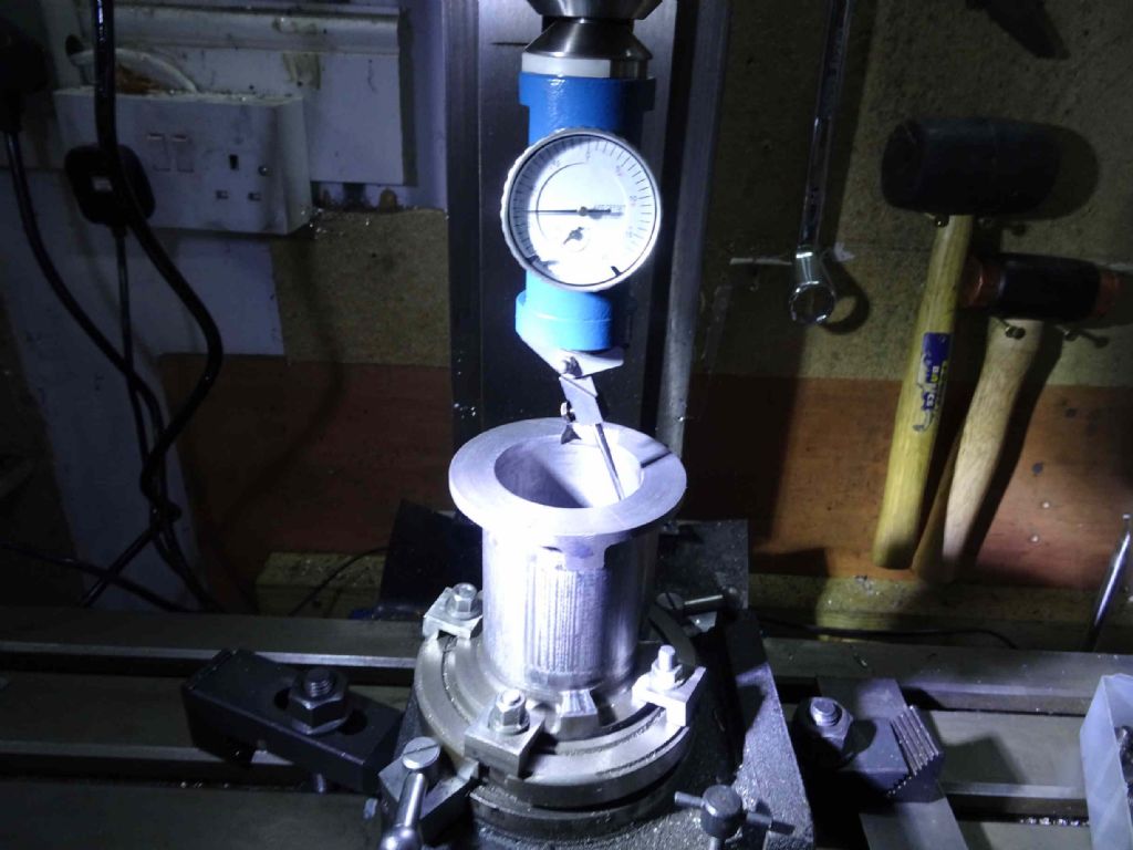
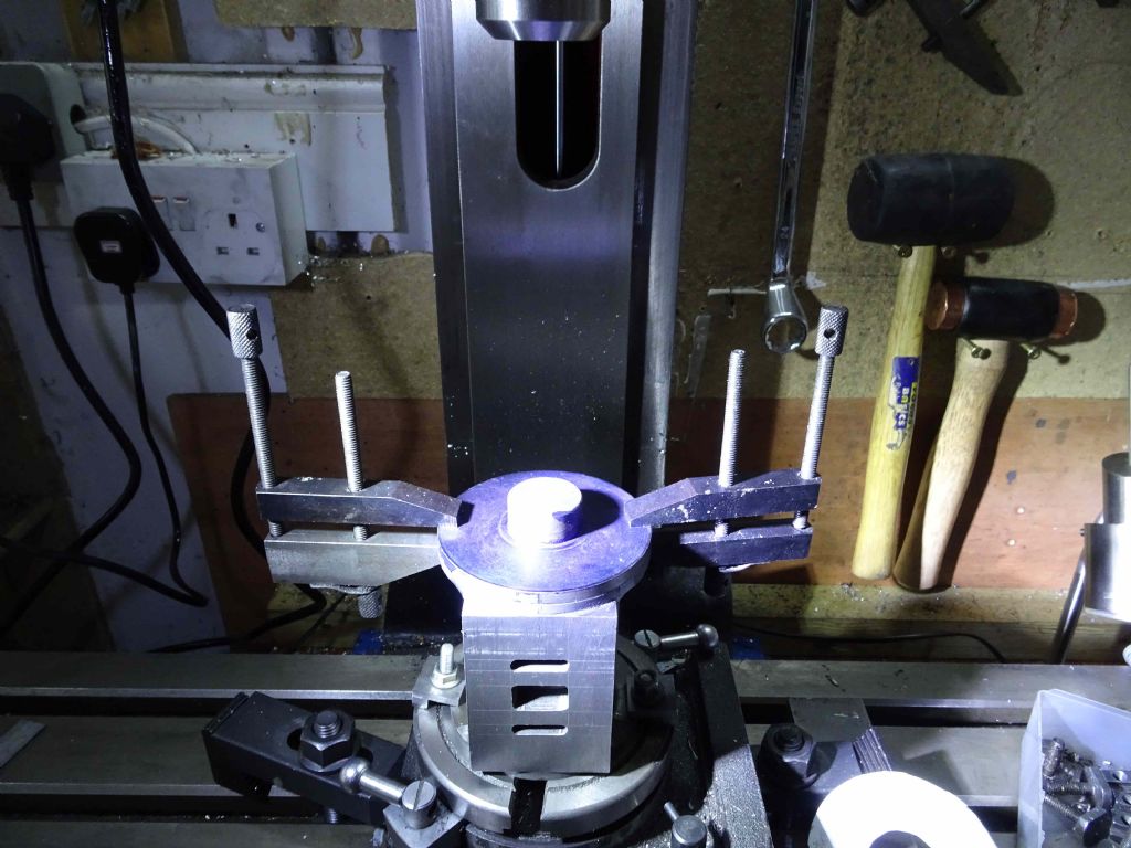
Next with rotary table centred, I mounted the cylinder clamped it to the rotary table and proceeded to centre that with the coaxial indicator and judicious taps from a hammer. This only just fitted (and I can see a bigger rotary table sometime in my future, but probably not soon) and I'd had to make new clamps to clamp it.
II was able to centre the table pretty much spot on (under 0.01mm), but I only managed about 0.05mm (2 thou) with the cylinder. I was pretty happy with that, actually.
The next step was to align the valve face along the mill axis so I had a registration point for the rotation. This meant unlocking the mill table and winding back, turning the rotary table so that the face was at the front and then clocking it, getting the face parallel to the mill by turning the rotary table.
The, back to the coaxial indicator to re-centre the cylinder, now I have the face parallel to the X axis and the whole shebang under the spindle.
Lock the X axis and wind forward 35 mm.
Oh and clamp the cap on lining up registration marks on the cap and cylinder and taking care to avoid where the holes will go using a printed template.
What I actually did next was to do a trial run. 7.5 turns, 12.5 turns (and another 6 like that) then 7.5 to bring me back to the registration mark at the front. At each point I marked the cap gently with the drill bit. Since I ended up where I started I thought my practice had gone well!
Also when actually drilling I could check my counts against the previous marks to make sure they were correct. They were (much to my relief).
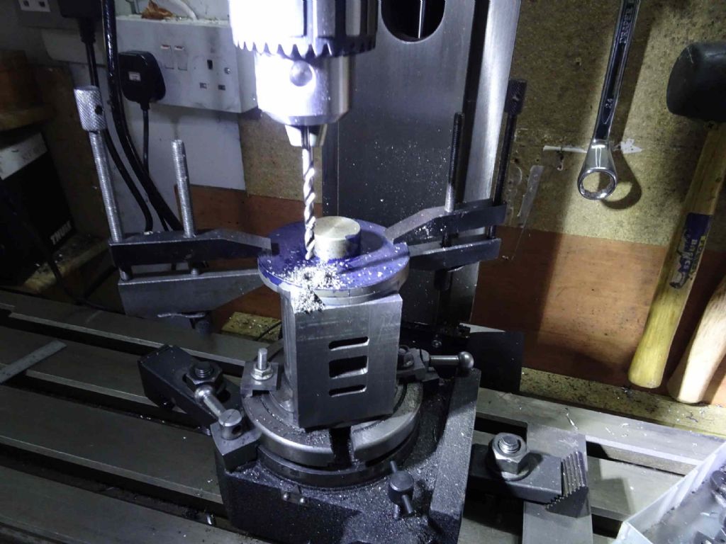
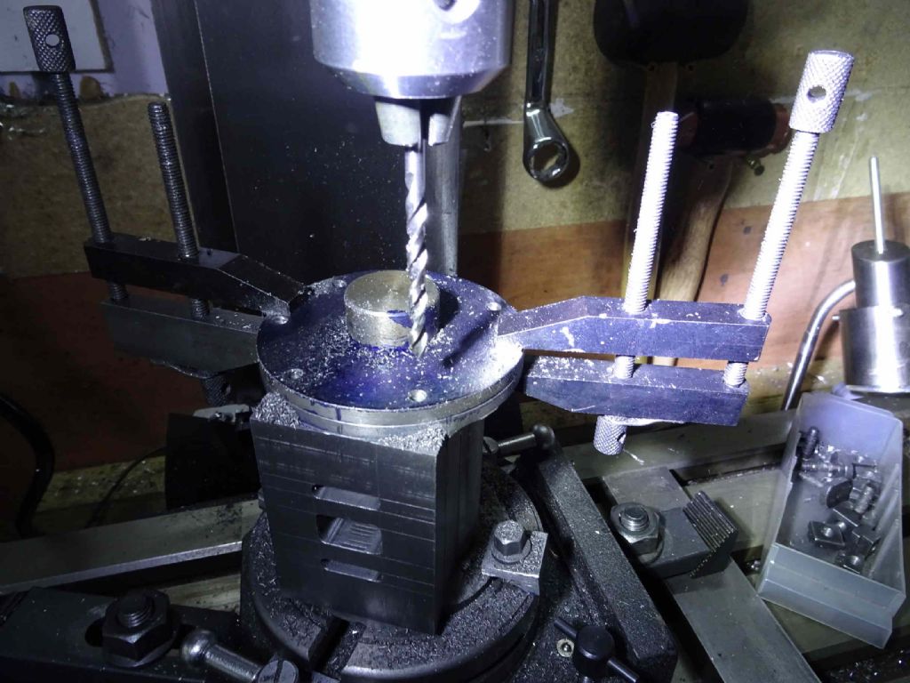
First hole drilled
Then the rest
And taking the cap off, all the holes in the cylinder are nicely inline.
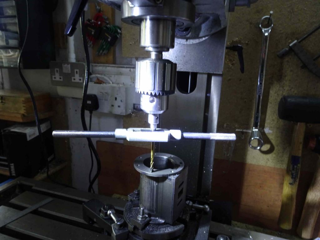
I'm trying to decide if I should use the same process to tap the holes (in this case not under power), or do them by hand off the mill. Provided I can line up and don't miss my counts it would probably be better to tap on the mill, so I think I'll do that.
Next is to do much the same with the bottom cylinder plate.
Iain
14 May 2020 at 22:24 #471825Chris Gunn
Participant@chrisgunn36534Ian, if the cylinder is still set up, I would put a centre in your drill chuck and use this to locate the tap wrench to hold the tap straight, and then tap by hand.
Chris Gunn
15 May 2020 at 08:05 #471856Iain Downs
Participant@iaindowns78295Hi, Chris, I've got a tailstock tapping thing which is basically a centre on a spring and I use that in the manner you've described. It saves worrying about pulling the quill down whilst turning the tap.
Same basic idea, just a bit easier. I may even have a go at power tapping, but certainly not on the blind holes!
Iain
Edited By Iain Downs on 15/05/2020 08:17:37
16 May 2020 at 20:15 #472267Iain Downs
Participant@iaindowns78295Do you every have one of those days when you start off feeling you're pretty good and then your incompetence swipes you in the face?
Well, I've been expecting this and, to be honest, I'm astonished it's taken this long…
I followed Chris's advice and tapped my cylinder in situ.
And found the sight of a cleanly secured top cap quite satistying
Nice, innit?
But then I turned the cylinder upside down to process the bottom plate. Oh dear.
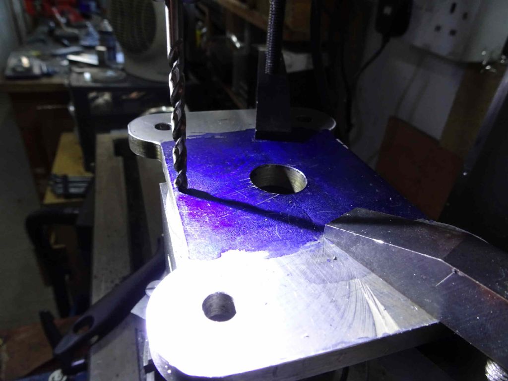
The spigot to hold the cylinder was off centre….
The spigot is 1mm off centre with respect to the edges of the bottom plate.
At this point, I shut down the shed and went indoors. Unusually, not for a glass of comfort (as I occasionally feel a need to let my body recover that this was that day. Sadly).
My first reaction was, Oh bugger!
My second was I can just drill and tap and if it doesn't work I can make a new plate and drill it afterwards.
The third was, 'Did I do this on purpose and have forgotten the reason?' Even I realised that was wishful thinking.
Fortunately a night's sleep put paid to that and I had the thought that I should see if that 1mm actually made a difference.
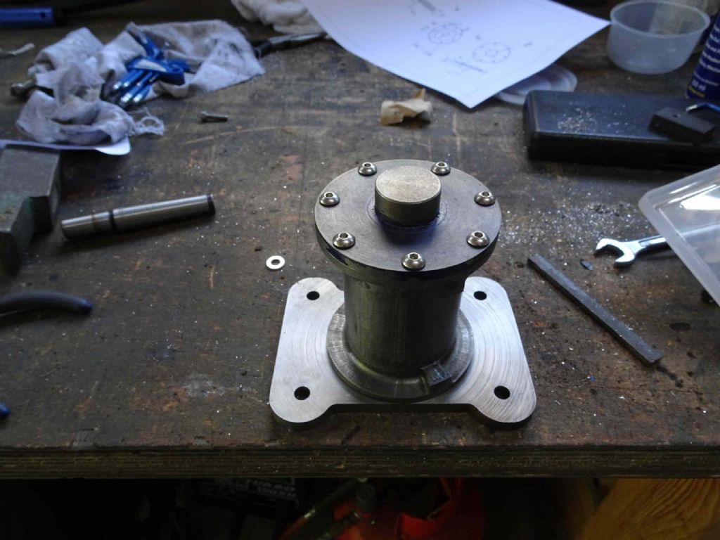
So (for the first time!) I assembled the engine.
I found two things (well two bad things).
I put the piston gland in place with some superglue, by the way so I can get it out easily if it turns out the plate is gash.
The main one was that if I put the cylinder on, it is fine at the top part of the cycle, but jams near the bottom. This is because the piston position is to far to the back at the bottom. Two possible reasons. One is the 1mm offset and the second is that somehow the piston gland bore is NOT in line with the cylinder registration. By about 0.3mm.
I really don't know how I managed that as the two were machined on a superglue chuck which was never removed in the same machining operation (Possibly several days apart, but even so..).
So I've stuffed up the bottom plate well and truly.
Oh, the other minor thing is that my piston gland is to long It stops the piston rising to TDC.
That, at least is an easy fix!
In a perverted way I'm almost pleased this has happened. It's the first major component I'll have to rework and I expected a major screw up much earlier in the process. I'm still terrified I'll accidentally drill a hole in the wrong part of the cylinder. That would be a trial.
So a chastened Downs is going to buy another bit of steel and see if he can learn from his mistakes.
In the meantime, there are the eccentrics to cock up….
Iain
-
AuthorPosts
- Please log in to reply to this topic. Registering is free and easy using the links on the menu at the top of this page.
Latest Replies
Home › Forums › Stationary engines › Topics
-
- Topic
- Voices
- Posts
- Last Post
-
-
What Did You Do Today 2025
1
2
…
7
8
Started by:
 JasonB
in: The Tea Room
- 33
- 194
-
19 July 2025 at 20:31
 JasonB
-
Polishing compounds for stainless steel (mild abrasives))
Started by:
Simon Williams 3 in: Beginners questions
- 2
- 2
-
19 July 2025 at 20:30
bernard towers
-
Diving in to ATC?
Started by:
Steve355 in: CNC machines, Home builds, Conversions, ELS, automation, software, etc tools
- 2
- 3
-
19 July 2025 at 20:21
Steve355
-
Boley 6LZ, new to me
Started by:
Wade Beatty in: Manual machine tools
- 1
- 1
-
19 July 2025 at 19:52
Wade Beatty
-
Boxford paint colour
Started by:
 Pete.
in: Workshop Tools and Tooling
- 5
- 9
-
19 July 2025 at 19:05
 Michael Gilligan
-
Taylor Hobson cutter grinder modificaton
1
2
Started by:
 David George 1
in: Workshop Tools and Tooling
- 9
- 36
-
19 July 2025 at 18:41
 Michael Gilligan
-
More BBC Masterchef woes…
Started by:
 Nigel Bennett
in: The Tea Room
- 4
- 4
-
19 July 2025 at 18:35
Plasma
-
Bad design, or am I missing something?
Started by:
half whit in: Beginners questions
- 3
- 3
-
19 July 2025 at 17:19
 Michael Gilligan
-
Even the Dealer Didn’t Know!
Started by:
Chris Crew in: The Tea Room
- 15
- 19
-
19 July 2025 at 17:04
Bo’sun
-
Paint stripper does not do what it says on the tin
Started by:
Greensands in: Hints And Tips for model engineers
- 5
- 10
-
19 July 2025 at 17:00
 Dave Halford
-
Easiest/cheapest source of R8 socket
Started by:
Beardy Mike in: Workshop Tools and Tooling
- 13
- 24
-
19 July 2025 at 15:20
 JasonB
-
Sat nag
1
2
Started by:
duncan webster 1 in: The Tea Room
- 23
- 47
-
19 July 2025 at 12:28
Howard Lewis
-
New member
Started by:
 Dave Lewis
in: Introduce Yourself – New members start here!
- 3
- 3
-
19 July 2025 at 12:01
Howard Lewis
-
Boiler Design – issue 4765
1
2
…
8
9
Started by:
Charles Lamont in: Model Engineer & Workshop
- 27
- 213
-
19 July 2025 at 11:13
duncan webster 1
-
Please direct me to where I can find an engineer to do some bespoke work
Started by:
srb1 in: Beginners questions
- 5
- 9
-
19 July 2025 at 10:44
duncan webster 1
-
How many spokes do I really need?
Started by:
 Fulmen
in: Related Hobbies including Vehicle Restoration
- 8
- 21
-
19 July 2025 at 07:30
 Fulmen
-
Model Engine running just off a naked flame
Started by:
 Blue Heeler
in: Stationary engines
- 3
- 5
-
19 July 2025 at 04:57
 Blue Heeler
-
Herbert B drill information?
Started by:
Andrew Tinsley in: Workshop Tools and Tooling
- 4
- 11
-
18 July 2025 at 20:23
Andrew Tinsley
-
Which lubricator do I need
Started by:
Michael Callaghan in: Locomotives
- 3
- 4
-
18 July 2025 at 19:53
duncan webster 1
-
Backplate studs
Started by:
Dalboy in: General Questions
- 5
- 7
-
18 July 2025 at 19:46
Dalboy
-
William Hazeldine … Proving Machine
Started by:
 Michael Gilligan
in: Materials
- 5
- 8
-
18 July 2025 at 18:47
 Michael Gilligan
-
Measuring a double Vee lathe bed Vee position
Started by:
Kim Garnett in: General Questions
- 11
- 21
-
18 July 2025 at 15:26
Pete Rimmer
-
Advice to machine stationary engine base plate
Started by:
Greg H in: General Questions
- 5
- 11
-
18 July 2025 at 13:26
 JasonB
-
“swedish iron”
Started by:
moonman in: Materials
- 16
- 24
-
18 July 2025 at 13:06
Martin Johnson 1
-
Electronic leadscrew pitching error
Started by:
 paulg 1
in: Introduce Yourself – New members start here!
- 4
- 23
-
18 July 2025 at 10:32
 JasonB
-
What Did You Do Today 2025
1
2
…
7
8
-
Latest Issue
Newsletter Sign-up
Latest Replies
- What Did You Do Today 2025
- Polishing compounds for stainless steel (mild abrasives))
- Diving in to ATC?
- Boley 6LZ, new to me
- Boxford paint colour
- Taylor Hobson cutter grinder modificaton
- More BBC Masterchef woes…
- Bad design, or am I missing something?
- Even the Dealer Didn’t Know!
- Paint stripper does not do what it says on the tin


 .
.