Steam Engine Number One
Steam Engine Number One
Home › Forums › Stationary engines › Steam Engine Number One
- This topic has 207 replies, 23 voices, and was last updated 7 February 2022 at 12:58 by
 Andy_G.
-
AuthorPosts
-
20 May 2019 at 09:04 #410039
Iain Downs
Participant@iaindowns78295My soldering still sucks.
Here is a charming little travelogue of my adventures with a simple soldering task.
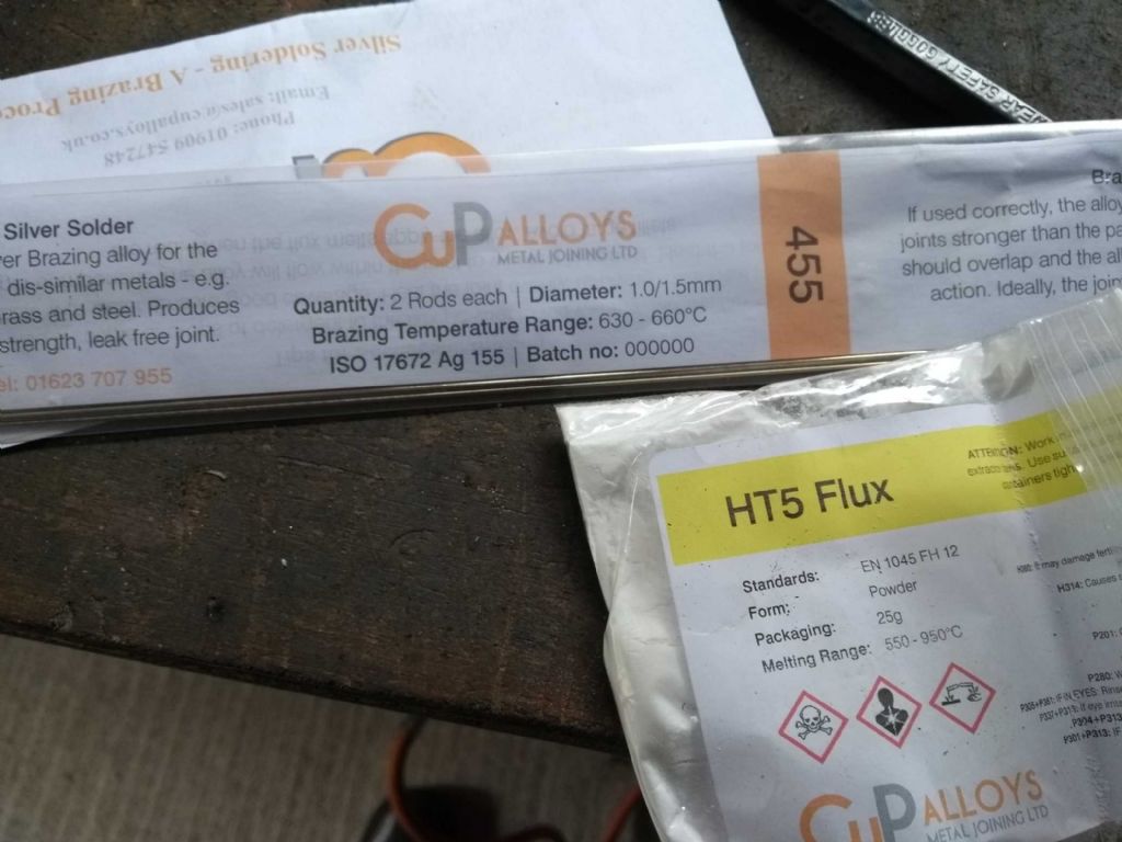
The Solder
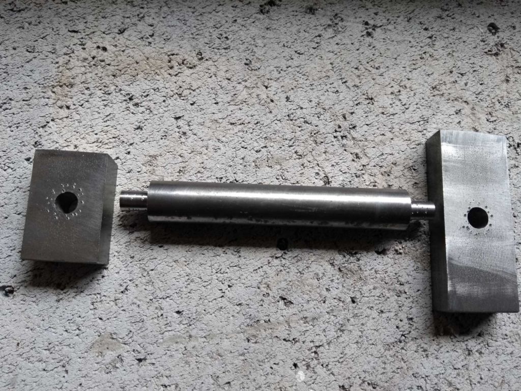
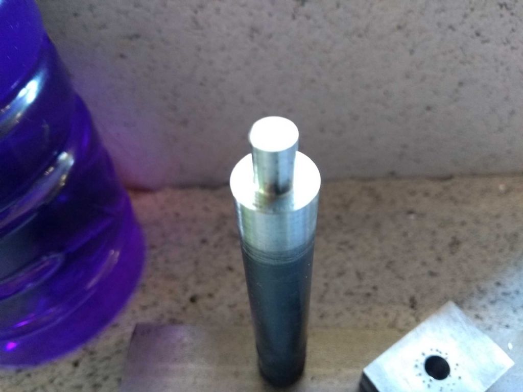
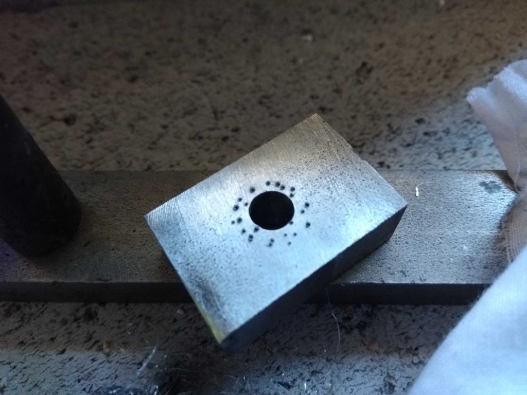
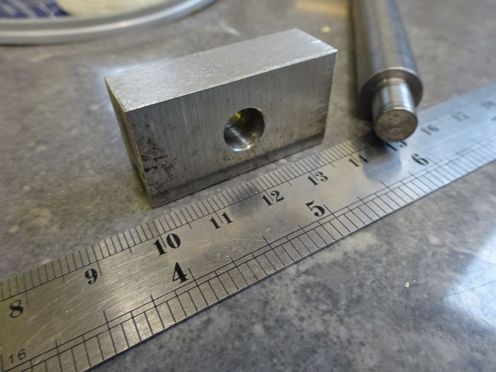
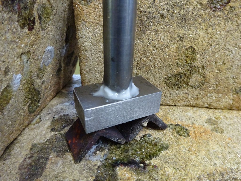
The Parts. The rod is 12mm, the bar is 10×20.
You will notice the dimples. One of the debates in the forum is if you need to use a centre punch to make little dimples to make sure there was space for capillary action. I have no idea if this is a good idea or not, but it kind of made sense.
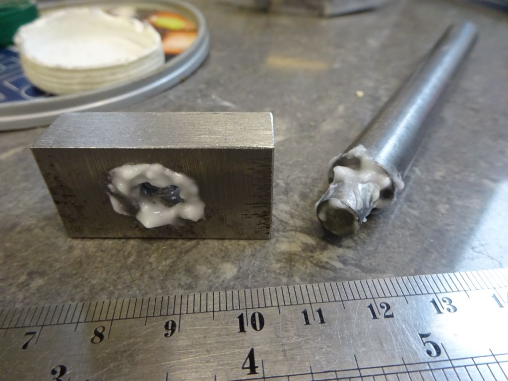
The the fluxing. I'm not terribly happy with the fluxing. 'Consistency of cream'. Cream this lumpy would go down the sink. Not sure How I can get it smoother or stickier.
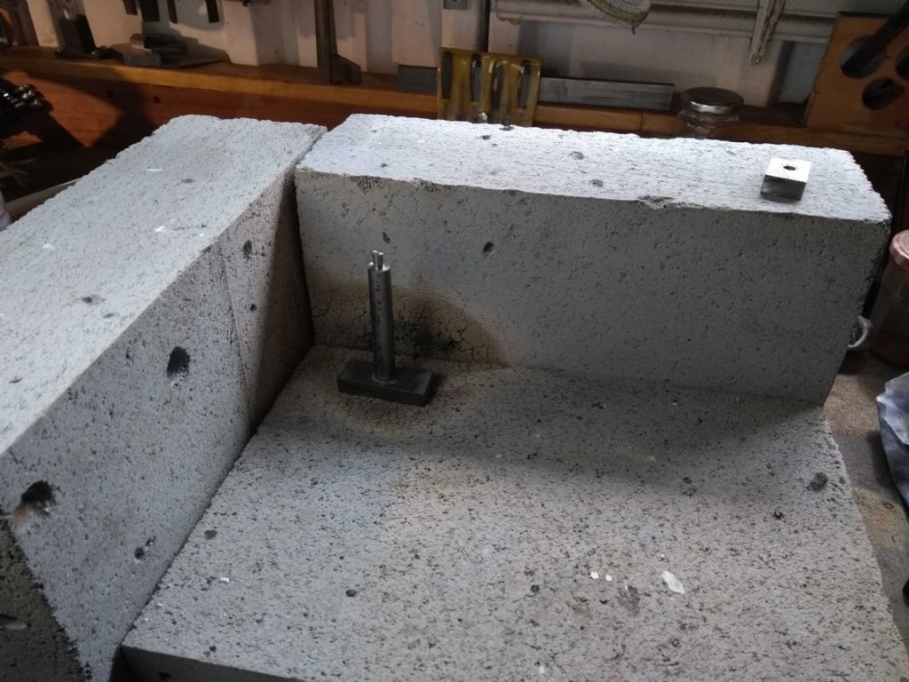
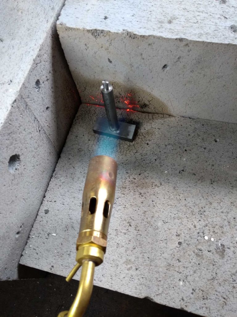
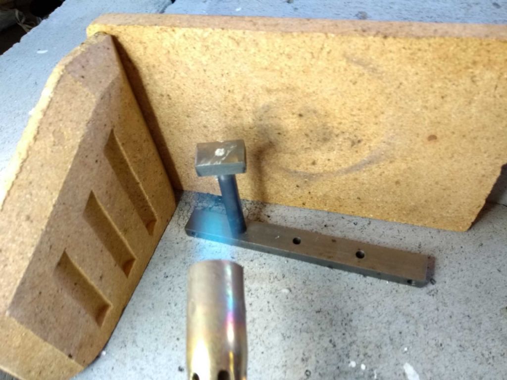
This is my hearth
and I warmed it first
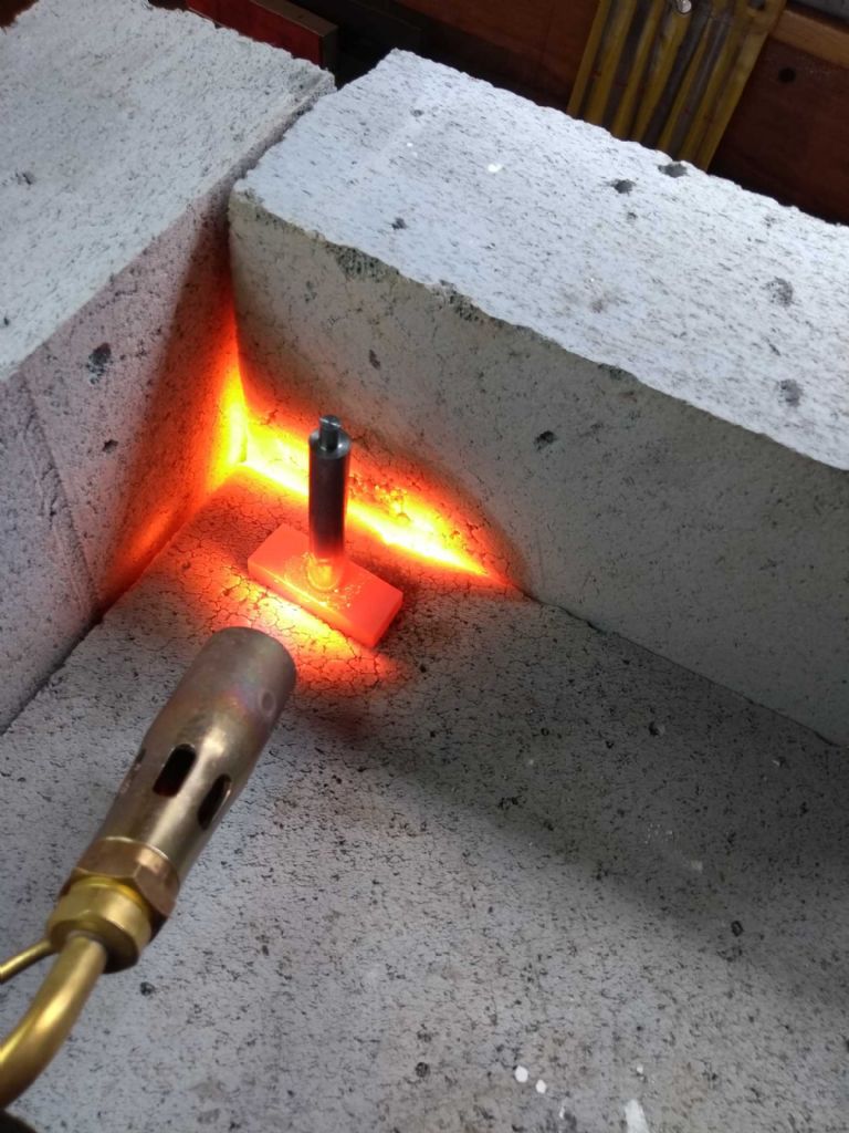
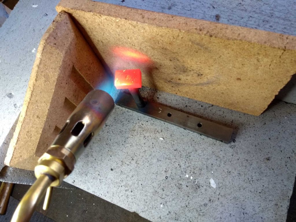
Then blasted away. I was expecting a more defined cone on the flame to be honest, though I'm not quite sure why.
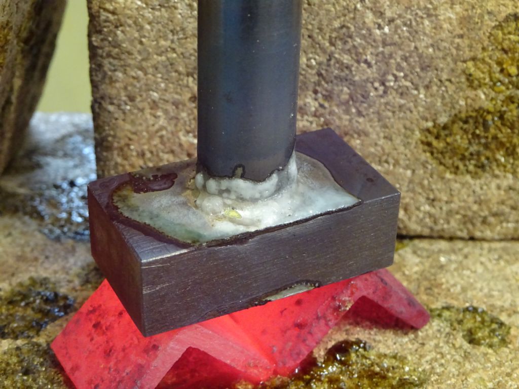
The above is about where I gave up. The solder did not appear to melt when touched to the metal (but see later picture) and formed little blobs when I applied the torch. Between the first image with the torch and this was a little over 5 minutes. I do have a series of photos showing the thing heating up, but I don't really see the point of adding those.
I started trying to apply the solder when it started actually glowing and every so often thereafter.
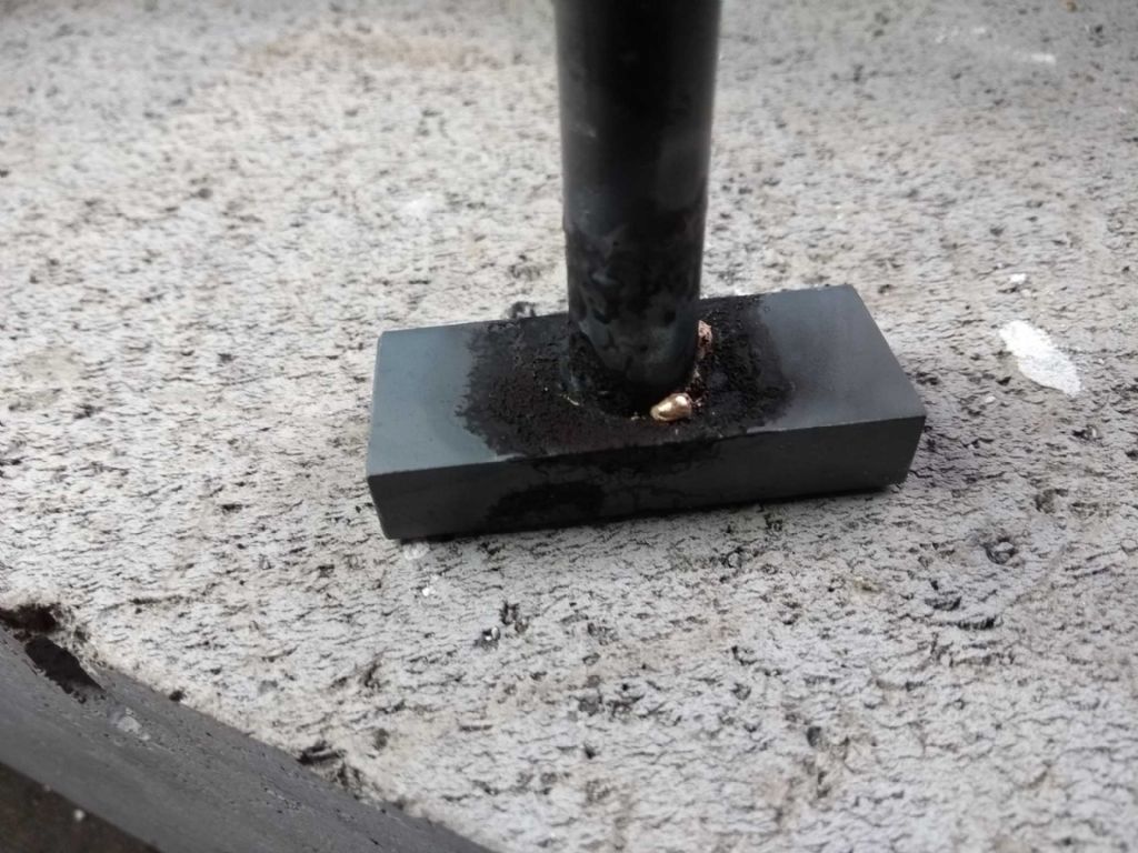
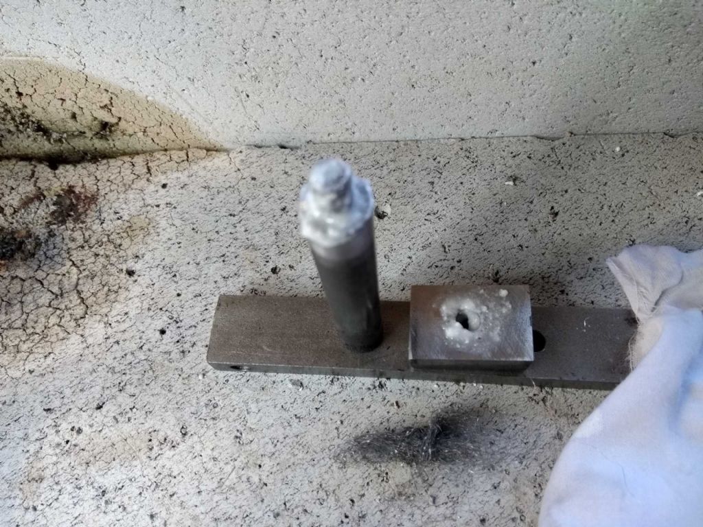
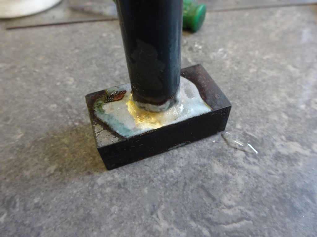
This mess is the result.
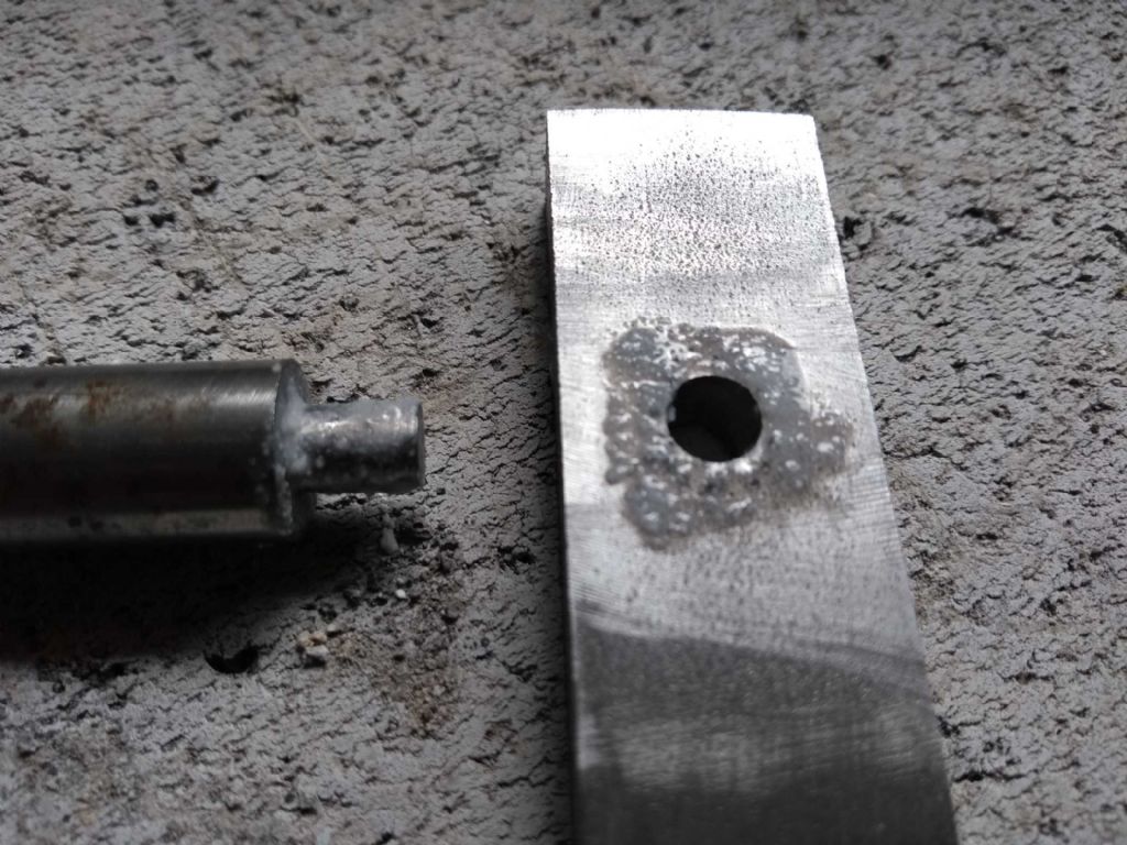
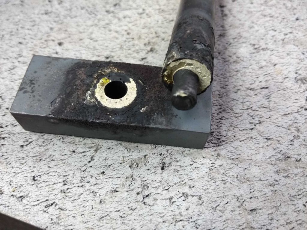
Finally I turned this upside down, but it in the vice applied a drift and a few moderate strikes with a small hammer slit it out as here.
It looks like some solder has crept in, but the joint strength is minimal and the solder has not run down the spigot at all.
This is the smallest of all the joints. the crosshead will have quite a bit more metal than this little bar so if I can't get this to temperature then that will be impossible.
Or am I getting it too hot? Or wrong flux. ARGGHHHH!
The joys of ignorance. Not.
As usual any help would be very much appreciated. I have the other end of the rod and another bit of bar just waiting for my next practice.
Cheers
Iain
20 May 2019 at 09:44 #410044SillyOldDuffer
Moderator@sillyolddufferI hesitate to offer advice Iain because you and I might as well be twins. I think soldering is one of those jobs were everything has to line up just so.
The purpose of flux is to prevent the base metal from oxidising. It mainly contains a chemical that reacts with the oxide, but also makes a temporary layer to keep air out, and it helps transfer heat into the joint. All these effects are time-limited, and any dirt is bad news.
You might be taking too long heating the job up to solder temperature – by the time the job is hot enough, the flux has absorbed all the oxygen it can, and is leaking air. The surface oxidises just before you apply the solder and spoils the joint.
With my smallish torch I've found it helpful to contain the heat better by adding a side and partial roof to the hearth. With an open hearth, as shown in your photos, a lot of heat escapes. I think a big torch makes it much easier to get joints to temperature simply because it has the oompph necessary to work quickly even when the hearth leaks heat badly.
I suspect my other issue is generally poking about and dithering whilst waiting to misjudge the temperature. Watching a chap at an exhibition, I was struck by the smooth speed at which he worked – perhaps three times faster than me, and far more confident.
Dave
20 May 2019 at 10:49 #410054Weary
Participant@wearyHello Ian,
First-off CuAlloys publish a very good guide to silver-soldering.
But, apart from that -> My suggestions:
Actually your work doesn't look too bad at all. You have plenty of heat, even too much, so simple refinement of technique should resolve the minor issues. The devil is in the detail!!
Your Flux: Looks serviceable tho' could be a bit thicker, maybe add a tiny amount of washing up liquid to it to assist 'wetting'. For the quantity that you have made I would get a tiny smear/drop on a pin and add that.
Your 'Work': Needs to be absolutely clean. I do a fair amount of silver-soldering of steel. I de-grease the parts thoroughly ('Gunk' or commercial cleaner from 'Screwfix' ) and then abrade the areas to be joined (wire-wool would be suitable in this case) to physically clean them and then immerse the parts or at-least areas to be soldered in dilute Brick-cleaner (10%) for ten minutes or so. Rinse clean in water, dry and apply flux promptly. Note that experts will tell you that these stages are not necessary, but I have found that oil contamination and to a lesser extent physical dirt can be a right pain and makes the flux work hard unnecessarily.
Heating: Do not 'pre-heat' or 'warm the job'. Get in there with the flame. It also looks to me that your flame is too close to the work. In the pic where 'everything' is glowing it appears to me that the flame could be moved back a little and you would be applying heat more efficiently.
The Work itself. Your creating of dimples on surfaces to be joined is a good idea. I would have soldered that job the other way up and placed it closer to the corner of the hearth. Try and get the area to be soldered off the base of the hearth, maybe using broken fire-brick, bits of 'scrap' etc. with as little contact with other material possible If the job was inverted then all the heat would have been going into the joint and you could get your flame further around the work for most efficient heating. The work would be rested 'upside down' to how you placed it across the corner of your hearth resting on the corners of the oblong section to reduce contact to the minimum. Looks to me like your oblong part used as 'base' didn't get hot-enough, hence lack of flow.
Was there space around your 'spigot' or was it a tight fit in the hole? Some clearance is required, tho' the solder you have flows like water at the right temperature.
If I had the work inverted I would have created a small champfer around the 'hole' to 'guide' the sliver-solder.
Soldering: Speed (and confidence!) is of the essence really. An option is to put a tiny piece of silver solder on the joint where you can see it before heating. Warm your solder-rod and dip in flux. Now heat the job…speedily. With that work inverted I would be heating the work with the flame angled from slightly below the joint focussing on the oblong part and rod to be soldered, moving the flame up and over the part occasionally……. your flux will bubble and clear, then your solder will melt; maybe into a tiny ball = you are near temperature… suddenly solder will flow. remove flame, add solder stick. Add heat if necessary….. Solder will flow to the hottest part whilst flux is still active. But note that there is no point whatsoever further heating the joint once the solder has flowed where you want it.
Job should be 'done'.
If the bubbling of the flux displaces the solder 'indicator' piece then allow the flux to dry before soldering.
Anyway, others will be along with other suggestions.
Regards,
Phil
Edited By Weary on 20/05/2019 10:50:59
Edited By Weary on 20/05/2019 10:55:19
Edited By Weary on 20/05/2019 10:56:56
20 May 2019 at 12:53 #410070 JasonBModerator@jasonb
Off out but a few quick comments, building blocks are not Ideal as they don't reflect any heat, better than denser materials but better used as a backup with vermiculite or Scamolux blocks for the main heating area.
Burner looks too close to the work so you are not using the hottest part of the flame.
Flux looks a bit watery and as I said earlier if it is EF flux may be getting exhausted before temp is reached due to points above.
20 May 2019 at 14:07 #410085mechman48
Participant@mechman48My small hearth comprises of 5 vermiculite blocks & blanket ( Cup Alloy ) 4 block for the walls & 1 to form a 'roof' if needed… The largest heating rig I have is the Propane/butane system bought from B & Q which so far has provided enough heat for the small tasks I have done… usual disclaimers apply…
George.
22 May 2019 at 19:07 #410446Iain Downs
Participant@iaindowns78295This is a MULTITASKING post. My good lady is quite convinced that neither I nor any creature with a willy is capable of doing more than one thing at a time. Hah!
I will leave the soldering out of this post. The last go seemed better than previously, and I've got the result in a citric acid pickle which is gradually getting the scale off. It looks like the solder has seeped through at the moment, but I'll wait till it is clean. I've also put some other failed test pieces in so I can retry with a few of them when cleaned up.
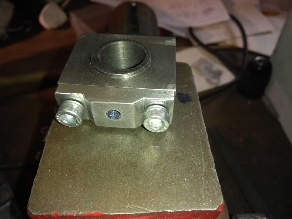
The other main task was finishing off the big end bearing and the big and to con rod connector.
The bearing was done, but needed to be reduced in height.
My new vice is making life easier. I have an item on my todo list to make some locators to fit under the vice and in the table to avoid having to align all the time.
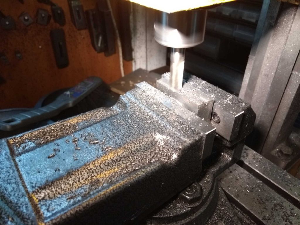
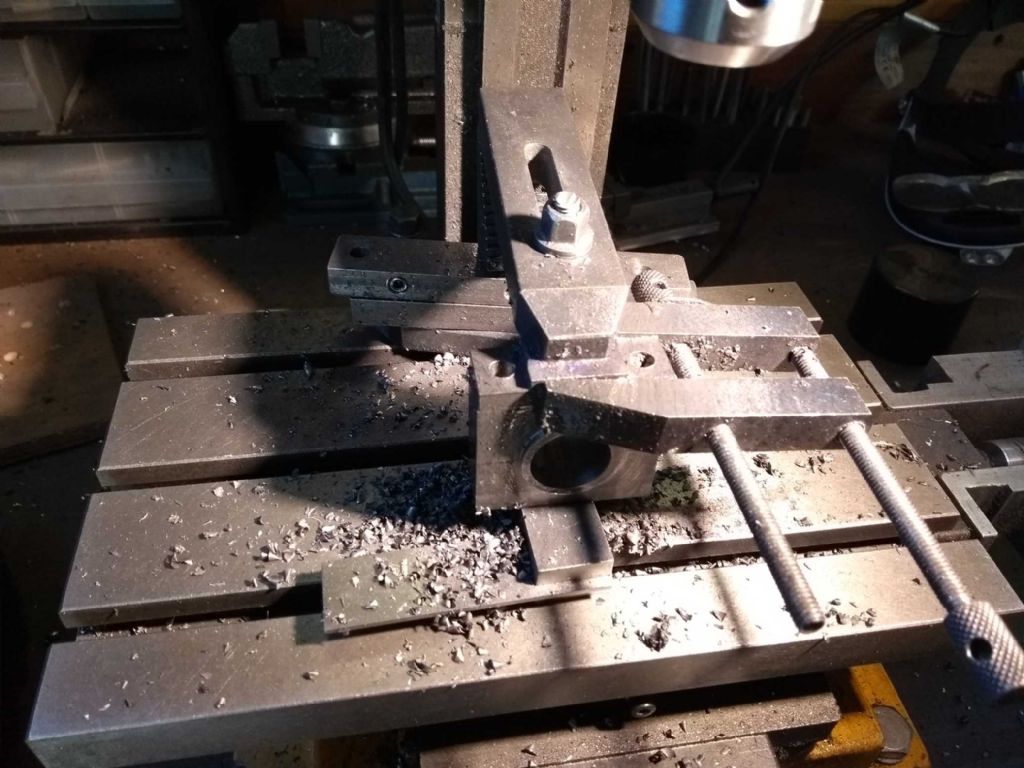
Having trimmed, I then clamped the connector on top of it, centre drilled and the drilled each bolt hole with a 5.8 mm drill.I'm not sure that the heath robinson clamping arrangement would have found it's place in Jason's (excellent) article, but it seems to have worked.
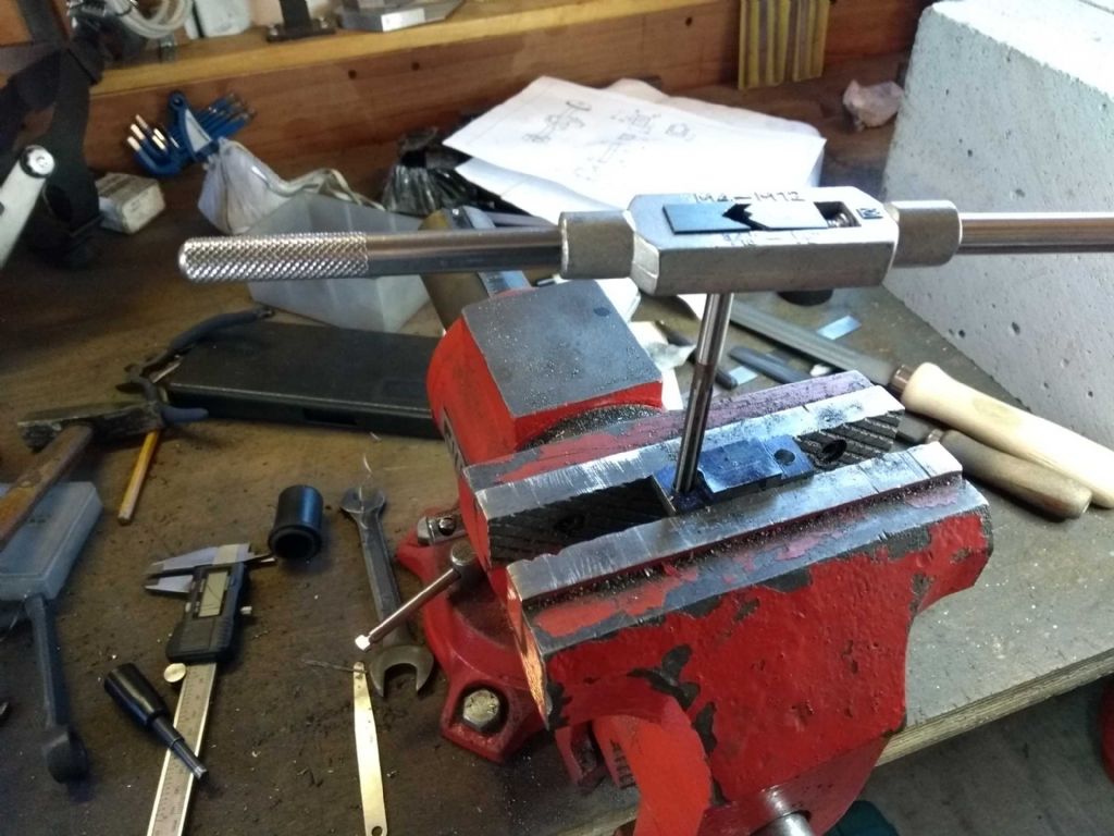
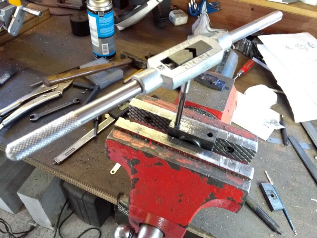
Next the bracket reamed to 6mm
and the same for the bearing
next step was to file an angle on to the bracket – partly aesthetic and partly to get rid of nasty square corners and then put the bits together!
In an upcoming episode I shall scrape the bearing against a piece of sliver steel. I suspect I will do this against the bit that's NOT in the crankshaft is it should be pretty exactly the same size and be a lot easier to deal with.
But, Iain, you said MULTI-tasking? Surely this is BI-Tasking at best. Well, during this period I also started to plan out the machining of the cross head and to cut-off a 60mm long piece of 40mm square bar. Sadly, this has blown up my Aldi chop saw and I had to finish off the last third by hand. Ugh.
So at the least TRI-tasking.
Iain
24 May 2019 at 13:42 #410730Iain Downs
Participant@iaindowns78295So back to soldering. I followed pretty much all the advice and this time it looks to have worked! I will need a few more goes before being confident, but thumbs up so far. I'm not entirely sure which 'advice' made the difference – or possibly a collection of changes. Still…
Firslty, the rod and block were sanded and wire-wooled and cleaned with meths.
and
I'd thickened the flux up, but I was still expecting something smooth (like the so often described cream), but it remains a powder suspended in water – lots of lumps. Is this right?
I originally bought firebricks (from a domestic fire) but for some reason thought that they were absorbers of heat not reflectors so got these bricks instead. Looks like I was wrong.
This time I'm soldering upside-down (the piece – I stood upright, it's hard enough as it is!).
I'd also turned the regulator up to 7 and got a little more flame which I kept further back. It also seemed to make a nicer cone.
I'd put a little curl of solder in the hollow at the top and at some point (probably about 4 minutes in ) it disappeared – into the join. It was only a little bit so I added some more. I still wasn't able to get the solder to melt just by touching it to the hot metal (which all my books say is right), but with some flame it would melt and I guess capillary in.
I know I said I'd heated it from underneath, but I brought the flame up as well occasionally – the block is the bigger heat sink.
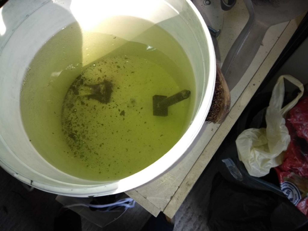
I'd also spread my research wider and found I could 'pickle' the assembly. I'd bought 1kg of citrix acid which I dissolved in about 4 – 5 litres of hot water. I was expecting it to become saturated, but think I need even more.
Her is the piece in the pickle bucket.
It was in the bucket for about 2.5 days before I got bored and took it out and rinsed. The scale has largely gone, but the metal rusted very quickly after being rinsed. Should I have left the pickle on? Should I have left it in for longer? What's a sensible amount of citric acid for a bucket (3.5 litres of water?). Can I filter the nasty bits out or do I need to throw the lot away?
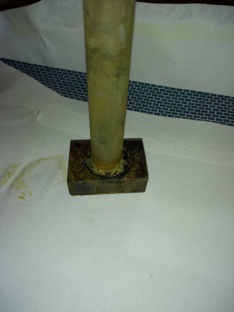
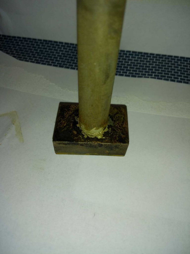
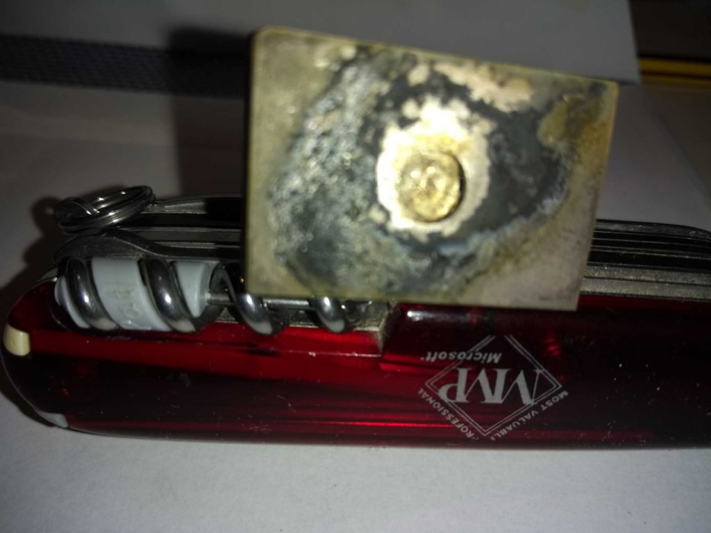
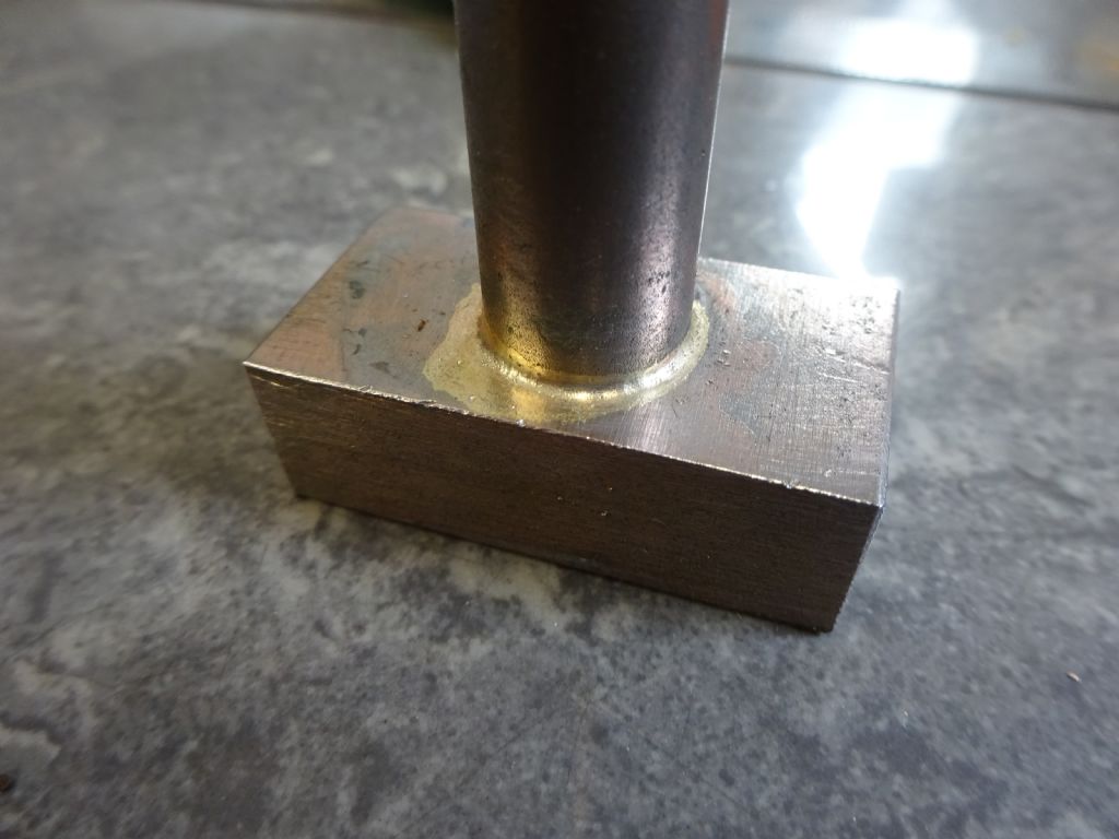
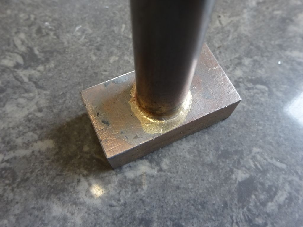
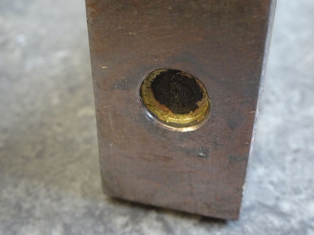
And here we have the results.
Front and back views of the top of the join
and the underneath view of the block.
One of the challenges with coming into this sport is that you don't really know what to expect. For example, I had to heat this assembly for 4 – 5 minutes before the solder ran. I had the impression that this would happen much quicker. And I don't really know at which point the solder should run – what colour should the metal be? And if I want to use Low and High temperature solders to assemble a complex piece, How do I know which colour to aim for aim all cases?
I suppose the practical answer is clear – and I'm already applying the technique – trial and error! Try often enough and instinct starts to work …

Today's task is to start milling out the cross head – assuming that is that I can persuade myself that that will be more fun that sitting in the sun reading a book..
Iain
24 May 2019 at 15:02 #410740SillyOldDuffer
Moderator@sillyolddufferPosted by Iain Downs on 24/05/2019 13:42:19:
…
I'd thickened the flux up, but I was still expecting something smooth (like the so often described cream), but it remains a powder suspended in water – lots of lumps. Is this right?
I originally bought firebricks (from a domestic fire) but for some reason thought that they were absorbers of heat not reflectors so got these bricks instead. Looks like I was wrong.
…
I'd also spread my research wider and found I could 'pickle' the assembly. I'd bought 1kg of citrix acid which I dissolved in about 4 – 5 litres of hot water. I was expecting it to become saturated, but think I need even more.
It was in the bucket for about 2.5 days before I got bored and took it out and rinsed. The scale has largely gone, but the metal rusted very quickly after being rinsed. Should I have left the pickle on? Should I have left it in for longer? What's a sensible amount of citric acid for a bucket (3.5 litres of water?). Can I filter the nasty bits out or do I need to throw the lot away?
…
One of the challenges with coming into this sport is that you don't really know what to expect. For example, I had to heat this assembly for 4 – 5 minutes before the solder ran. I had the impression that this would happen much quicker. And I don't really know at which point the solder should run – what colour should the metal be? And if I want to use Low and High temperature solders to assemble a complex piece, How do I know which colour to aim for aim all cases?
I suppose the practical answer is clear – and I'm already applying the technique – trial and error! Try often enough and instinct starts to work …

Iain
Gritty flux rather than Dairy Double Cream is what I get.
Using the wrong firebrick will cause trouble if your torch is on the small side. Insulating firebricks are usually light and soft, absorbing firebricks are heavy and hard. The heavy absorbing type are NOT what you need. Don't guess, get the right type. (Or a much more powerful torch!)
Pickling: Dilute Sulphuric Acid if you can get it is best because it is fast and cheap. Minutes rather than hours. Citric Acid is a lot slower (overnight). How fast scale is removed depends on the concentration: your mix was weak, try for about 1:1 by weight, ie 1kg of Powder to 1 litre of water. Heating the water will allow a higher concentration and speed the pickling reaction up. Once by inspection the acid has cleaned the scale off, mild-steel reacts immediately with air. The trick is to clean the pickle off get soldering the metal as soon as you can. Keep using the acid until it stops cleaning metal or goes off (Citric Acid is biodegradable!) No particular reason to filter it.
I think you're doing the right things, but likely too slowly. How to fail: buy an ordinary DIY blow-lamp with a low heat output. Build a leaky heath out of heat absorbing brick. Then take two hefty lumps of rusty steel, apply a thin watery layer of flux, and poke at the job with a wobbly flame for far too long before applying the solder. The small torch is hot enough to activate the flux, but not powerful enough to get the metal up to temperature quickly, especially if the operator has L Plates. By the time the metal is hot enough to melt solder the flux has failed, scale reforms, and you get a dud joint.
Trial and error teaches you to get everything right quickly, it's experience not instinct. A beginner would probably do better starting with a big torch because getting a small one to do the same job needs more skill. I'm too mean to buy a big torch, and my results are intermittent. I'm much more likely to succeed soldering smallish lumps than big ones, and I believe the reason is the extra time bigger jobs take to get hot.
Dave
24 May 2019 at 15:50 #410751 JasonBModerator@jasonb
If you want to use punch marks then three evenly spaced ones will do the job.
Add as much powder to the water as you can before it won't dissolve any more though it will take a long time with such a mild acid, Brick and patio cleaner will do it in 1/2hr but don't forget you have something in there or it may get eaten. Just let the muck settle and decant the clear stuff, discard the bit in the bottom.
When you take it out of the pickle rinse in water and give a scrub with a small wire brush, dry and spray on a bit of WD40 straight away.
Flux will first bubble to a white throth, then becomes a sticky melted sugar consistency then it will flow as a clear liquid at which point you are upto temperature. I'll photograph a bit of mixed up flux over the weekend for you
24 May 2019 at 16:14 #410755Iain Downs
Participant@iaindowns78295Thanks, both.
Dave – I have a Sievert Torch (recommended in this forum) because it should be powerful. Your comments on the firebricks are well taken, though with the arrangement I had I don't think they did much. Looks like some replacements or on my shopping list which may reduce the time to heat up.
Jason, would this stuff do? Some patio cleaners claim to be acid free, but I thought acid is what I wanted. I picked this one as the cheapest at B&Q!
I am impatient (well sometimes) and also absent minded these days. Which puts me in a real spot. I would like the speed of brick cleaner, but the chances of me leaving some things in too long (days!) are quite high. I will probably take my chances.
Your note on the clear liquid for of the flux is very helpful. I shall look for that with my next practice.
My poor Mill has blown a cog again (I need to reduce a 40x40x60 to 30x40x60). It was going pretty well with a 17mm face mill and .5mm depth. then it started to overload and then spin. I think that it's got overheated in the gearbox which has weakened the gears. Then off for a few glasses of optimising fluid (red in nature).
Iain
24 May 2019 at 16:55 #410764SillyOldDuffer
Moderator@sillyolddufferI thought all Patio Cleaners were based on Hydrochloric Acid. Apparently times have changed! It now seems most Patio cleaners don't contain acid of any type and – like the Swarfega example – would be useless as a pickle.
The right stuff is still available. Look for Acid Brick, Mortar or Patio Cleaner like this example on Amazon.
Though it's fast acting I'm not entirely happy with Hydrochloric Acid as a pickle though. I've read it leaves chloride ions trapped in the pores of steel that cause rust later. Even under electro-plate or good paint. If used and corrosion is a concern, give the steel an extra thorough cleaning.
By the way, no need to pickle freshly machined steel. It's plenty clean enough to make life easy for the flux. Pickling might even make things worse, especially if the wrong chemical is used.
Dave
24 May 2019 at 17:33 #410776 JasonBModerator@jasonb
This is the stuff I get from my local builders merchant, Feb products should be easy enough to find.
25 May 2019 at 10:48 #410874 JasonBModerator@jasonb
Well as i had mixed up some flux to photograph why stop there!
Piece of unknown steel 36 x 20 x 11 that already had an 8mm hole in it, just sawed it off a bar and cleaned up the flat faces on the belt sander. Piece of unknown 13mm bar turned to fit the hole.
Flux to a thick creamy consistancy (see later video) applied to hole and spigot, no punch marks use on this job. no other cleaning done
Push the two together and make sure there is a good fillet of solder around the job. Raised the work up off the vermiculite blocks which saves the flux sticking to the block and also allows heat under the large lump of steel. Solder won't take to the rusty bits of angle iron which are kept for this type of use.
See video for heating, use dthe same torch and burner as you, my 4bar regulator was fully open. I did use 42% solder you you may need 30secs or so to get upto 55% temps.
taken just after the torch was turned off you can see the flux starting to harden and the clean area of steel where it has flowed can easily be seen through it
After quenching, I don't often quench but a sit was just for a test no need to worry about distortion or hardening unknown metals, extent of solder flow easier to see.
After 20mins in the brick cleaner, the pink tinge is copper from the acid which is a couple of years old, it leaches out when you also use the pickle for copper/bronze and brass but cleans off easily enough.
Finally the proof of the pudding, a nice fillet of solder at the end of the spigot showing good penitration.
Not the best video as it is hard to hold the torch and camera in one hand while waving the solder about in the other. Job is hot enough for solder to flow at 1.36 into the video, a bit cold before that so allowing for the flux shots that is 1min 20secs to get upto heat and a similar volume of steel to yours.
Edited By JasonB on 25/05/2019 10:50:12
25 May 2019 at 11:00 #410876SillyOldDuffer
Moderator@sillyolddufferAngle iron to lift the work so the flame can heat underneath as well! Such an obvious good idea : why don't I think of them?
Thanks again,
Dave
25 May 2019 at 12:44 #410896Iain Downs
Participant@iaindowns78295Firstly, Many thanks for the photos and videos Jason and the various other advice.
When we last left our intrepid engineer, he had retired from the field of battle having broken his long suffering mill and retired to console himself with a glass (or two) of the red stuff.
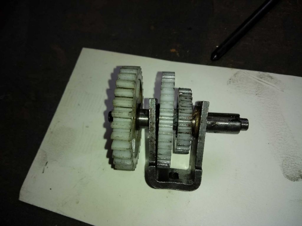
Before I left I took the top of the gear assembly and got the gear shift mechanism out. I had a struggle with this as the mechanism wouldn't shift, but application of a lever helped.
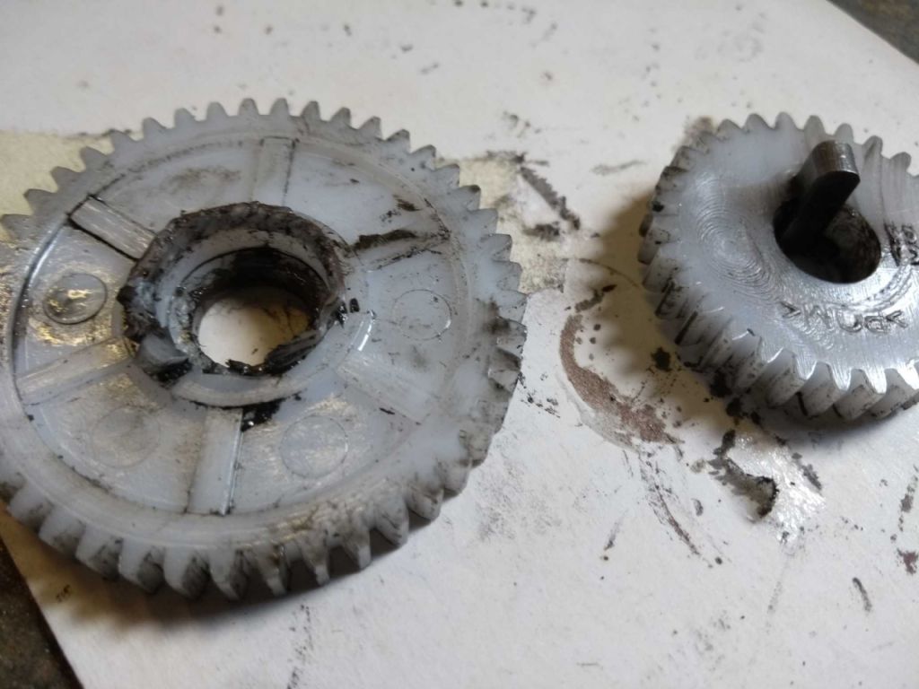
When I got it out, this is what I found.
You can see that the key for high speed gear has shredded the internal bore. At this point I realised I would miss the train soon, so left.
This morning, I found one of my replacements. However, the whole mechanism was tight. I had to smooth out the gear spindle with a bit of 1000 grit paper and open up the working gear (low speed) with a 10mm reamer. In the process I found I had 3 10mm reamers (bought as various sets). One slipped through the hole handily, one struggled to enter and one went in nicely and trimmed the hole! Shades of goldilocks – and not giving me much faith in my eBay bought (cheap) reamers!
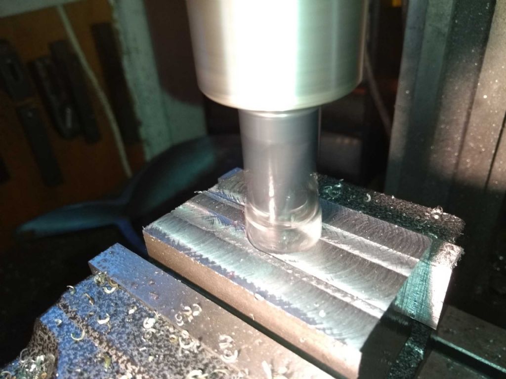
Anyway, I put it all back together and got on with thinning my 40mm to a 30mm. I'm using a 17mm face mill which is at the limit of the spec of the machine (CMD 10 / X1 for those who are new to the thread).
I'm running it at 2000 rpm (top speed as this gives a smoother finish and rattles less. I'm taking off about 0.5mm each pass as here
Things were going so well (thinking new gears, eh!(, that I upped the depth to 1mm, but it did not like this, overloading. So I dropped down to 0.75 mm or so. That worked for a bit, but I saw overloads again,so dropped down to 0.5mm again. And then it broke again.
This time rather more seriously. No, not the motor or control board (phew).
I took the gearbox apart (again!) and this time saw that the forks had spread and the whole mechanism was stuck.
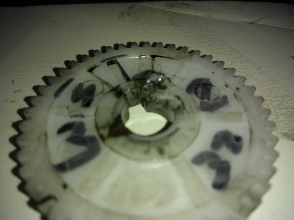
On taking this apart, the high speed gear had again suffered on the inside.
I do have another spare, but first to bring the fork back to straight. You proper engineers can probably guess what came next?!
Yup. Two half forks! I also noticed that one of the bearings had been damaged (it was OK before the mishap).
At this point I abandoned ship and put in a plaintive cry to ARC to deliver some replacements. I'm replacing the whole gear assembly – the spindle, fork, keys and damaged gears as the keyway in the spindle has also visibly spread. All the parts are quite cheap, but they add up!
So no more work on the cross head until they arrive which will likely not before Wednesday or Thursday.
My son suggested I make a replacement, but this did not appeal (no mill, only hand drills and no forge… nah).
I'm a little concerned that the face mill is putting too much load on the gear train. I've regularly being taking 1mm and more off off with a 10mm carbide end mill, so I don't *think* it is the face mill which is the root cause – more likely just general wear and tear. Opinions welcome though.
Iain
25 May 2019 at 13:12 #410904 JasonBModerator@jasonb
Iain, what parentage is the insert that you are using in the cutter?
I bought a 50mm facemill a year or so back and my X3 did not like it one bit with poor finish and lots of really bad vibration shaking teh whole machine. A change to some better quality inserts which cost more than the whole facemill, arbour and 10 inserts solved the problem and it now works well.
Some of the cheap inserts don't have much in the way of a cutting edge which may be OK on a hefty machine that can power its way through but it is just like using a blunt cutter on our lighter machines.
25 May 2019 at 13:49 #410906Iain Downs
Participant@iaindowns78295The facemill came from ARC Eurotrade. Which probably makes it pretty good.
At 0.5mm I get little vibration and a reasonably decent finish. At 1mm I get a bit of vibration and a slightly rougher finish. But the controller keeps cutting out with an overload.
I have more vibration issues at 1000 rpm and I had bigger issues until I turned the (triangular) inserts round and forced them into place.
I think the facemill is OK actually – just that the CMD10 is not the brawniest in the block.
I'm going to see if I can make a start on the cylinder cap now – that doesn't need a mill! And perhaps the piston.
On that, I'm trying to work out the best way of connecting the crosshead, con piston rod and piston.
I am planning to bolt the piston rod and piston together. I will either solder the piston rod to the crosshead or thread the end of the piston rod and tap the crosshead – and secure with a lock nut.
One of my (non electronic) advisors, Richard Gibbon in York, recommended that I bolt the piston to the piston rod and then bash the nut to keep it in place. The idea is that you can then mount the piston rod in a collet and finish the outside spot on for the bore size. That makes some sense, but then I'd need to thread the piston rod so that I could assemble the whole lot through the bottom cylinder plate.
Well, off to discard some perfectly good cast iron…
Iain
Iain
25 May 2019 at 14:05 #410909 JasonBModerator@jasonb
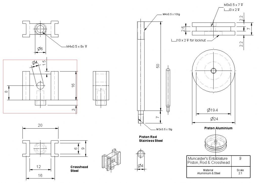
Threaded pod and locknut into threded cross head is a good way to go as it allows some adjustment so you can get the piston travel central of the cylinder. needs a good square thread so best screwcut and if you are using 12mm rod then go for a finer pitch than teh usual M12 coarse pitch. Other option is to turn a spigot say 10mm dia that is a good fit into a bored 10mm hole in the cross head and use a tapered cotter to pull the two together.
Piston end of the rod is best reduced in dia so you have a shoulder to bear against the piston, 8 or 10mm dia would do, part thread this but leave a section unthreaded that can locate in a bored hole in the piston. Piston is drilled and tapped to suit your thread then counterbored to suit the plain section of the spigot. Other side of piston is recessed for a lock nut so it does not hit the cylinder cover.
No need to go bashing your nuts, drop of thread lock will do and as suggested finish turn OD of piston when it is on the rod.
Drawing below shows what I have just describes click to view larger, scale to suit your engine.
25 May 2019 at 15:02 #410916Ian S C
Participant@ianscIf the teeth on the gear are OK, I'm sure a repair job could be done with a metal flanged bush. Perhaps a belt drive would be more forgiving. On my Rexon mill I run my 50 mm face cutter at 940 rpm with .5 mm depth of cut, it will cut to 1 mm, and when I bought the cutter I knew little of milling, and asked the guy in the shop about speeds etc, he just said 950 rpm, a mm depth, and crank like hell. At the moment I'm stuck with 450 rpm, and that's doing most work I need.
Ian S C
25 May 2019 at 15:33 #410922Paul Kemp
Participant@paulkemp46892Iain,
My baby mill is exactly the same as yours and I have suffered several failures too! First time round I split the motor gear so fitted a new one – key was slack so I filed up a new stepped key that was a good neat fit. Second failure was the gear fork breaking completely and similar damage to the gears. Replaced the lot, third time it spread like yours and of course broke when I went to straighten it – so I welded it back together! That drove all the oil out of the bushes so I soaked it for a few days, made a new longer key that spans the gears fully and off we went again. So far, it's still running! My impression is the radiused end on the short key acts like a wedge in the nylon and jacks the gears apart, bending the fork. My new key is full width of the gears and square ended so eliminates the possibility of the wedge effect. Try making your own key with the new gears rather than using the std one, I feel you will get on better! Only needs files and patience!
Paul.
29 May 2019 at 17:12 #411538Iain Downs
Participant@iaindowns78295Hi, Paul,
It's good to know it's not me. I have a bit of a love hate relationship with the poor thing. Initially it veered more towards hate, but after a number of tweaks and adjustments, I've got quite fond of the old dear.
Mind you, I'd swap it for a bigger beasty in an instant (all things being equal).
Iain
29 May 2019 at 17:36 #411543Iain Downs
Participant@iaindowns78295Being as my cross head / con rod progress is stalled pending parts for the little mill, I thought I'd crack on with the piston (whilst the lathe still works…).
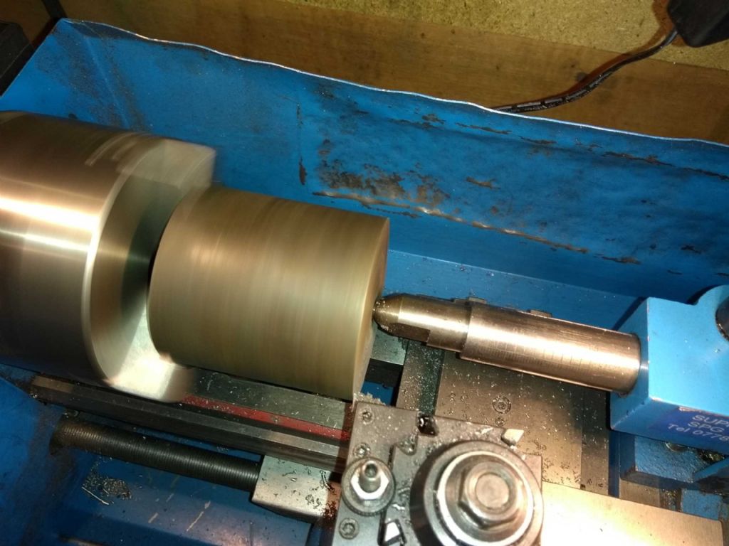
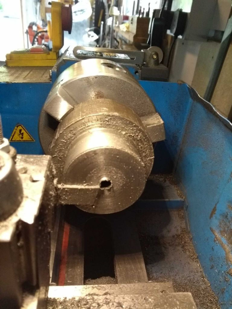
Here we have the chunk of cast iron from which the piston and it's rings will be carver. I used a centre as much as possible throughout this process as the grip from the 3 jaw isn't great and the chunk quite long.
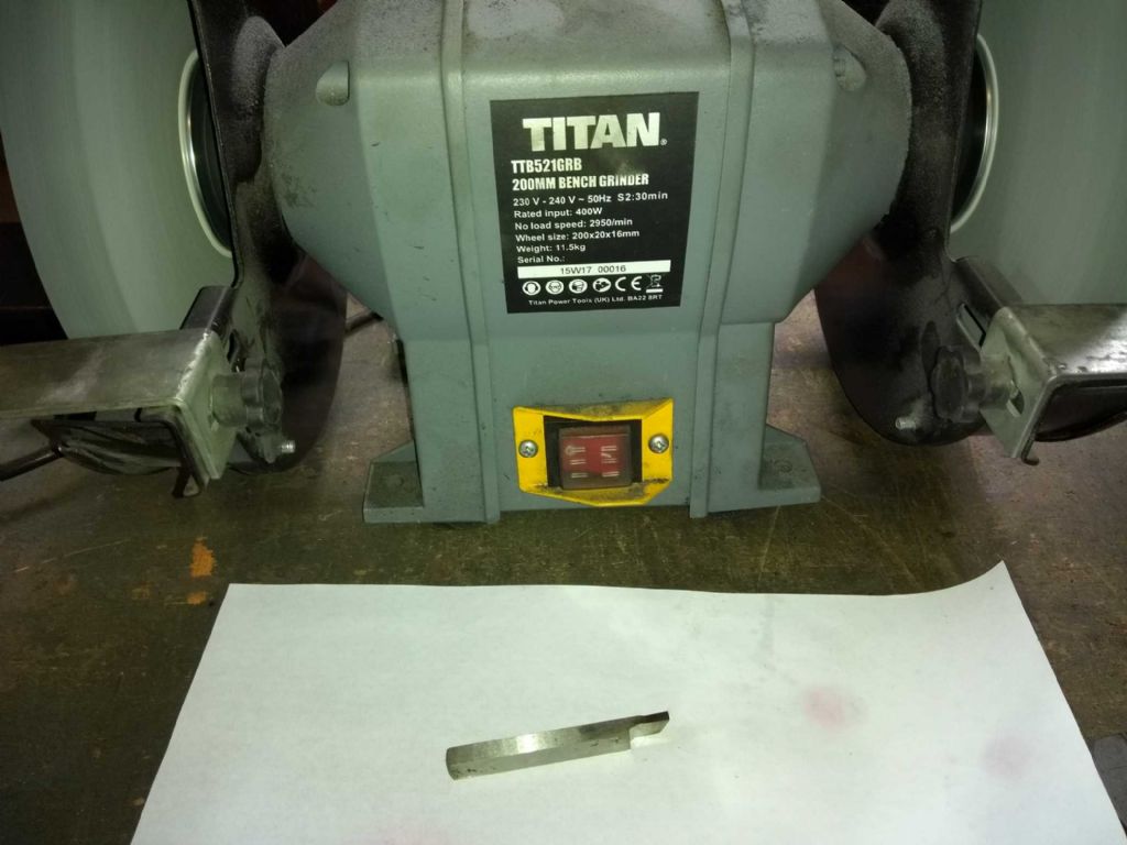
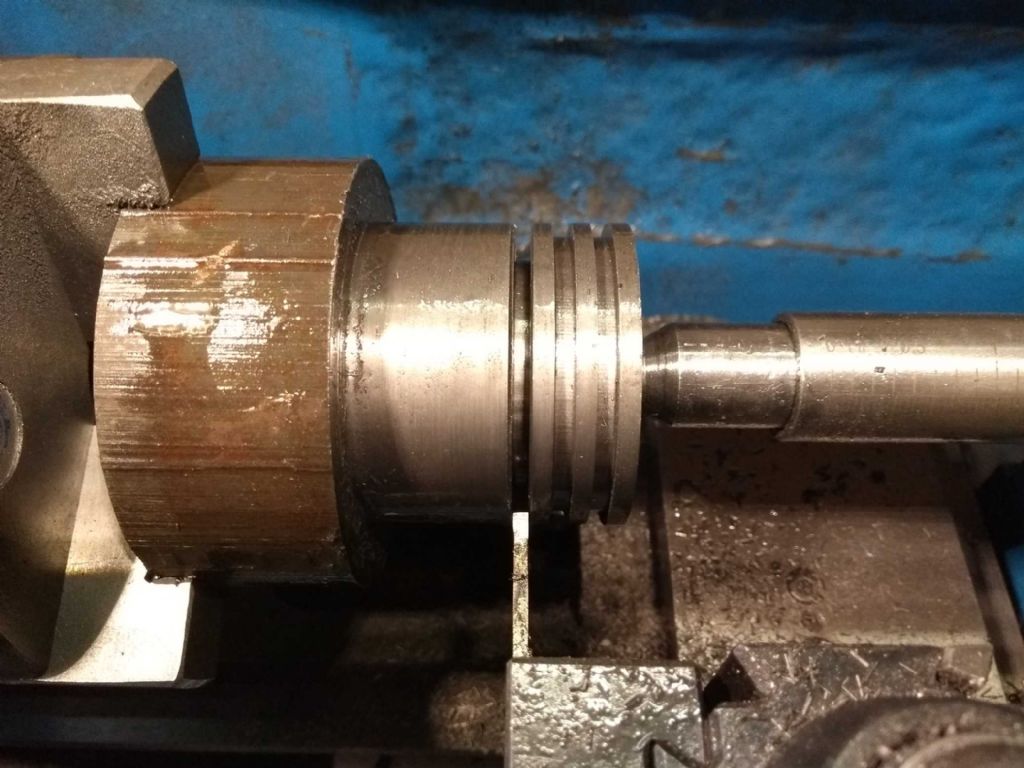
Having trimmed a bit down to a little over 50mm, I then made a grooving tool exactly (for me) 3mm wide.
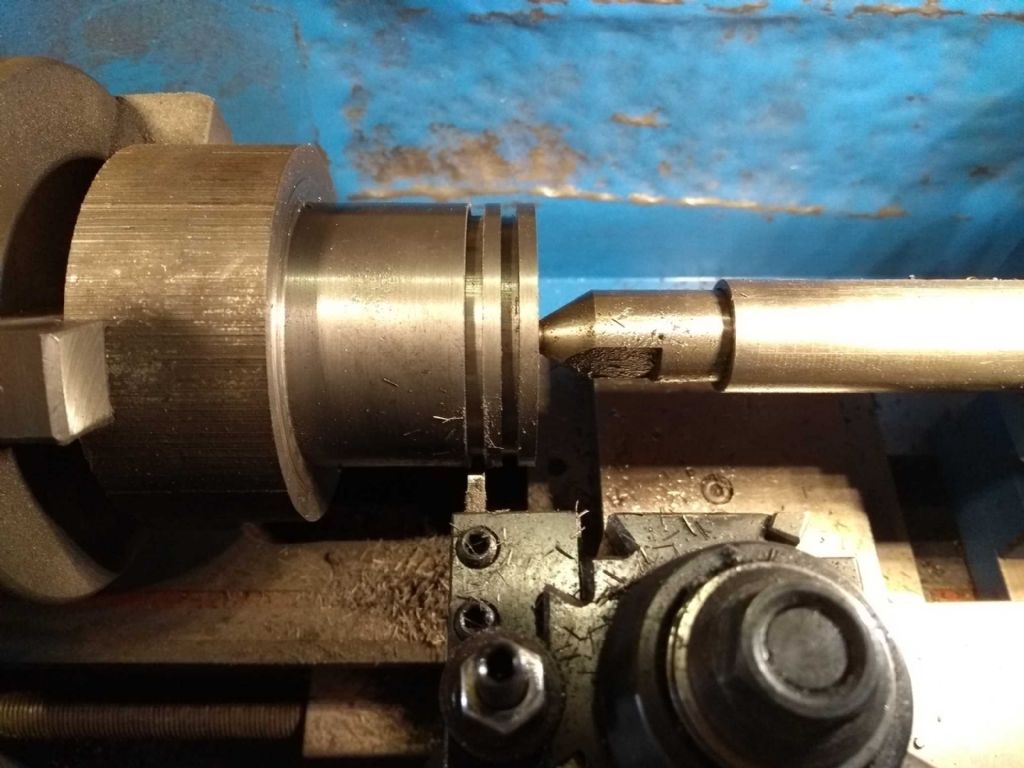
Then the grooving.
A bit of chatter on this – no idea why and not going to affect the performance.
Then. Oh. My. God.
The parting off. For this I took some half inch x 3/16ths HSS (yes I know. Everything else is metric, but this is how I bought it) and added a bit of top rake and some side clearance. I added a bit more later (part way through) and this should have worked.
I was very nervous about the parting off. It's not an area I've had huge success with, though the QCTP made of steel rather than the rubber one (well Ally really) that I had before makes it closer to possible.
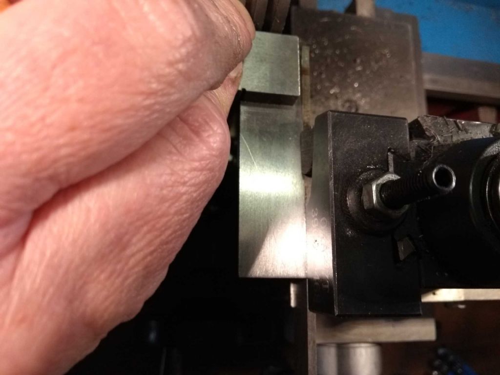
I tried to make sure the parting tool was dead on right angles to the work.
Not my best photo.
you can see some chatter in the groove here. This was a serious issue all the way through. What would happen is that as you fed the tool in it would not do a lot and then start to grab. Sometimes (not too often)this caused a jam which in turn would dislodge the piece from the jaws so I had to loosen push back and re-tighten. After a while I got used to the feeling for this and could pull back (mainly) before anything untoward happened..
Curiously, the cutting got easier the further in to the material I went.
I started off with the tool perfectly (for me) centre aligned, but after a little while dropped it by maybe half a mm which may have helped.
This was a very very cautious parting off. In fact it took the best part of an hour, feeding in a fraction at a time.
Phew!
Sadly, my lathe is not equipped with the means for a back parting tool.
IN the end this was reasonably successful. I've found that the parted end isn't exactly straight. It domes towards the centre. Also my adding up must be wrong, It's about 0.25mm too long. I'm thinking that I'll put it on a stub mandrill and shrink it back to the right size.
Next, the piston rings. I wasn't sure to be scared of these or not. My greatest concern was that I had to finish these to spot on the diameter of the bore. I actually seemed to have got pretty close to that so I'm quite pleased.
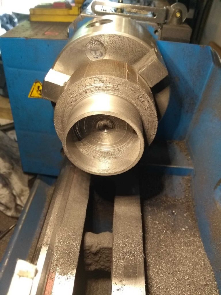
However, we start with yet more discarding of perfectly good metal.
LIke this
2.5 wall thickness with 3mm width rings. I started off with a reasonably chunky indexed carbide bar but finished of with an hss tool.
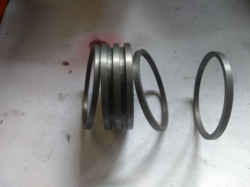
And finally, here we have a piston and three matching piston rings.

If anyone things my maths is a bit dodgy, the word on You Tube is that these get broken easily when tempering or fitting, so I need a spare. In fact I probably need two or 3, but I didn't leave enough metal for this.
I'm really hoping I get my spares tomorrow and can get on with the con rod bits.
Iain
29 May 2019 at 17:40 #411544Samsaranda
Participant@samsarandaI have a variant of the CMD 10 and it does have its limitations, I would think that a 50 mm facemill is probably at the limit or just beyond its capabilities, hence the damage to drive gears. Fortunately I now have a Champion V20 mill for the heavier cuts.
Dave W
29 May 2019 at 20:04 #411568Iain Downs
Participant@iaindowns78295No, No, No, No, Dave!
JasonB has a 50mm face mill on his X3 or something.
I have a 17mm facemill!
I don't aspire to anything that big!
Iain
1 June 2019 at 17:50 #412100Iain Downs
Participant@iaindowns78295Multi-tasking again!
Whilst my armchair engineering has been contemplating budgets and how to cut metal, my active alter-ego has been working on a couple of components.
The cross-head paused whilst the parts to fix the mill turned up. In the meantime I wondered what I could make next. I'd originally bought a piece of 50mm piece of 90mm cast iron bar for the cap. This was as small as I could buy it from Metals4U (I was buying a batch of bits). I was somewhat naive in retrospect for thinking there was any way I could cut a piece of round metal this size in half!
What I realised was that I had a bit of 100mm x 25 cast which I'd bought for some scraping practice – but how much happier it will be to be part of a motor, eh?
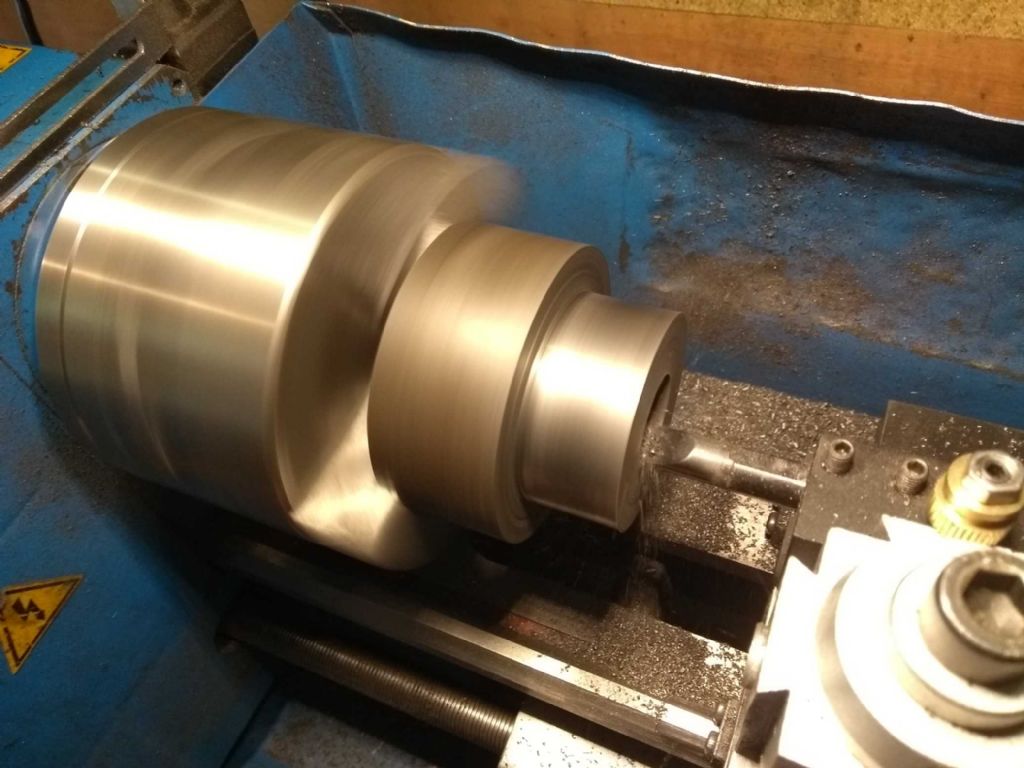
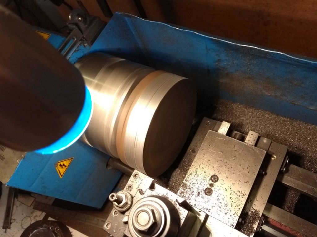
Here it is in my lathe.
I found this difficult to machine and I don't know why. So far cast Iron and I have been quite good friends, but this one didn't like me at all.
I did most of the cutting with an indexed carbide insert and found that I couldn't take more than about 0.25mm off or the lathe would stall. This is not a good thing.
I also had a lot of chatter / squealing so the surface was rougher than I'd like. It was also easy to have a jam and in fact I appear to have chipped (and discarded) at least one of the inserts.
I tried this at speeds from about 300 up to 600 and it didn't make much difference to the chatter.
Still, got there in the end.
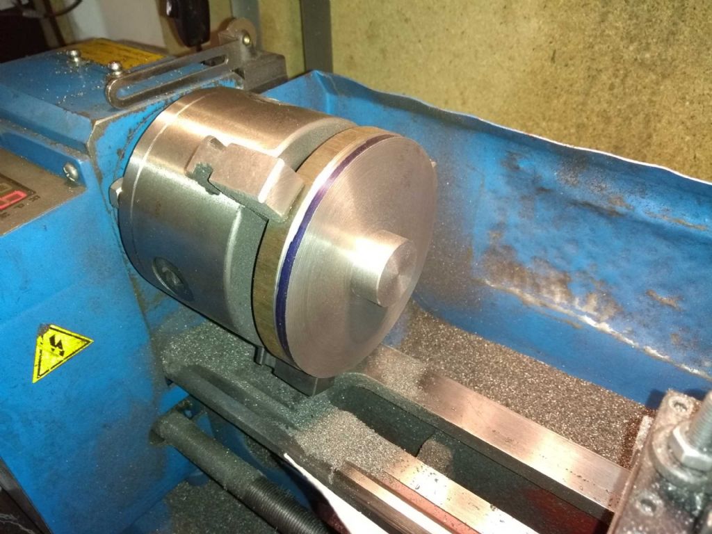
I actually started this because I was trying to be careful (!!!!) with one of my home made tools.
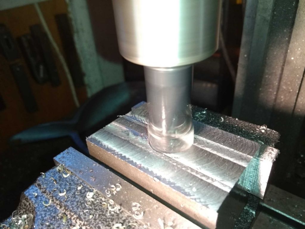
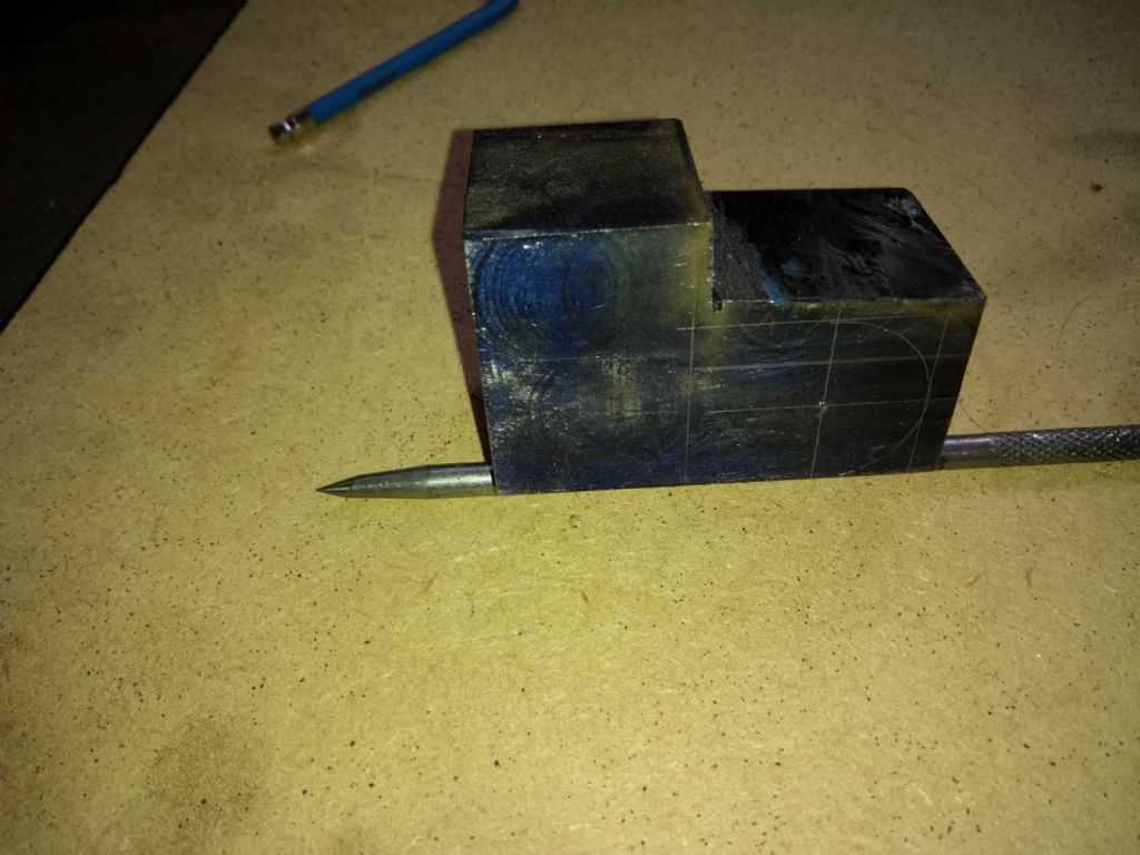
The mill was back in excellent working order so I continued to thin it down to 30mm.
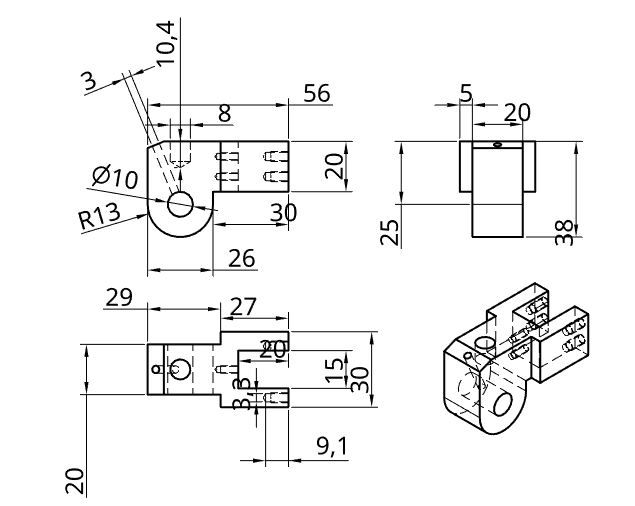
next was to take a corner out – and to clarify this, here is a drawing of the cross head
I thought about setting to with the mill, but it really deserves a break and I thought – Ah- I can saw the bulk of it off and just mill clean!
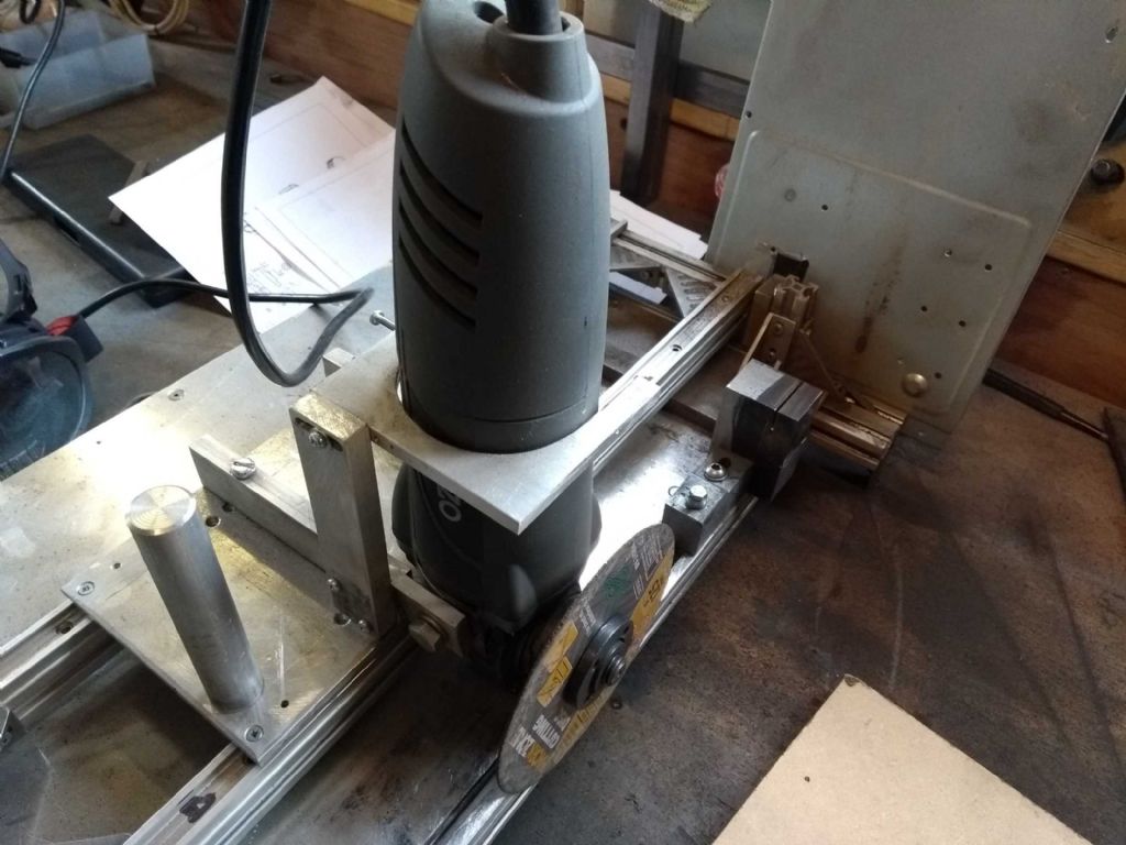
Prior to purchasing my melted chop saw, I'd just finished making a home made version of it. It kind of worked, but not terribly well and I thought my 50 quid was well spent.
So I pulled it out and cut down the excess.
Having (maybe?) learned something about overloading DIY tools with work that's too big, I did this in careful stages, letting the angle grinder cool between cuts. In the meantime I got on with the top cap.
In the end (and with a bit of final help from a human powered hacksaw) I completed the cut and my mill was very pleased indeed!
I shall probably finish this off before getting back to the top cap.
Oh, by the way – Jason you agreed that threading the bottom end of the piston rod was a reasonable approach, but suggested a finer thread. As it happens I have a 10mm 0.5 pitch tap and die set. If I reduce the end to 10mm do you think that would weaken it too much?
Iain
-
AuthorPosts
- Please log in to reply to this topic. Registering is free and easy using the links on the menu at the top of this page.
Latest Replies
Home › Forums › Stationary engines › Topics
-
- Topic
- Voices
- Posts
- Last Post
-
-
road registration and traction trailer.
Started by:
RRMBK in: Traction engines
- 7
- 10
-
6 July 2025 at 22:41
here again
-
Bridgeport ways and wear
Started by:
inline in: Manual machine tools
- 5
- 10
-
6 July 2025 at 22:14
inline
-
Motorised Adept No. 2 Shaper
Started by:
William Ayerst in: Workshop Tools and Tooling
- 9
- 22
-
6 July 2025 at 22:14
William Ayerst
-
Starrett and other tool manufacturer wood boxes
Started by:
Ian Owen NZ in: Workshop Tools and Tooling
- 12
- 16
-
6 July 2025 at 21:43
 Mark Easingwood
-
What Did You Do Today 2025
1
2
…
7
8
Started by:
 JasonB
in: The Tea Room
- 33
- 176
-
6 July 2025 at 21:35
Nigel Graham 2
-
Speed camera
1
2
3
Started by:
 David George 1
in: The Tea Room
- 24
- 61
-
6 July 2025 at 21:05
old mart
-
Pragotron Slave Clock
Started by:
renardiere7 in: Clocks and Scientific Instruments
- 6
- 11
-
6 July 2025 at 21:04
 Robert Atkinson 2
-
Twin Engineering’s heavy mill/drill quill removal
1
2
Started by:
Martin of Wick in: Manual machine tools
- 11
- 29
-
6 July 2025 at 20:30
old mart
-
Herbert B drill – a question and a curiosity…
Started by:
gerry madden in: Manual machine tools
- 2
- 2
-
6 July 2025 at 20:22
bernard towers
-
New member
Started by:
nige1 in: Introduce Yourself – New members start here!
- 4
- 9
-
6 July 2025 at 19:01
 John Hinkley
-
M type top slide conversion??
Started by:
jimmyjaffa in: Beginners questions
- 7
- 14
-
6 July 2025 at 14:20
 David George 1
-
Boiler Design – issue 4765
1
2
…
7
8
Started by:
Charles Lamont in: Model Engineer & Workshop
- 26
- 180
-
6 July 2025 at 13:05
 lezsmith
-
Colchester Chipmaster Clutch question
Started by:
Peter_H in: Manual machine tools
- 4
- 7
-
6 July 2025 at 10:47
Peter_H
-
Sanjay’s Banjo Engine
Started by:
 JasonB
in: Stationary engines
- 3
- 7
-
6 July 2025 at 09:58
 JasonB
-
In memoriam: Peter Neal
Started by:
jamesn in: The Tea Room
- 1
- 1
-
6 July 2025 at 09:53
jamesn
-
Wickseed power hacksaw 8” information
Started by:
simonkeeligan@me.com in: Beginners questions
- 2
- 2
-
6 July 2025 at 07:44
 Nicholas Farr
-
Bentley BR2 Rotary Aero Engine
Started by:
notlobgp14 in: Miscellaneous models
- 4
- 8
-
5 July 2025 at 22:46
notlobgp14
-
Starrett micrometer.
Started by:
Graeme Seed in: Workshop Tools and Tooling
- 7
- 14
-
5 July 2025 at 21:30
 peak4
peak4
-
Dial test indicator vs Dial indicator
Started by:
martian in: Workshop Tools and Tooling
- 17
- 25
-
5 July 2025 at 20:19
martian
-
Any ideas how to repair this?
Started by:
Ian Parkin in: Related Hobbies including Vehicle Restoration
- 11
- 14
-
5 July 2025 at 15:36
Pete Rimmer
-
Chucking Money Away!
Started by:
Chris Crew in: The Tea Room
- 6
- 8
-
5 July 2025 at 12:55
Chris Crew
-
2 Machine lights
Started by:
modeng2000 in: Workshop Tools and Tooling
- 2
- 8
-
5 July 2025 at 11:58
Dalboy
-
Boxford lathe & vertical mill VFD conversion help with start stop
Started by:
Andrew Schofield in: Beginners questions
- 8
- 10
-
5 July 2025 at 11:39
Clive Brown 1
-
1965 Colchester Chipmaster
Started by:
andyplant in: Introduce Yourself – New members start here!
- 6
- 10
-
5 July 2025 at 11:09
Rod Renshaw
-
Amadeal AMABL210E Review – Any Requests?
1
2
Started by:
 JasonB
in: Model Engineer & Workshop
- 16
- 39
-
5 July 2025 at 05:49
Diogenes
-
road registration and traction trailer.
-
Latest Issue
Newsletter Sign-up
Latest Replies
- road registration and traction trailer.
- Bridgeport ways and wear
- Motorised Adept No. 2 Shaper
- Starrett and other tool manufacturer wood boxes
- What Did You Do Today 2025
- Speed camera
- Pragotron Slave Clock
- Twin Engineering’s heavy mill/drill quill removal
- Herbert B drill – a question and a curiosity…
- New member


