Steam Engine Number One

Advert

Steam Engine Number One

Home Forums Stationary engines Steam Engine Number One

Viewing 25 posts - 76 through 100 (of 208 total)
  • Author
    Posts
  • #401324
    JasonB
    Moderator
      @jasonb

      Iain, I would try and add some support to the other end of the cylinder such as an angle plate or even a bit of angle iron would do and should fit if the leg of the "L" faces towards the rotary table.

      You could also rough out a lot of the waste with the cylinder between two angle plates/irons just turning a few degrees at a time and then back onto the R/T for the final rounding cuts which would be a lot more solid. The two 45degree roughing cuts on this cylinder were done like that but you could do say every 10degrees or so just rotating by eye.

      The two angles effectively become the jaws of a vice and if you rest your two flanges on some packing that will set a constant height.

      Also think about getting a roughing cutter and rather than feeding down 1mm at a time use more of the side once you are to depth something like this. The rougher will reduce the load on the machine and you will be using more of the cutting edge rather than just blunt the bottom 1mm.

      Advert
      #402004
      Gas_mantle.
      Participant
        @gas_mantle

        Hi Iain,

        I've been thinking what you said about cutting a large cylinder from solid, this engine on ebay is similar to what I was hoping to achieve from square stock


        Edited By Gas_mantle. on 24/03/2019 18:41:02

        Edited By Gas_mantle. on 24/03/2019 18:46:00

        Edited By Gas_mantle. on 24/03/2019 18:50:29

        #403394
        Iain Downs
        Participant
          @iaindowns78295

          Hi, Gas_Mantle.

          I'm afraid I couldn't work out how the vents channels worked from the picture in that page. I suggest that you need to find (or make) a drawing of what you want to do and ask for advice. I suggest you start a new post which may attract more responses than if it's just embedded in this thread!

          Good luck!

          Iain

          #403399
          Iain Downs
          Participant
            @iaindowns78295

            There've been a few sessions in the workshop since my last post, but I've not had a chance to post them up.

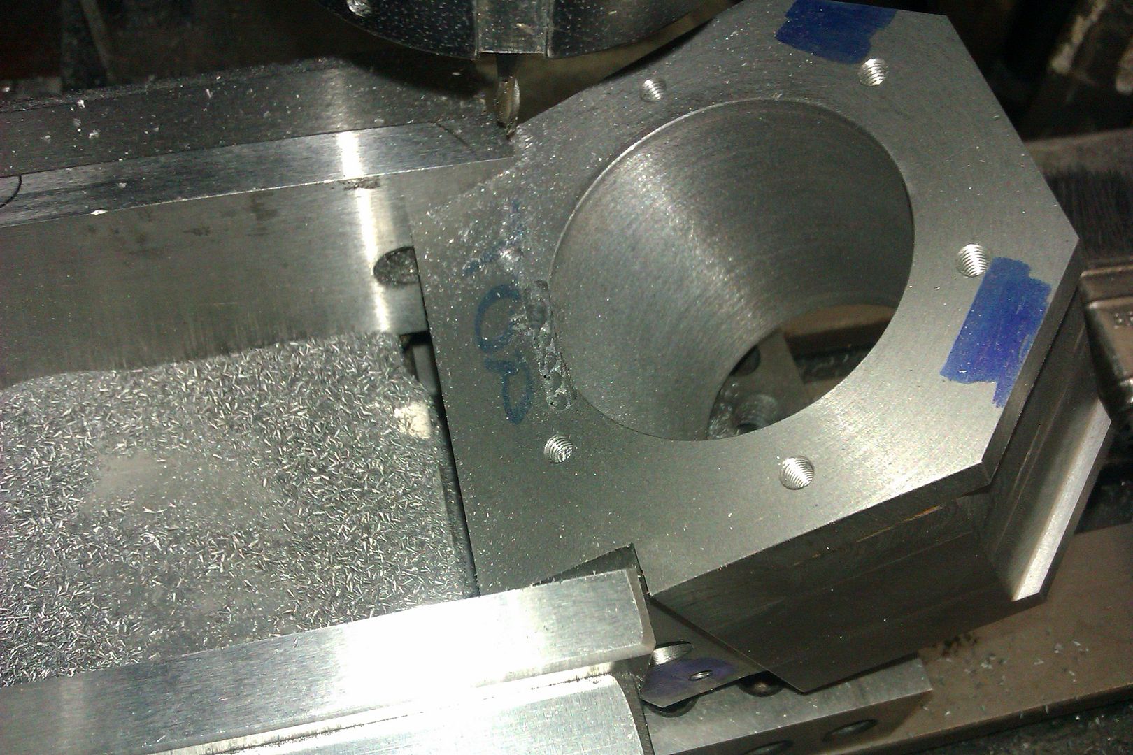
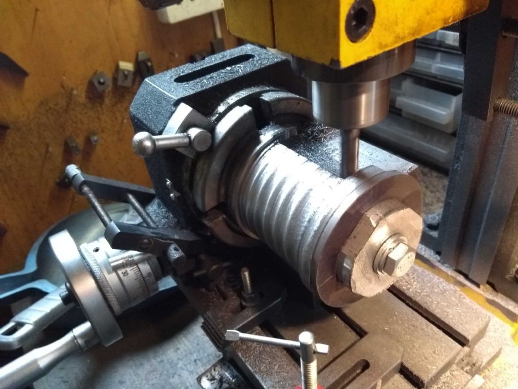
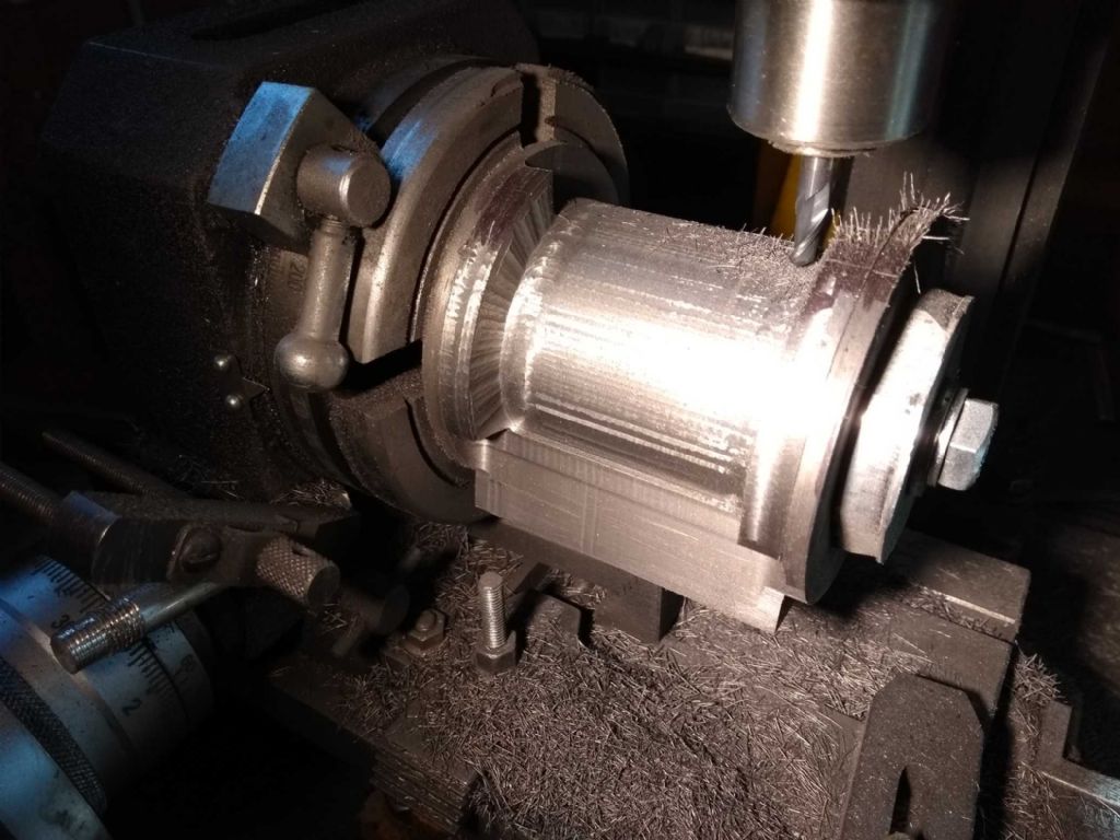
            I found I'd gone a bit too far to follow some of Jason's advice. I already had a cylinder of sorts so roughing out at 45 degrees didn't seem like it was worthwhile. However, the idea of taking a deeper cut to use more of the mill struck me as eminently sensible.

            cylinder deep cut.jpg

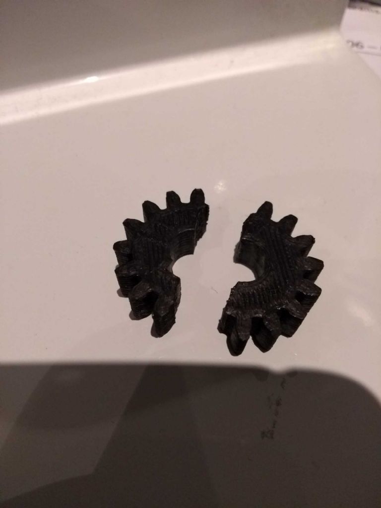
            Despite this being sensible, it proved a little too much for the poor mill – to be more accurate my 3D printer! IN an earlier episode, the motor drive gear had give up the ghost and I'd replaced it with a 3D printed one, which has supported my endeavours tidily through the past few months. However, this was too much for it.

            cylinder broke mill.jpg

            Poor thing. I did attempt to superglue it back together, but this lasted but moments. As the shattering of the gear resulted in the key (conductive) ricocheting round the box which contained the motor controller (electric!) I decided that prudence was the order of the day and reached out to ARC for spares.

            Why not print another one you ask? Well I didn't but it was not a good print. I think my printer needs some maintenance – I find them temperamental things.

            Usual excellent service from ARC and a couple of days later I had the cogs, but other things got in the way and I only returned to the task today.

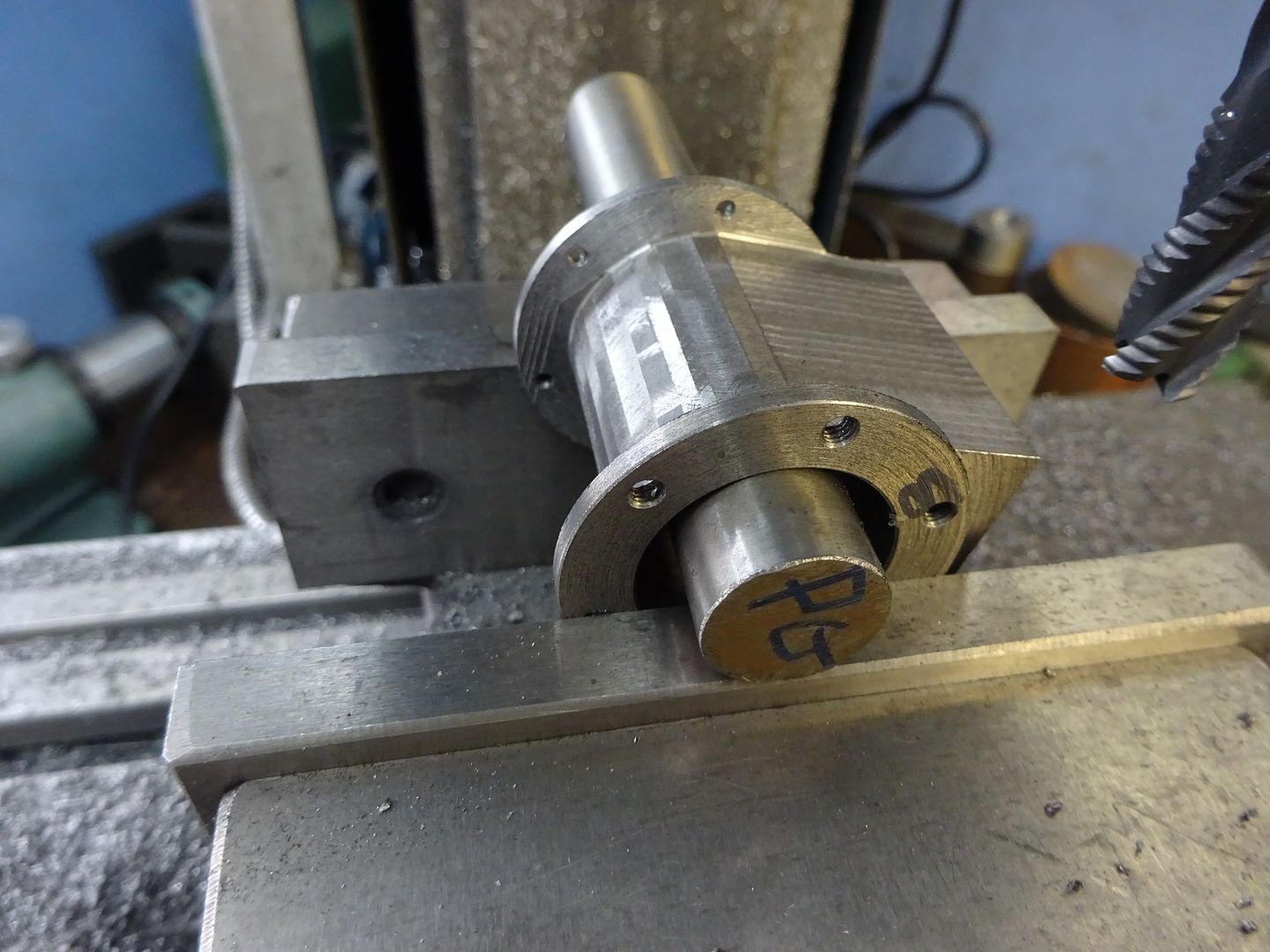
            Because I had to leave some metal for drain taps, I'd decided to carve out the cylinder 8mm short of the end flanges and then separately carve out the remaining 8mm (apart from the tap mounts) with a snub ended mill. I'm told that one should try and avoid sharp edges! My first snub nose use…

            cylinder cut around spigot.jpg

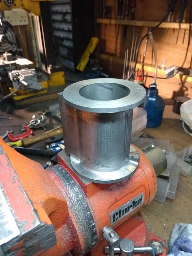
            And finally, the finished product!

            cylinder done bar ports.jpg

            To finish this off, I need to mill out the valve ports, lap the valve face and drill the end cap mounting holes.

            I might leave that for a while and get started on the big connecting rod assembly. Which means back to the drawing board as I need to finish of some changes.

            In a spirit of masochism (for a Yorkshireman), I weighted the part. A tad over 1Kg. which means I've flushed away 90% of the cast iron I paid for! That hurts…

            Iain

            .

            #408594
            Iain Downs
            Participant
              @iaindowns78295

              To those of my devoted followers who have been wondering what I've been doing for the lat month, the answer is, 'not a lot'. Not of taking perfectly good metal away from a part.

              Most of that is professional domestic, however, I have been a bit stuck on the cross head guide for my engine. If you recall I had not realised that such was necessary so hadn't considered it. Geoff walker and Jason B help me to understand about the tubey type of guide and of course I think I'd already seen the squarer, slidey type of guide (most used in horizontals).

              This seemed complicated so I got on with making the bits I did understand (more or less!). Now, however, I'm at the point of making the con rod assembly so it's become important.

              The thing that I'm trying to work out is which is the easiest to fabricate with the least precision required.

              The slidey type guide I think would be easiest in a horizontal, but with an open column engine (I think it's called) I would struggle to find somewhere to put it and it spoils my artistic idea of tapering the columns. It's a lot of pieces (or a lot of machining), but I guess it could be done.

              The tubey type thing actually looks more doable, though there's an uncomfortable amount of accurate concentric lathing to do. It is also probably more aesthetic given the type of engine.

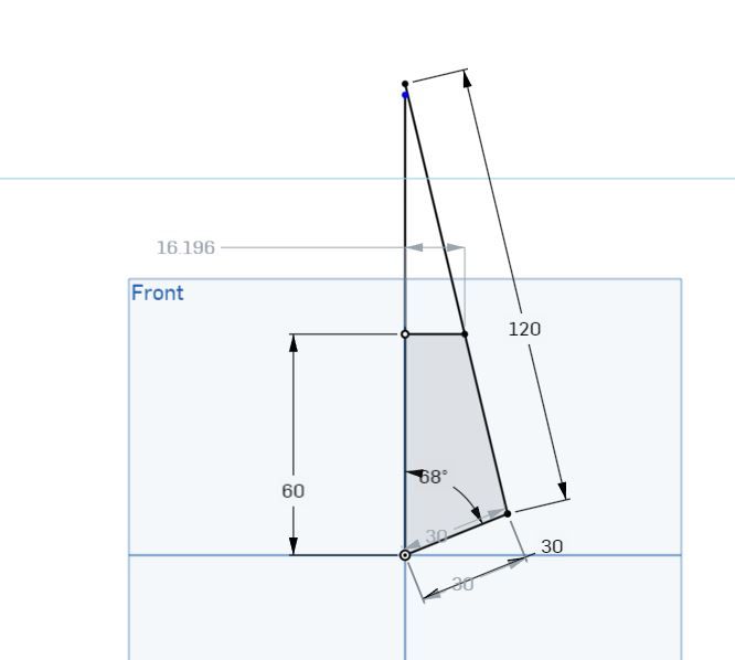
              With a stroke of 60mm I have a throw of 30mm. The big end rod is designed at 120mm (2 * stroke). According to my excel calculations (checked roughly in my CAD package), that means that the maximum excursion at the bottom of where the tube needs to be is about 16 mm (at a bit over 65 degrees from TDC).

              Add half the diameter of the con rod (13mm dia) and the internal bore of the tubey thing needs to be 32+13 = 45mm.crossheadsizing.jpg

              So I'd need a tubey thing with an internal bore of 45 – 50mm.

              One of the reasons for going into this dull detail is that Mr Ballamy suggested that a tubey thing (page one of this epic) with an external diameter of 25mm and an internal of 18mm would be a good start. I expect this was just a wild arsed guess, but I tend to treat his wild arsed guesses with a bit more seriousness than my careful plans, so wanted a sanity check.

              Ray Hasbrouk's Engine number one has been one of my inspirations and that has a tubey thing made from 2 inch iron pipe which sounds close to my calculations. I don't know where to get 2 inch pipe (in 6 inch lengths!) and have an aversion to buying 50mm round bar and taking away 90% of it.

              So I throw myself on the mercy of the expertise. Is buying a bit of rod and exercising my best boring bar the best way or should I try and rethink the design – perhaps even go for a slidey thing.

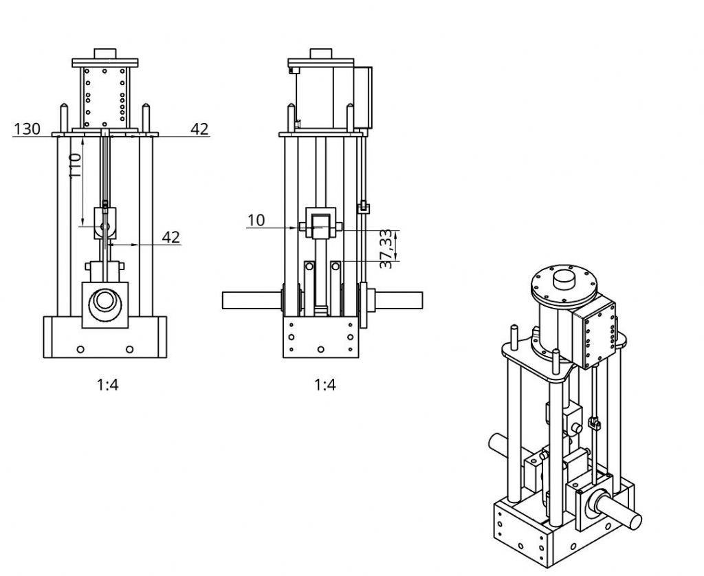
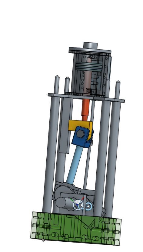
              For what it's worth, this is the outline of the engine design as it stands at the moment, without adding crosshead support.

              engine3.jpg

              Any advice provided today will allow me to buy parts in Doncaster tomorrow. No pressure .

              Oh – and one attempt at the big end bearing went badly wrong as I tried to mill it to width. Something slipped and one side ended up 5mm lower than the other – and too low. So I've re-ordered a bit of cast and reduced it with the lathe which has worked better. I'm hoping to get close to finishing that today.

              As usual, my thanks in advance.

              Iain

              #408620
              JasonB
              Moderator
                @jasonb

                yes my 1" guide wa sa bit small given the size of your engine. I have just looked at my Todman which is 76mm stroke, 140mm conrod and has 41.25mm between the guides. based on that you should be able to get something around the 38-40mm internal diameter.

                Did a rough sketch of your engine frame, scaled my conrod and crank down to your sizes and sketched out a quick trunk guide (tube thing) with a 40mm bore, 4mm wall.

                If you stick with a parallel 13mm rod you will need the small 1mm x 2mm chamfer for clearance but if you belly the rod as shown then you could omit the chamfer. Or keep the chamfer and reduce bore to 38mm. Cross head will just pop out the bottom of the guide but that will save wearing any ridges.

                 
                Just so happens that a bit of scaffold pole will come up just over 40mm after the inside has been skimmed and leave approx a 4mm wall. So you could either silver solder that to a disc and then skim the flange it forms and the bore in one setting so it is all true or cut from 50mm or 2" square bar which allows enough for M5 nuts in each corner to fix the flange with.

                Edited By JasonB on 10/05/2019 14:47:40

                #408812
                Iain Downs
                Participant
                  @iaindowns78295

                  Thanks for the useful (as always) advice.

                  I was heading towards buying some 2 inch bar at the show today, but on the way round I saw a part finished engine which used a rod as a cross head guide. This looked like it was half again or twice the size of mine and probably for a steam engine.

                  What was interesting was that the cross head ran along a rod which inspired me to think of trying that design. The main attraction is a somewhat simplified construction.

                  Here is the basic idea

                  crossheadguiderod.jpg

                  The rod would obviously be better secured and could even be secured against the pillars. The rod (or is that bar?) would be steel and I'd use a bit of bronze on the front and back as a bearing material. Obviously that aspect's not in the image, but I wanted to get the idea across.

                  This seems like it should be easy to do and a bit of shim here and there would allow for adjustment.

                  Also bought was an inch of 6 inch round for the flywheel, a new machine vice (may end up being too big) and (cheating really) the drain cocks from Polly.

                  Any comments more than welcome.

                  Iain

                  #408880
                  JasonB
                  Moderator
                    @jasonb

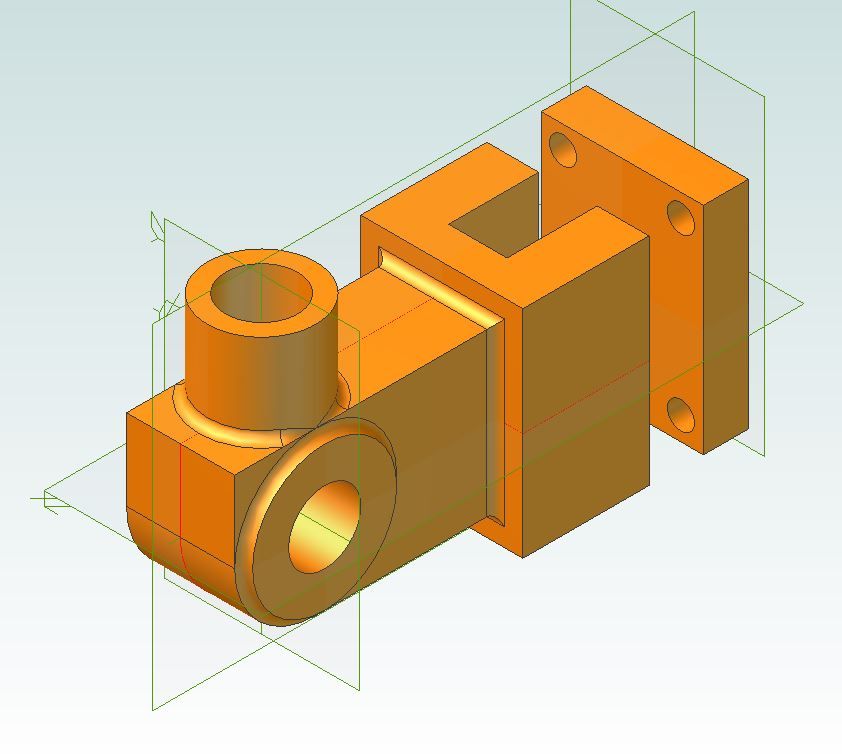
                    Ideally the crosshead would be forked to fit around the sides of teh guide bar and then a plate screwed across the open end of the fork to retain it on the bar. That way you have some sideways guidance and could run the engine in either direction as the cross head will want to pull away from the guide when run one way and against it the other. This sort of thing but a bit simplified

                    crosshead.jpg

                    The bottom of teh guide should be retained but that would be easy enough to do by milling flats on a couple of teh cloumns to allow a cross piece to be fitted and the guide fixed to that.

                    Edited By JasonB on 12/05/2019 07:43:29

                    #408884
                    Gas_mantle.
                    Participant
                      @gas_mantle

                      Good to see you back at it Iain, I'm still following along with interest.

                      Jason just as a matter of interest what is that engine in your last photo?

                      #408885
                      JasonB
                      Moderator
                        @jasonb

                        2" scale BB1 ploughing engine (not mine)

                        #408887
                        Gas_mantle.
                        Participant
                          @gas_mantle
                          Posted by JasonB on 12/05/2019 08:04:12:

                          2" scale BB1 ploughing engine (not mine)

                          Looks to be a nice engine

                          #408893
                          Iain Downs
                          Participant
                            @iaindowns78295

                            Thanks, Jason.

                            I did have in mind to do the fork thing. It just takes me a (relatively) long time to draw things up in OnShape (inexperience more than anything else – the tool is pretty good, probably to sophisticated for me).

                            I was actually going to bolt some bearing bronze to the cross head on the inside and the outside so that I can could adjust the fit with shims or something – either when the bearing wears or when my fitting turns out to be just a tad rubbish.

                            I need to think a bit about the bottom support. The plan was to screw the pillars into some blind M8 holes. The threaded holes are already in place and blind to avoid the bolts that hold the crankcase together.

                            I guess I can find smaller bolts and drill through at 8mm. Or make a mount that clamps to the pillars.

                            Cheers.

                            Iain

                            #408974
                            Iain Downs
                            Participant
                              @iaindowns78295

                              I'm going to blame my tools. Yes I know what they say.

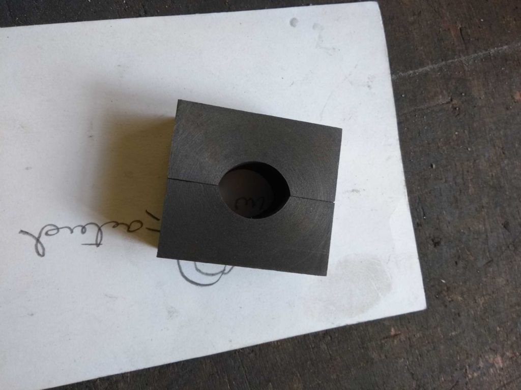
                              Yesterday I trimmed my bit of cast for the big end bearing and slit it down the middle (and glued it back together). Today was the day to bore it out.

                              And I cocked it up. The bore is now 20.35 mm for a crank journal of 20.00. As Mr Micawber might say, 'result, misery'.

                              Apart from my general cack-handedness, I can trace this particular error to my new (cheap) digital calipers from Aldi. I'd stopped using my old well used (cheap) calipers, because the new ones didn't turn off after 5 milliseconds and if they did turn off, they remembered the position. This makes it just a little easier to use.

                              Unfortunately, they lack in the accuracy department. I'd bored the hole out to 19.97 mm or so (proud of myself!) and test fitted a bit of the 20mm silver steel – only to find it rattling something rotten. Checked with my old reliable (but turning off) caliper and got 20.35 – which explains the rattle.

                              Mr Aldi's caliper has been consigned to file 13 and I will now buy another inch of cast and go through the process for the third time of asking. Sigh.

                              And worse, I no longer have even the most tenuous excuse for not painting the fence.

                              Damn.

                              Iain

                              #408975
                              JasonB
                              Moderator
                                @jasonb

                                is the outside to finished size? if not take the halves apart, skim the mating face and stick back together for another go

                                #409108
                                Iain Downs
                                Participant
                                  @iaindowns78295

                                  Saved by the Ballamy! (sorry).

                                  The width is to finished size. The height is not. My drawings are far a bearing wall thickness of 5mm, but that has come to feel to small, so I then thought about 8mm. As I've not decided I've left top and bottom over 10mm and planned to ask the audience what was sensible later (which turns out to be now).

                                  A few moments with OnShape showed me that I needed to remove about 2.3mm off each face, so I took off 2.5mm.

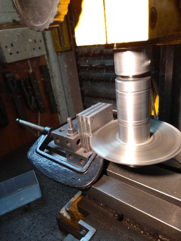
                                  That went quite well with my new vice and a 17mm face mill,

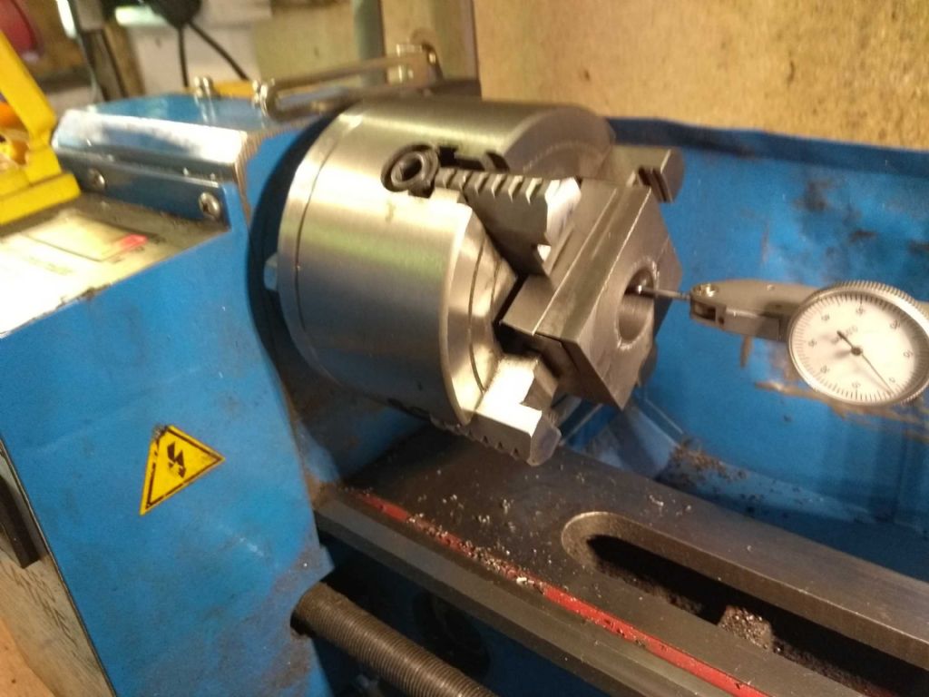
                                  The thing that made me nervous about Jason's approach was how to centre it in the four jaw. In the best of circumstances this takes me 20 minutes – with an add shaped hole?

                                  It occurred to me that I could recenter the bore the hard way – that is by trimming the sides down until the bore was central and so I too the lazy way out. I pushed the bearing up against chuck face with a centre in the tailstock and adjusted by eye.

                                  Seems to have worked out, though I was clearly a bit over on one side as there is a small groove where the two halves meet.

                                  In other news, I did paint the fence – at least until the paint ran out. Sadly, there is another pot in the shed (taking up perfectly good tool space) so I will have to get back on that soon.

                                  And I got a job offer! So I will have to hurry up and get the hard bits of the engine out of the way before I'm back in full time work…

                                  Off to chill the champers and light the BBQ.

                                  (Pictures in a later post)

                                  Iain

                                  #409274
                                  Iain Downs
                                  Participant
                                    @iaindowns78295

                                    I promised pictures. This one has been a B**CH (Language moderated due to innocent bystanders…).

                                    I started off with good intentions and a nice bit of cast.

                                    bigend bearing raw 1.jpg

                                    The plan conveniently in the photo.

                                    The first thing I did wrong was to trim too much off. I was using the mill to reduce the height by 5mm or so. (1 inch to 20mm). I was taking about 3 mm deep cuts but .5 – 1mm deep if that makes sense. I was (or thought I was) keeping an eye (and a hand) on the Z axis dial mainly as the poor mill was juddering a bit and the dial tended to drift. Despite this it some how cut 4mm deeper at the back than the front.

                                    This one was definitely 'bad workman'! I decided that this wasn't going to work, so reserved if for practice (for the valve face) and bought another bit.

                                    This time I took it down near size on the lathe which worked better. Sliced it in two with a slitting saw as below.

                                    bigend bearing splitting.jpg

                                    That went quite well, though I ended up changing the clamping mechanism as the clamps stuck out to much into the barrel of the saw.

                                    Happy, happy!

                                    Then on to drilling out and boring.

                                    bigend bearing boring.jpg

                                    That seemed to go OK, but I managed to cut it 0.4mm over (see early post passing responsibility off onto my tools!).

                                    All seemed lost until the kind Mr. Ballamy suggested I split, thin and retry.

                                    bigend bearing thinned.jpg

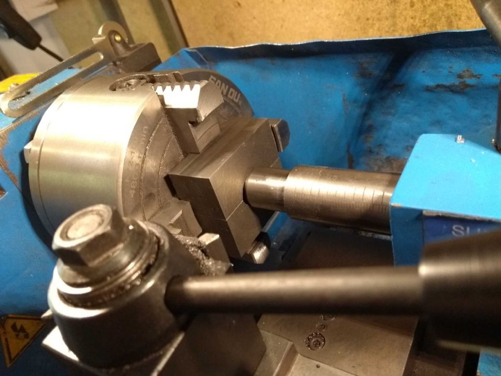
                                    The thing I was worried about was centering, but in the end I just used the centre from the tailpost as here.

                                    bigend bearing recentering.jpg

                                    And added the sticky up bit (sorry, I don't know the correct engineering term – but this…)

                                    bigend bearing rescued side 1.jpg

                                    Then my troubles really began!

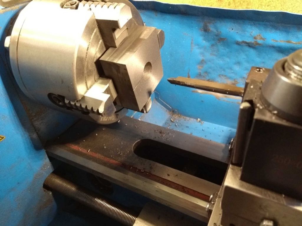
                                    I found it (nearly) impossible to mount the block in the 4 jaw and get it centred. In confession, I am TERRIBLE at centring in the 4 jaw. I seem to get the rough adjustment with the chalk circle OK, but then it all goes to pot with the clock and I have to go back to the chalk circle again.

                                    bigend bearing side 2.jpg

                                    In this case matters were made worse as the block was getting gouges in where I tightened up too much. This made adjustments in the other access difficult, with the jaws dug in. I tried some hard shims, but I was getting nowhere (about 2 hours of nowhere by now!). Then I noticed that when I tightened the jaws (I mean reasonably firm not tight tight), the block was moving- moving away from the chuck face.

                                    So each time I moved it to correct a clocking error it was adding another error due to the movement. I have no idea why this is except perhaps it was a fairly low hold with an 'amateurs' vice.

                                    I gave up.

                                    I then had the marvellous idea of trying to hold the 2mm stub in the 3 jaw (the bit I don't know the name for). I thought this probably wouldn't work and I was right. the minute the tool touched the surface, 'Spung!', it jumped off the chuck.

                                    I thought of mounting it on the faceplate or making a stub mandrill, but all of those required quite a bit of work (I have no suitable clamps for the faceplate, though a mandrill could have been possible.

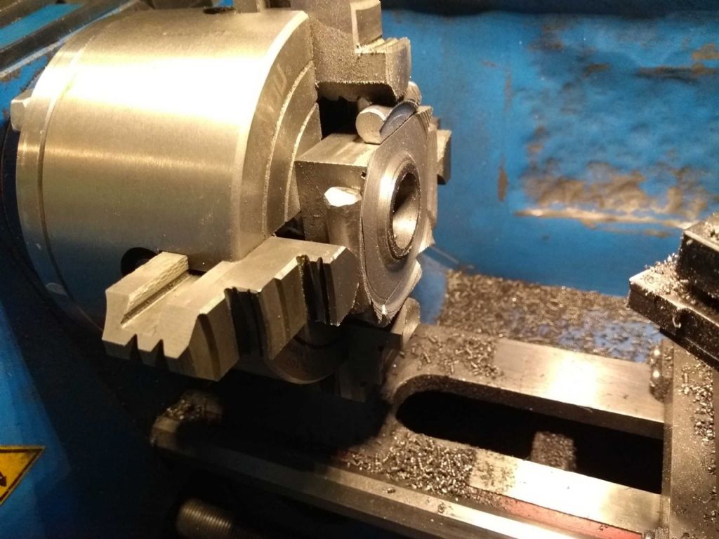
                                    On the verge of packing in for the day and going to take consolation with my friend Vin (Vin Rouge that is), I thought of turning the 4 jaw chucks jaws round to give me a higher grip.

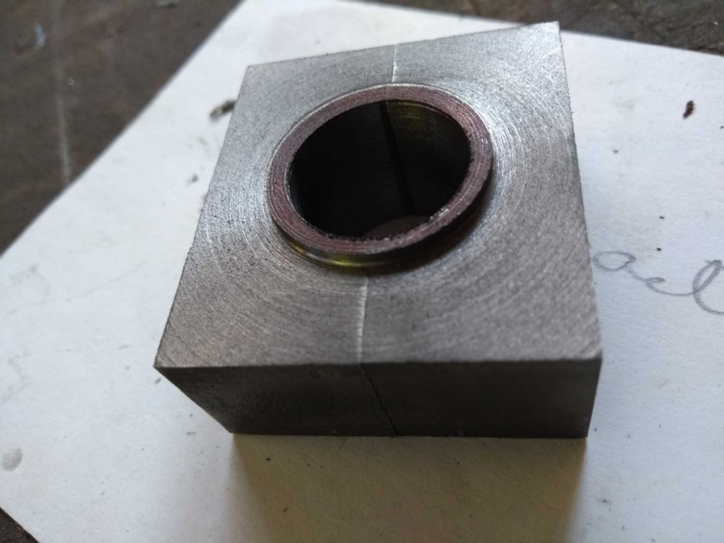
                                    This worked better than I deserved as it turns out the centre hole in the chuck is almost exactly the diameter of my sticky out bit!

                                    bigend bearing side 2 finally.jpg

                                    The jaw height closely matched the bearing height so I needed add some separators to give me space to get in and cut. Even then I struggled to get the tool in and couldn't cut to the edges.

                                    I tool cuts to get to the right depth with the (carbide) tool at an angle and then straightened it out to make the outside of the sticky out but vertical.

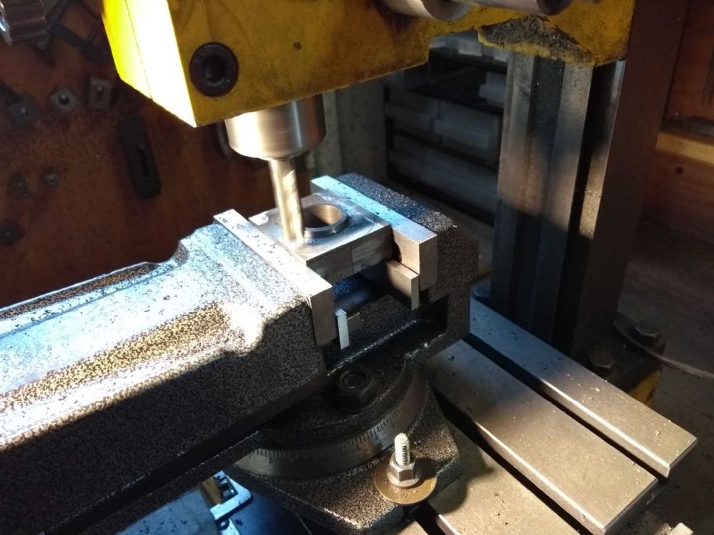
                                    Finally, I took it to the mill and smoothed off the corners that were sticking up.

                                    bigend bearing finally trimmed.jpg

                                    Final step with this damned thing is to trim it..

                                    Iain

                                    #409293
                                    Blue Heeler
                                    Participant
                                      @blueheeler

                                      Thoroughly enjoyed this thread, looking forward to your next installment.

                                      #409521
                                      Iain Downs
                                      Participant
                                        @iaindowns78295

                                        I suck at soldering.

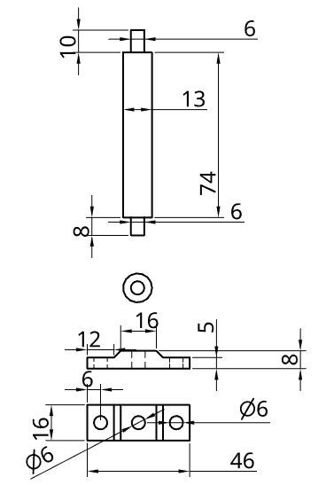
                                        I wanted to do some practicing before I messed up some precision (!!!) crafted pieces of the con rod assembly.

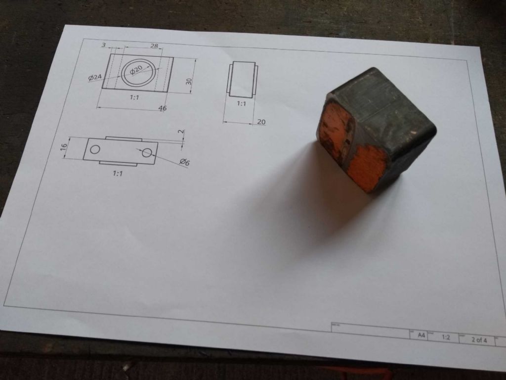
                                        So I turned a rod to match the con rod and made a piece the same size as the big end bearing connector.

                                        lower con rod.jpg

                                        But I cannot make the soldering work.

                                        I have some insulating breeze blocks (I forget the type, but the ones recommend in this forum) for my hearth. Having been told that my B&Q torch wouldn't touch anything much bigger than a ring, I bought a Sievert torch kit (with a 2941 burner – 7.7kW apparently).

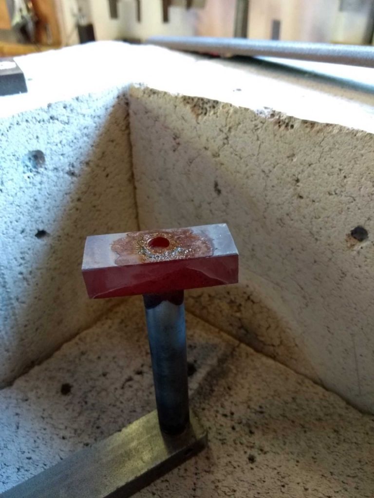
                                        This is the part after an unsuccessful attempt to solder

                                        conrod soldering practice.jpg

                                        I'm using 455 solder which has a relatively low melting point and I think that despite the investment in the torch I can't get it hot enough quickly enough. Even spending 5 – 10 minutes heating it up, it's still not hot enough to melt the solder when the solder is touched to the red hot metal.

                                        I first tried it with the parts in a 'normal' orientation (rectangular bit down on the bricks) and then as you see here.

                                        I don't know if I'm not adjusting the torch correctly. The flame isn't quite the neat cone I would expect – though it seems a bit erratic – perhaps something needs tightening or cleaning (but not today).

                                        I suppose I want to check that I should be able to solder a piece of this size with the equipment I've got. If not then I need to rethink the design (super glue and pins?).

                                        In useful work, I started on the big end bearing connector. Now trimmed to height and width.

                                        Iain

                                        #409522
                                        JasonB
                                        Moderator
                                          @jasonb

                                          Should not be a problem with that torch/burner combination.

                                          What flux did you use?

                                          What regulator have you got on the bottle and what have you set it at?

                                          Edited By JasonB on 16/05/2019 17:21:56

                                          #409546
                                          Iain Downs
                                          Participant
                                            @iaindowns78295

                                            I used the flux that CuP provided with the solder and torch.

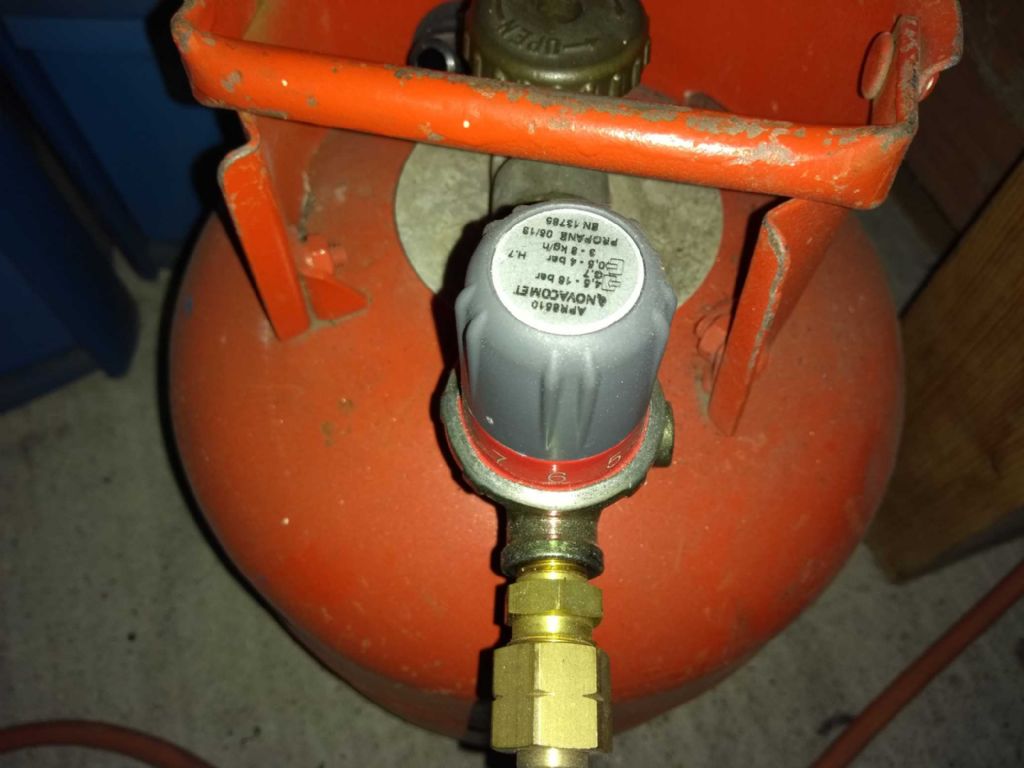
                                            This is the regulator.

                                            gas regulator.jpg

                                            It's set to 5 – at least the number pointing to me is 5.

                                            Many thanks

                                            Iain

                                            #409577
                                            JasonB
                                            Moderator
                                              @jasonb

                                              Did you get one of their starter packs? if so it was more than likely their "EF" pack", you would have done better with the HT pack or some HT-1 flux as this will be better for any jobs that take longer to heat.

                                              Looks like a high pressure regulator so should have been giving a reasonable amount of heat at the mid setting, try it on the max to see if your torch burns more, it may not as the jet in the torch will be the limiting factor.

                                              #409582
                                              Michael Gilligan
                                              Participant
                                                @michaelgilligan61133
                                                Posted by Iain Downs on 16/05/2019 20:48:42:

                                                It's set to 5 – at least the number pointing to me is 5.

                                                .

                                                This appears to be the same regulator: **LINK**

                                                https://www.bes.co.uk/propane-high-pressure-regulator-050-to-4-bar-9308

                                                But I can't see the pointer on yours dont know

                                                MichaelG.

                                                Edited By Michael Gilligan on 17/05/2019 07:41:31

                                                #409583
                                                JasonB
                                                Moderator
                                                  @jasonb

                                                  Well found Michael, if Iain's one is anything like the link then the pointer is at the bottom of the label so pointing to 0 or 1 which would be a bit low!

                                                  #409777
                                                  Iain Downs
                                                  Participant
                                                    @iaindowns78295

                                                    Who would have thought it?

                                                    You have to turn the gas ON to get a soldering torch to work! Well, well – you learn something new everyday.

                                                    I do feel like a bit of a plonker to be honest, But I am truly grateful for my muses who have helped out and managed it without pointing out that I'm an idiot (I wouldn't have managed!).

                                                    Today, I practised soldering. I would like to say that this went swimmingly well, but it did not. Yes I am getting more heat and my first go I got solder to seep through one side of the hole (but not the other). The second go got really hot and the solder melted but didn't seep. I suspect in both cases that the parts already having been used for a test meant that there was too much scale or something.

                                                    I will make new parts tomorrow and have another go.

                                                    I also trimmed down the big end bearing so that the height is right and completed the sizing of the bearing connector. Tomorrow (as well as soldering practice) I will drill and ream the bearing and holder. Shortly after that I will need to develop soldering skills .

                                                    Iain

                                                    #409797
                                                    Michael Gilligan
                                                    Participant
                                                      @michaelgilligan61133

                                                      Well done, Iain … keep at it yes

                                                      MichaelG.

                                                    Viewing 25 posts - 76 through 100 (of 208 total)
                                                    • Please log in to reply to this topic. Registering is free and easy using the links on the menu at the top of this page.

                                                    Advert

                                                    Latest Replies

                                                    Home Forums Stationary engines Topics

                                                    Viewing 25 topics - 1 through 25 (of 25 total)
                                                    Viewing 25 topics - 1 through 25 (of 25 total)

                                                    View full reply list.

                                                    Advert

                                                    Newsletter Sign-up