Steam Engine Number One
Steam Engine Number One
Home › Forums › Stationary engines › Steam Engine Number One
- This topic has 207 replies, 23 voices, and was last updated 7 February 2022 at 12:58 by
 Andy_G.
-
AuthorPosts
-
13 December 2018 at 17:39 #385499
Iain Downs
Participant@iaindowns78295Hmm.
So would this be a sleeve (like f:0″>this one on eBay)
I would get one with a 22mm inner bore and just slip it in the bearing blocks? Or do I split it somehow? Do I need to lap it in?
How would I retain it? would I need to machine a grove? Do I need to put an oil groove inside it?
Aluminium is appealing. So much easier to work with.
And a million other questions.
I presume I would still need to make a split bearing for the big end and eccentric…
Iain
13 December 2018 at 19:02 #385506 JasonBModerator@jasonb
I have used the Oilite type bearings on a couple of hit & miss engines where their use is specified and it works out as a quick and easy way to do it. They are really designed to be pressed into a hole which compresses the bush slightly so are a fraction oversize as supplied but only a thou or so, Can't see why you could not split them although the resulting gap left by the saw cut may break down the oil film.
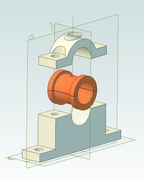
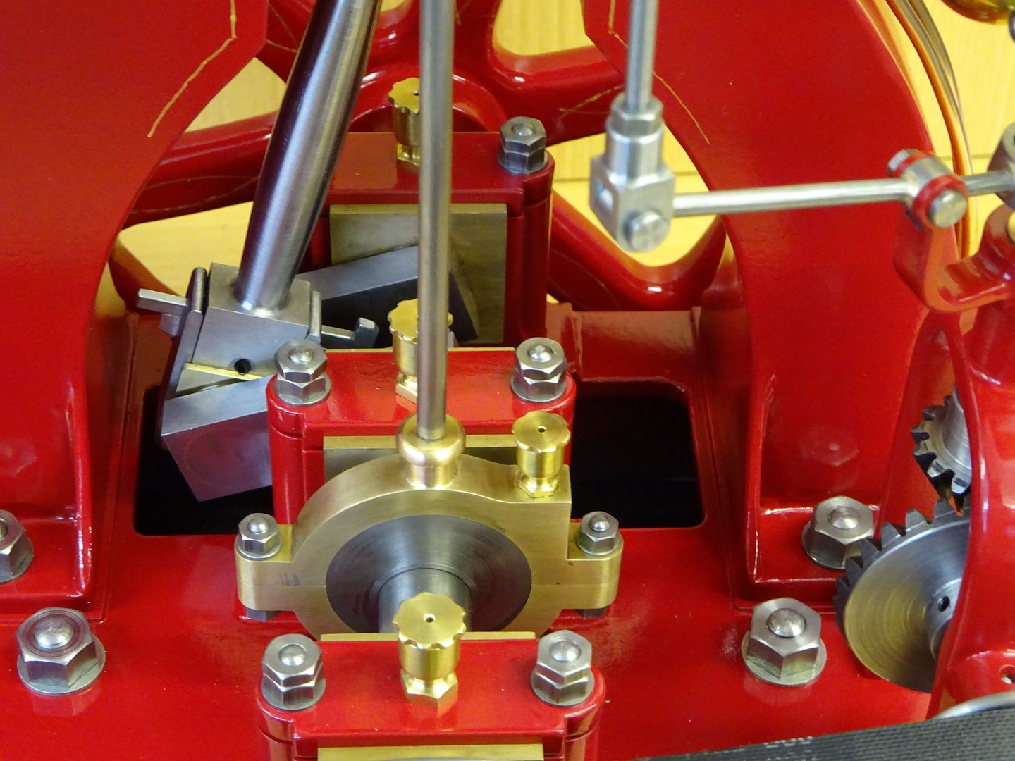
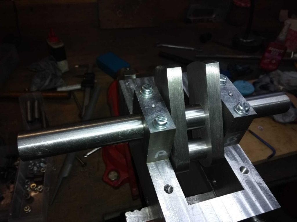
If you do go down that route then you can get them with a flange on one side, if this were placed on the inside edge the crankshaft webs can butt upto the flange and that will stop the bush moving sideways, a bit like this

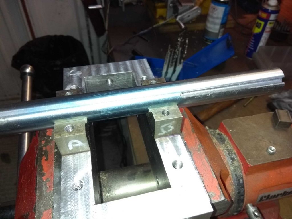
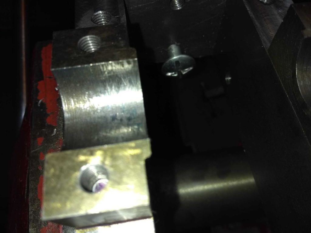
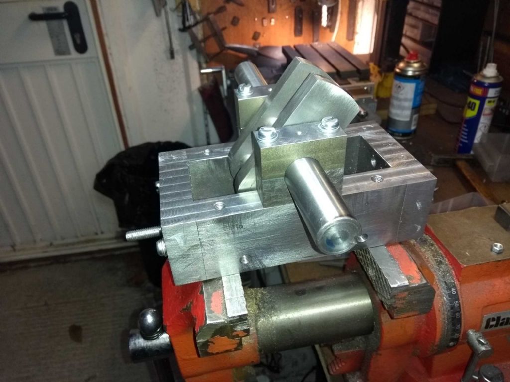
The other option is to solder two blocks of bronze together then machine them to fit your shaft and reduce the middle section so you have a flange at each end, could even glue some CI together as it's a bit cheaper than bronze. Something along these lines would work for you.
If you don't fancy round then square/rectangular work too


Yes you will need to split the big end to get it onto the crank, depending on eccentric design you can get away without splitting the strap but on the size of engine you are making I would split it.
13 December 2018 at 19:39 #385514Mikelkie
Participant@mikelkieI cast aluminium plummer block type of bearing supports for a cropping machine i built about 2 years ago with a shaft od of 30 mm. the aluminium was automotive cylinder heads from scrap dealers. the final reamed holes left a shiny finish and is a exellent bearing material. I will try and use alli casting wherever possible,and currently making horn blocks for a 7 1/4 loco from aluminium too
18 December 2018 at 07:23 #386207Iain Downs
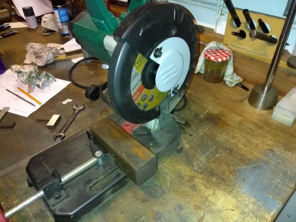
Participant@iaindowns78295I got my real cast iron block yesterday and spent an hour cutting and squaring
I do like my Aldi cut-off saw! A precision instrument it is not, but it gets through big lumps of metal in no time. I'm working out how to use it to saw a bit of a 100mm cast iron round bar, which will need different clamping somehow.
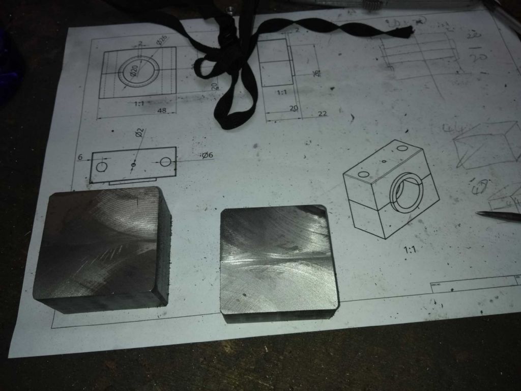
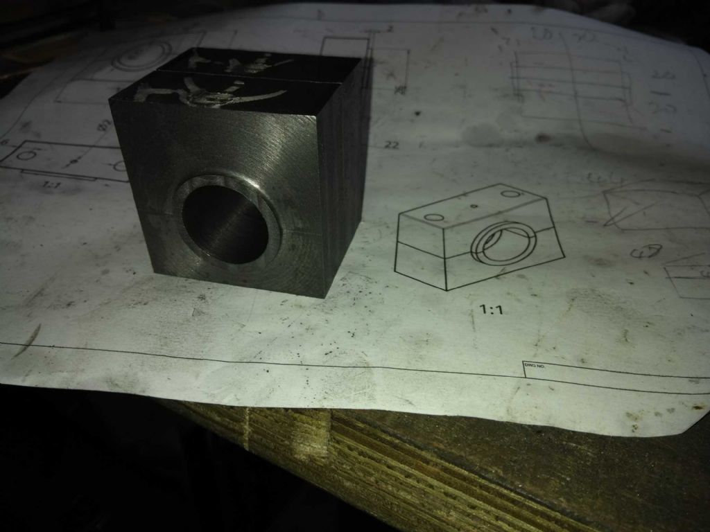
The plan is to square up and, from a face end cut it 20mm up, then glue back together then cut 22mm out and re=glue. Finally trim the rest to size so I have two bearings hidden in the iron and bore out and finish.
May finish squaring and do some cutting tonight if all goes well.
Iain
27 December 2018 at 16:01 #387830Iain Downs
Participant@iaindowns78295So 10 days on and a mix of results to report.
As stated the plan was to slit the iron into 4, bore and break apart. Here's how far I've got.
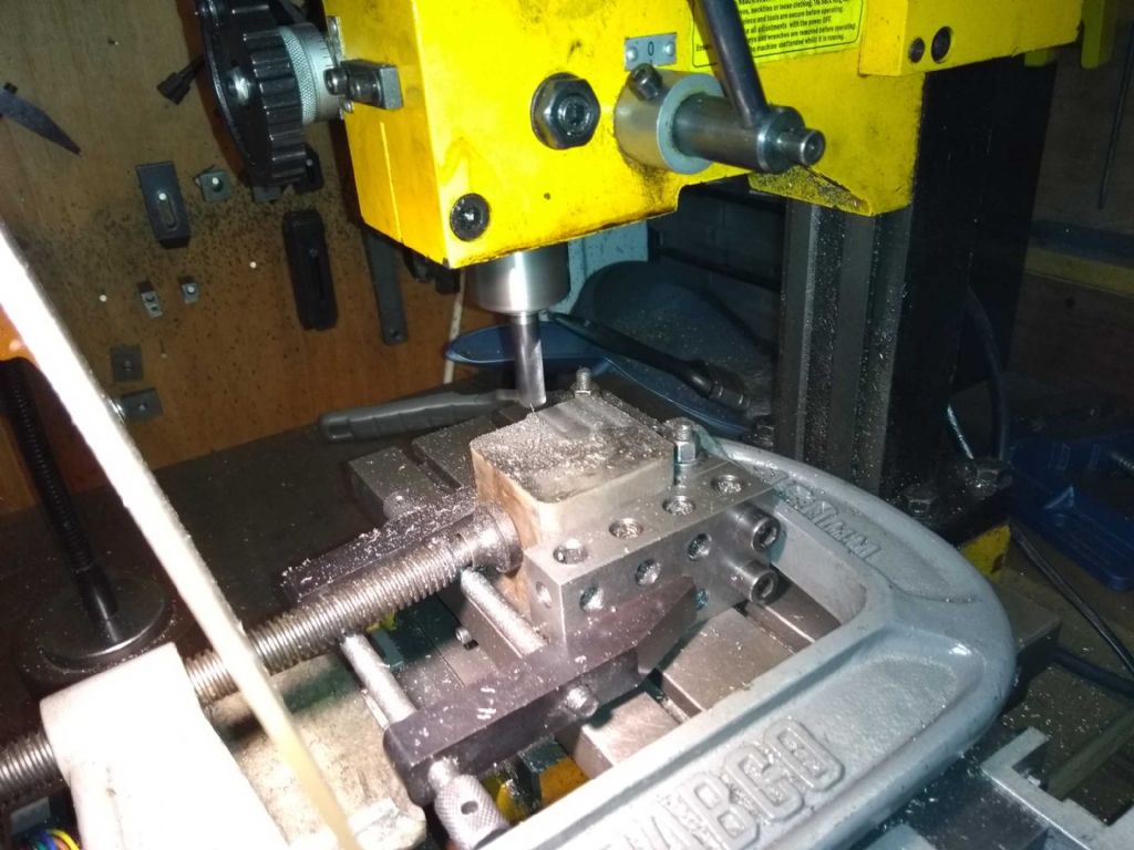
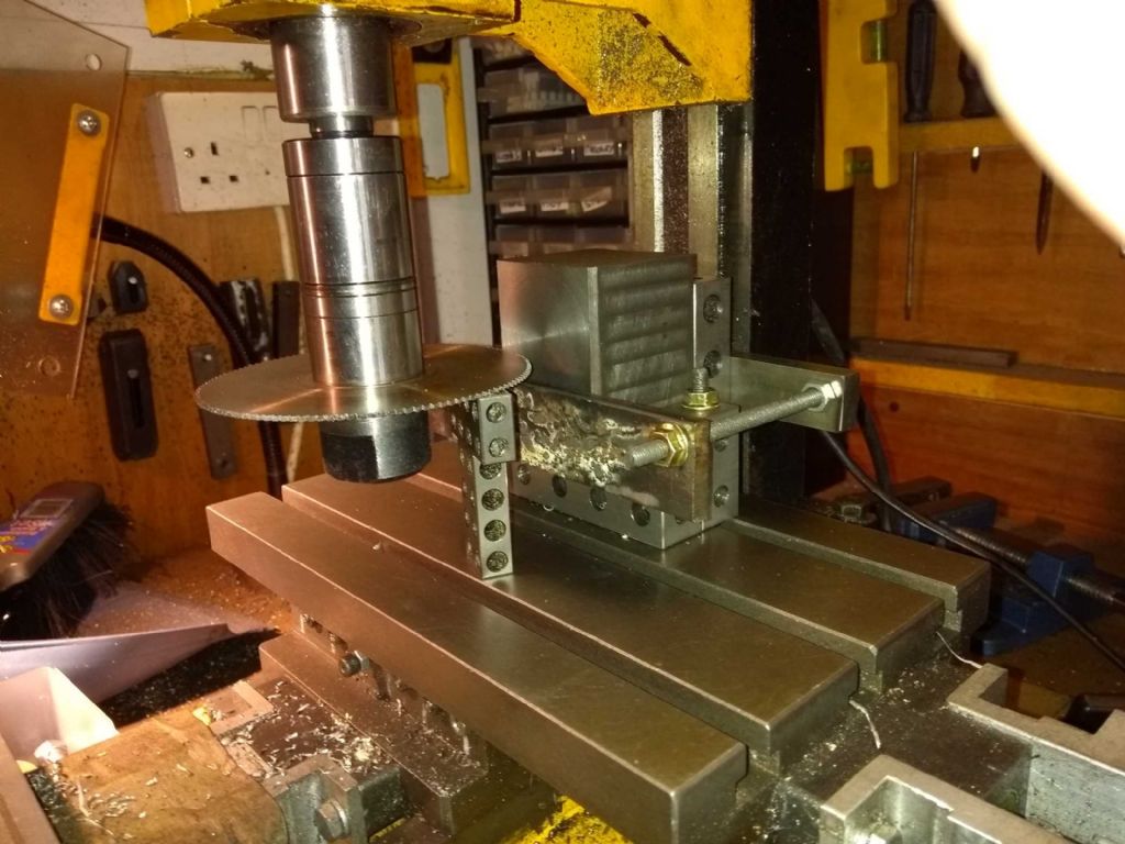
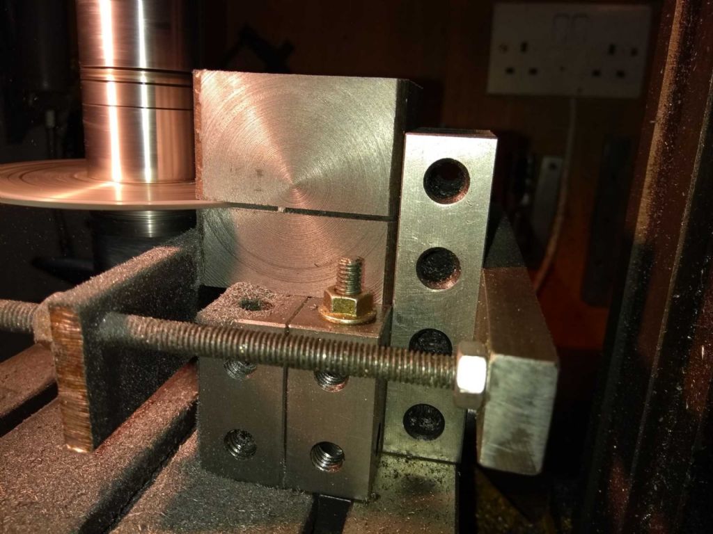
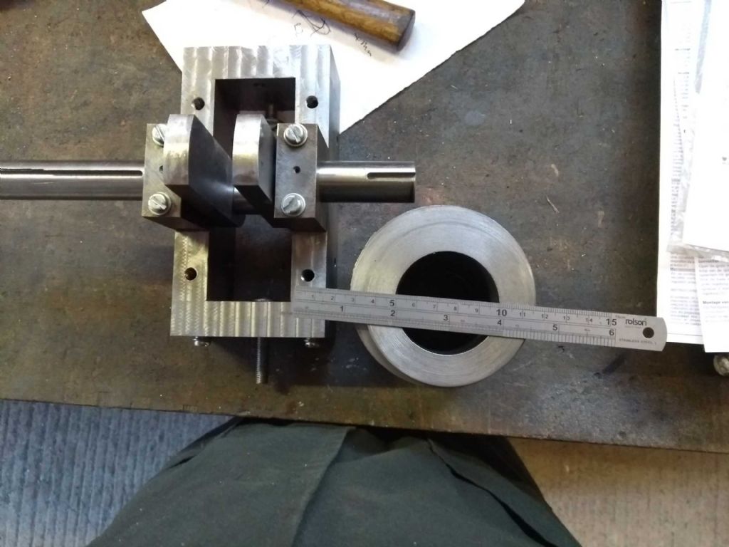
I wanted the horizontal split to be exactly 20mm above my base. I set up the slitting saw using some precision 2 4 8 blocks as below
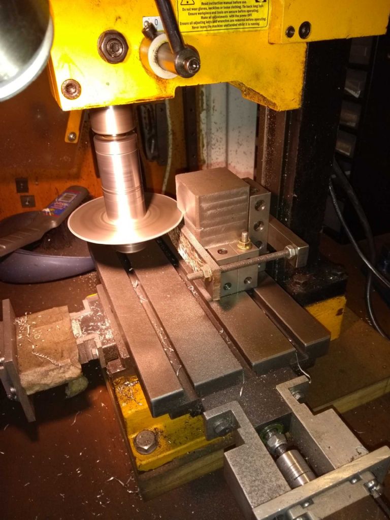
Of course the slitting saw would only get half way through so I needed to turn the iron round and saw from both sides
Nearly done….
and here is the result.
The astute among you will spot that the saw cut wasn't perfect. In fact there was a definite angle on each side leading to two facing ridges, each at half the width. I thought I could lap them out with some wet and dry on the surface plate, but this was just not working (given that the effective shape was convex this should not have surprised me. I ended up scraping to the point where it no longer visibly rocked.
The next cut, I planned to mill flat afterwards and measured accordingly.
Now for the boring part (so to speak)
then boring with a home ground hss bar. I think for the cylinder I will need to make a more substantial boring bar – there's too much flex in this.
In the end though it's not too bad. It might be a thou or two over but I think it will be alright.
Initially, I thought I'd screwed things up with the bore not being straight with respect to the base and sides.
Having remeasured, I'm seeing a drop of about 2 thou from to back, but that's comparable to the taper on the bore. The bore isn't quite centred but I make sure to drill and mount with the shaft in place so it will be reasonably OK.
phew! I dd NOT want to start this bit again.
Iain
29 December 2018 at 18:09 #388135Iain Downs
Participant@iaindowns78295Another couple of days of progress.
Firstly, I wanted to skim the crankase top and bottom to get some registration surfaces. MInd you with my little mill (CMD10) there's a limit to how nice I can get it – my attempts in the past to use a fly cutter were fairly abortive though I should give it another go now I'm a little less clueless.
This is the top of the crankcase. I did the underside with a 4 flute 10mm HSS bit and this with a 3 flute 10mm carbide bit. The carbide works so much better even on a final skim of a few thou. What's interesting is that you can just about see the 'crop circles' getting steadily worst towards the top left. the bottom right has the gibs fully engaged and the top left only just hanging on – the effects on rigidity are clear.
Next up was to drill the bearings through
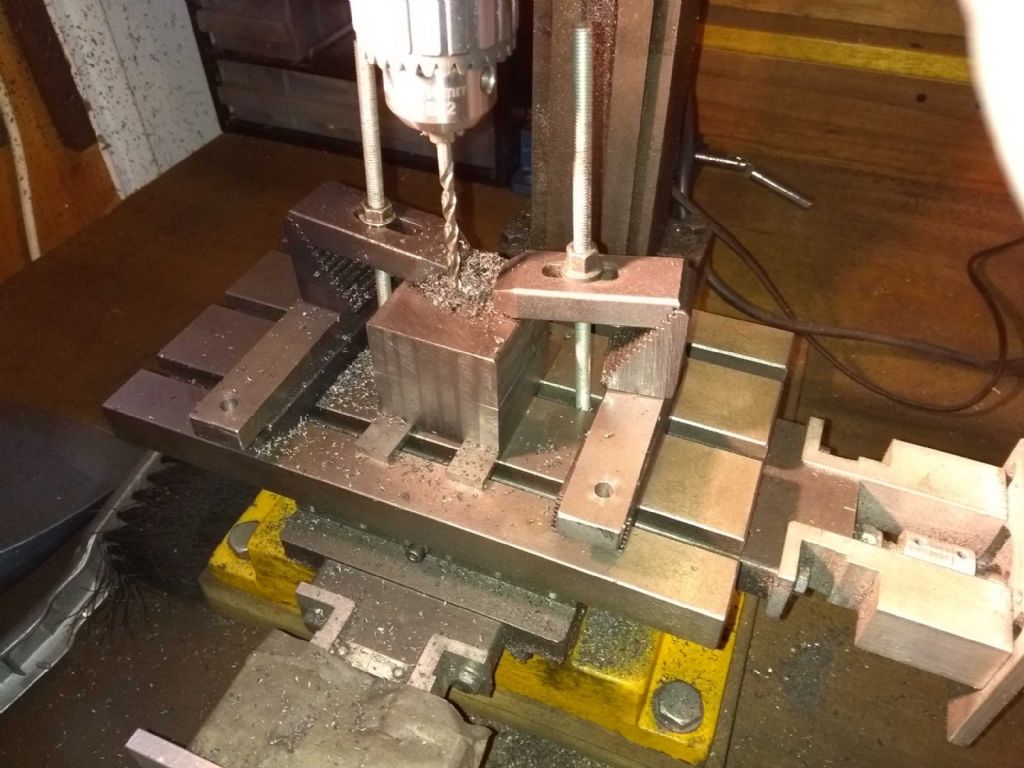
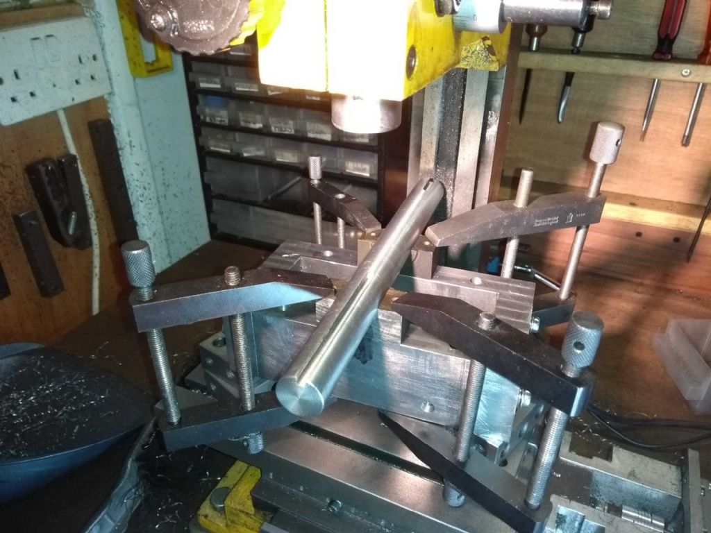
I'd left 3.3 mm pilot holes in the bottom of the bearings and the idea of this assembly was to drill through to the crankcase with the shaft as near central as possible and able to move freely.
Sadly, I discovered at this point that I'd mucked something up and the circular buffer bits (I have no idea what you call them) stick out a bit too far so that the journals won't fit. That's not a crisis – once I've mounted the bottom bearings permanently I'll just skim off a bit with my mill.
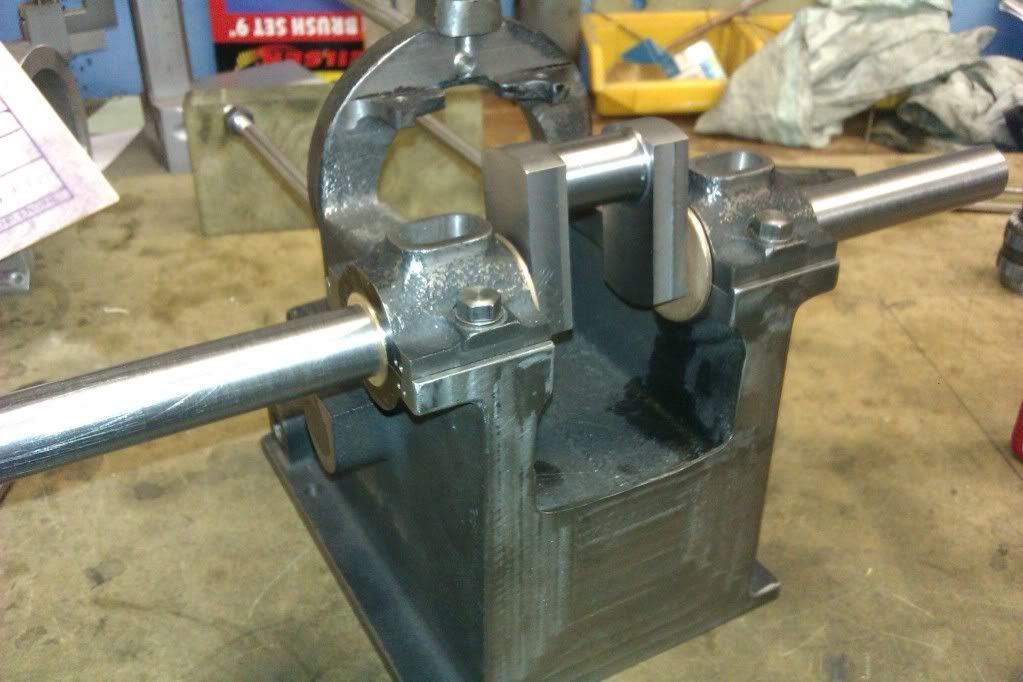
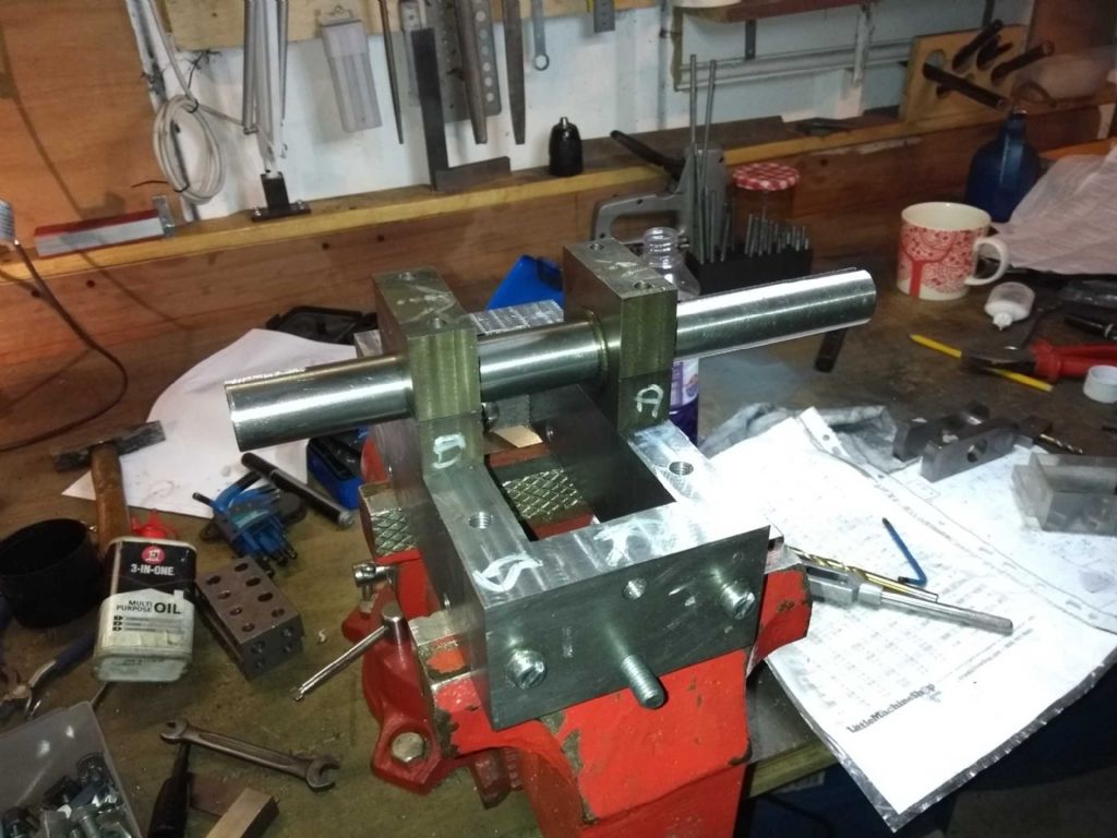
Here's is the work in progress with the bearings temporarily bolted to the crankcase.
As this stands the shaft is a little stiff but only slightly. It may ease up with some better bolts (the only ones I had have an angle on the head end which forces them into the centre of the hole, some cap heads or simliar may allow ab bit of movement. Of course I don't have any of the right length so will have to order some.
Once that's done the next task is to lap the shaft in place. I'm going to use this shaft (which will eventually be the real one (using parts of it which won't actually be in the bearings. The bearings are over sized by between 2 and 3 thou. Should I try and reduce this by slimming down the bearings and lapping or is that sort of OK?
Also, I need to put some kind of lubrication channel in I think. I was going to drill a 2mm hole through the top bearing. Should I turn a grove on the inside or will the oil get there just fine!
May be a bit of a break on this now – leave is almost over and I've a skiing trip coming up. Next major item is the cylinder which will be er, interesting.
Iain
29 December 2018 at 19:46 #388152 JasonBModerator@jasonb
With 2-3 thou clearance the shaft should turn quite freely, rather than lap it in blue the shaft and see where it is contacting the bearings and then decide on whats needed.
Oil hole should be fine on it's own
1 January 2019 at 17:55 #388722Iain Downs
Participant@iaindowns78295The 30th and 31st were eventful on the Steam Engine front.
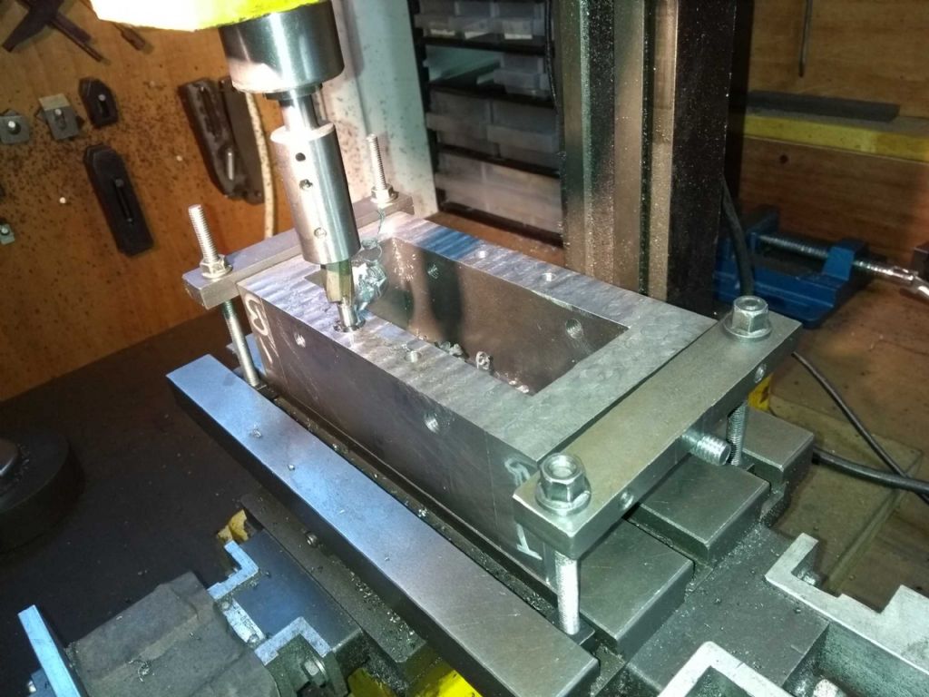
The first thing I attempted was to bring down the top of the bearing cap. To do this I thought I'd give the 17mm indexed face mill I bought a few years back and abandoned after it kept smashing the mill gears. Yes, I know it was the driver's fault not the tool!
Since then I have fettled the mill somewhat (and perhaps gained a little in experience), with the main improvement being an adjustment to mesh the gears better, after which (2 years ago) the gears stopped breaking. Maybe it wasn't entirely me after all…
The face mill worked really well. With some care I could take off 1.5mm in one pass, though it was too easy at that depth to overload the little motor and stall it.
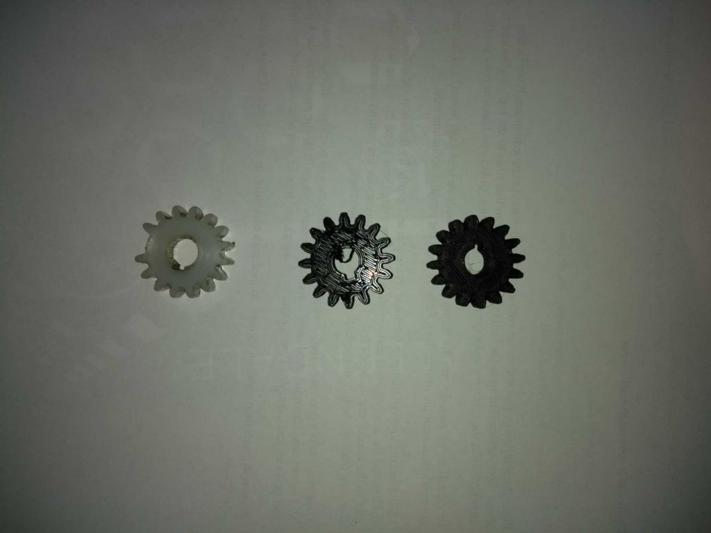
The thing I did wrong was to clamp it badly in my vice and it shifted. Which gouged the piece and stalled it. Also it turned out broke a cog off the motor gear. The mill still ran, and I finished off the bearing caps.
I have a box of spare gears for the CMD10, bought when breaking them was a weekly occurrence. Yes, you guessed. All the gears needed – apart from the motor gear.
I downed tools for the day and settled in front of the PC to call up Ketan's site. Then I thought, 'I have a 3D printer'.
A few moments with Onshape and I have a gear which looked like it was about right – it wasn't but it only took 20 mins or so to print. Armed with experience I printed a mod 1.5 16 tooth 8mm thick gear with a 3mm keyway.
After a bit of fettling (an 8mm reamer and a broach I'd made earlier) to tune up the bore, I fitted it and it worked!
First use was to counterbore the bearing bolt hole (now the bolts have arrived. Not too stressful and it worked a charm.
Next was scraping the bearings. This seemed to go better than my attempts at scraping flat. I think that one of the bearings is a little large and I have trimmed the faces of the bearing caps to tighten up a little. For one reason or another the bores are not quite in line with the base of the cap so I was scraping out at an angle.
The shaft blued.
Not the best of photos, but it's hard enough to see with mark 1 eyeball.
This isn't the final scrape by the way. I expect I could do better – the bearing surface on one side is quite good (lots of small high spots) – on the other side less so. In place I've got a horizontal rattle of 0.01mm or so which I think is reasonable. No doubt they will bed down.
Next was to use a 10mm carbide end mill to widen the gap so the journals would actually fit (and the new bearing coped well with this at 2000 RPM).
Then it was 'call it a day'. I still need to glue the shaft, pin it and cut out the middle. However, I like to quite whilst I'm ahead – had I buggered something up it would have spoilt a decent couple of days of work!
I could of course, have completed this today, but I felt weary and a little unwell for no reason I can quite put my finger on. My wife claims it was the copious amounts of red wine in celebration of the year and (and, as it happens, my birthday), but that hardly seems likely to me…
With best wishes to you all for 2019
Iain
4 February 2019 at 21:02 #394725Iain Downs
Participant@iaindowns78295So it's month since my last post. My time has largely been taken up with work (ugh), a weeks skiing in France (cold) and a week with customers in Toronto (very cold).
I've also quit my job so will be a happily free man in a few weeks – though hopefully not for too long. If anyone wants a brilliant software designer/architect/manager type person then drop me an IM! (am I allowed to advertise, Neil?)
But back to the real world. I've got round to gluing the main shaft of the crankcase into the journals, but not yet drilled, reamed and bashed for pins, cut through the shaft and tidy up. This weekend probably.
Instead I've started work on the cylinder. The first thing was to make a boring bar to take an HSS bit. I've an indexed boring bar with a carbide bit, but experience has shown that it won't cut dead parallel when finishing off a cylinder.
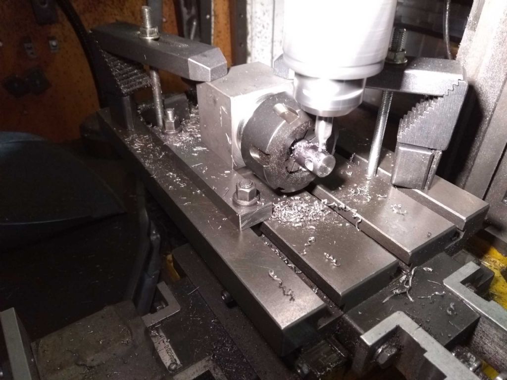
This gave me a good excuse for buying a square Stevenson's block with an ER32 collet holder.
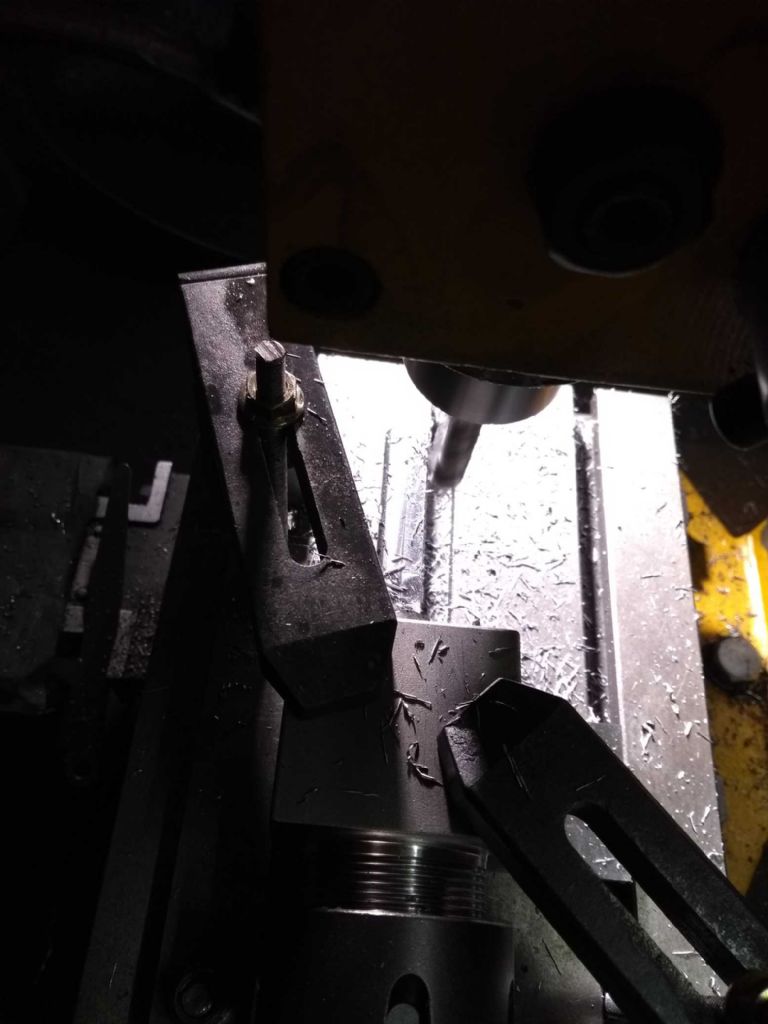
I have some 13mm rod which I cut and faced, set in the collet holder, stood on a couple of parallels and pushed against a bit of 10x20mm bar aligned with the table and against a set bolt to register it (you can't see that in any of the photos)
This is me squaring the end to fit in the tool holder. It's a terrible photo really!
Next find the edge with a wobbler. Which disintegrated in the process (the rod came out of the ball), but some locktite fixed that.
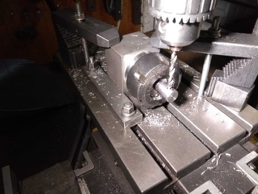
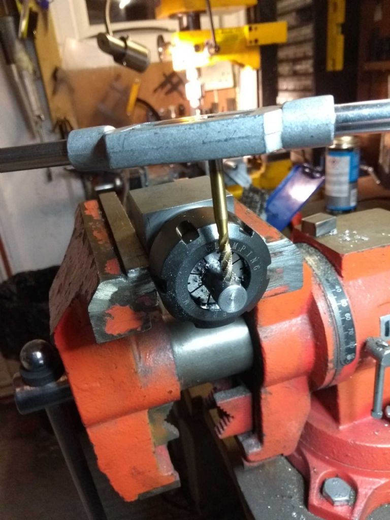
Centre drill to spot the hole for some 6mm hss bar, drill to about 4 mm then to 5.8.
you can see how the block is held and registered a bit better in this photo.
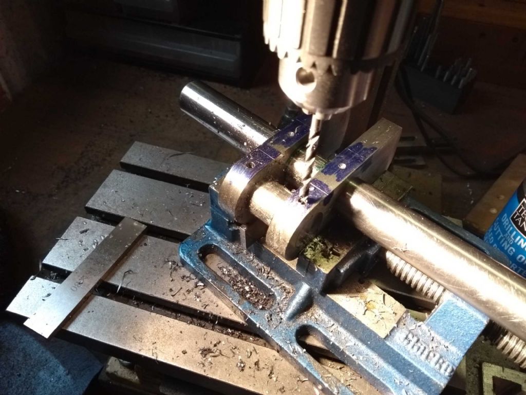
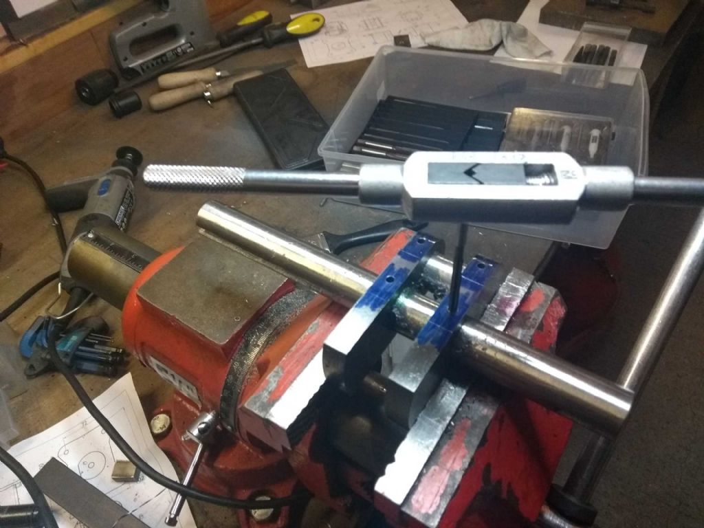
Turn the block through 90 degrees, centre drill and the drill through with a 4..4 mm for the M5 grub screw.
Finally, ream the bit hole to 6mm and tap the grub screw hole
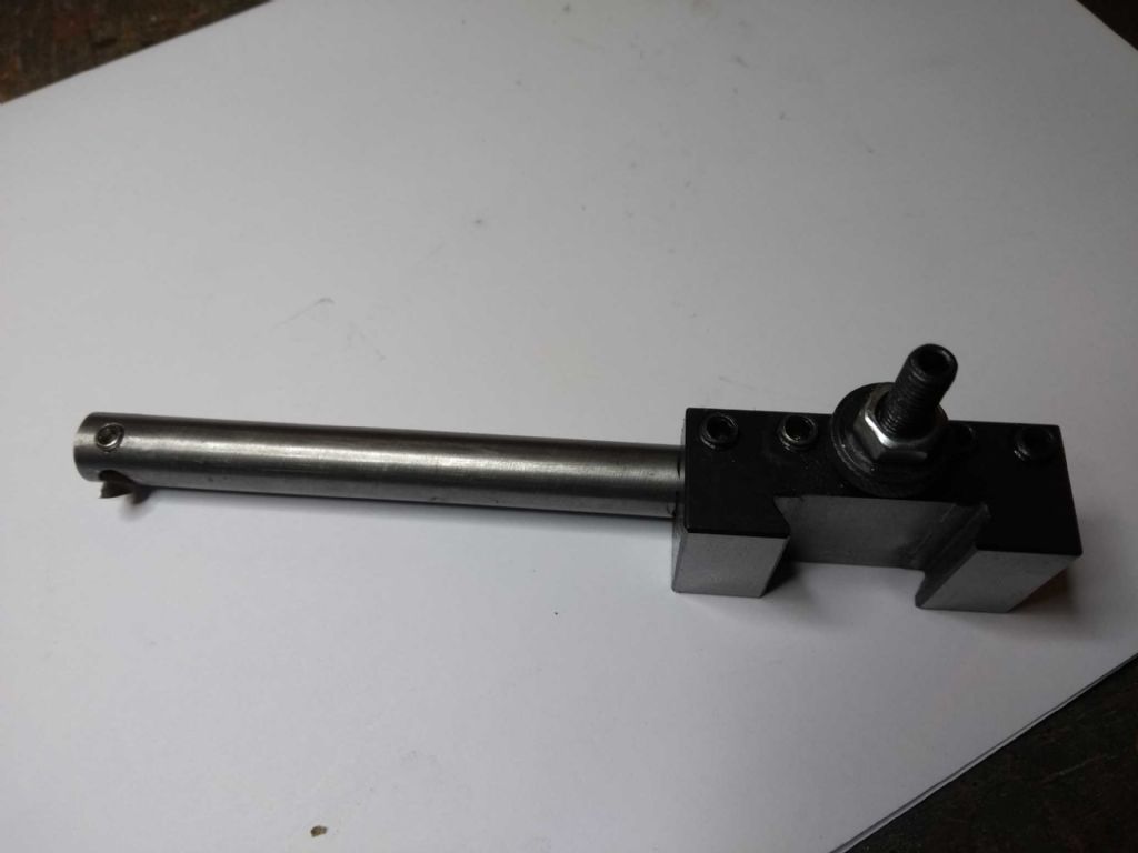
And here's the finished product!
I don't think I've got a good profile on the bit, but that's easy enough to regrind..
The other thing I've started on is the cylinder.
Somehow a complex work of art must emerge from the dull envelope…
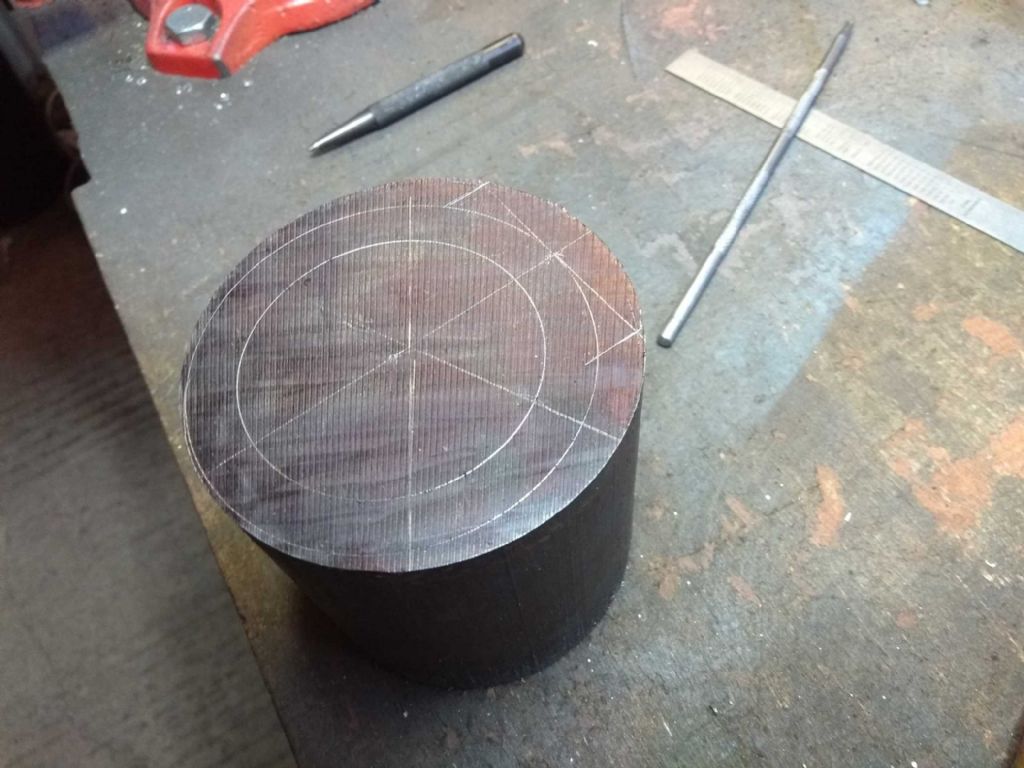
I started off by finding the best end (one end was quite flat and square, the other not so much) and squared the other end up in the mill.
I don't really know why I did it this way as it would have been quicker and easier in the lathe.
And then marked up to make sure that the cylinder actually fits in the er, cylinder and to find the centre for boring
Is this how Michelangelo felt when he first dragged his charcoal across the marble that would be David?
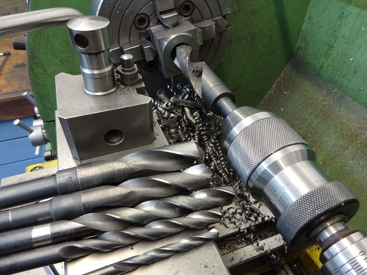
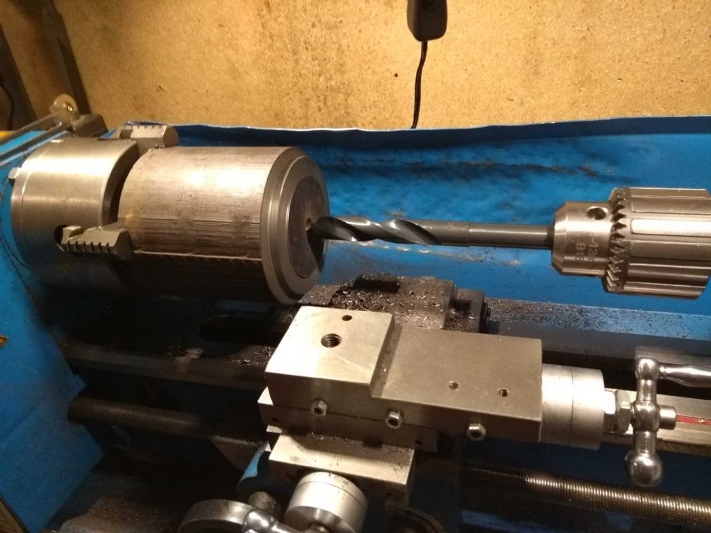
I've also invested in some long drills. It's all very well having a stiff boring bar, but you still need a hole to bore out from!
I've got a bunch of them from 2mm up to 10mm – does anyone have advice on the best size to start from? The chances of a 2mm drill getting through 85mm of cast iron seem remote, but I don't know how easily a big drill will go through.
Or am I approaching this the wrong way and should start with some other sort of drill?
Iain
4 February 2019 at 22:17 #394732Dennis R
Participant@dennisrIain
Your ER collets are not properly inserted into the collet nuts.
The collet should be practically flush with the outside face of the nut.
The collets clip into the top inside eccentric lip of the nut.Dennis
5 February 2019 at 07:09 #394746 JasonBModerator@jasonb
Start with a 6mm standard length jobber and go in about 40mm. then a 10mm and go in 30mm, you can then go back to the 6mm drill and cut a further 25mm. Now another 25mm with teh 10 and then start part way with say 12mm. Then if you have any blacksmith drills open up further with those.
The basic idea is that you don't go in areally long way with the drill so less chance of binding and you don't need to back the drill out as far to clear swarf.
As said collet should snap into the nut which will then pull it out of the taper when undone see this
 5 February 2019 at 07:36 #394748
Iain Downs
Participant@iaindowns78295Dennis, Jason. Thanks for the advice on the ER32. It would seem that my foray into engineering merely reveals an increasing vista of ignorance – soothed only by the knowledge and advice on this forum.
And thanks for the advice on drilling, Jason. Very obvious once you're told!
I have a 15mm blacksmith's drill on order.
The only thing that surprised me is the size of the starter drill. I would have thought that a 6mm would be quite slow and to get through the solid metal.
What sort of speed should I run this at? I tend to be cautious on speeds (fear and ignorance).
Iain
5 February 2019 at 07:53 #394751 JasonBModerator@jasonb
I'd probably be at 8-900 rpm for the 6mm. Drop to say 600rpm for the 10mm and around 300 for your 15mm.
Should not be a problem getting into the metal with a 6mm provided it is sharp.
16 February 2019 at 17:07 #396592Iain Downs
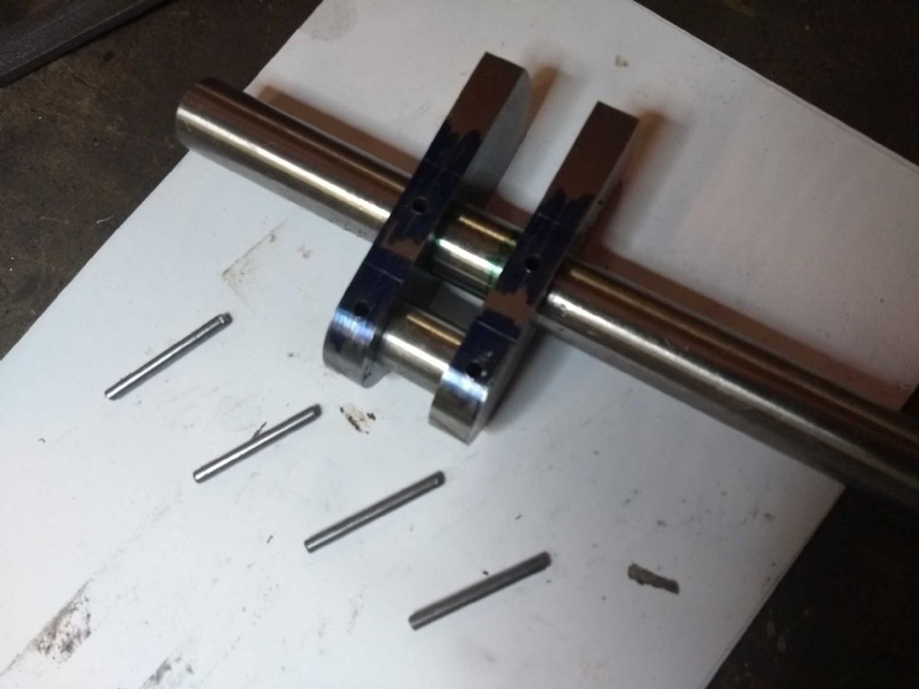
Participant@iaindowns78295So after a few weeks of distraction (and to be honest, the shed being far too cold to face), I've finally 'finished' the crankshaft.
All that's left is to pin the crank and the cut out the awkward bit of the shaft.
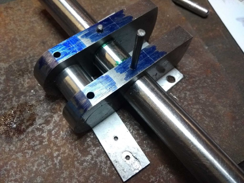
Drilling the pin holes (to 3.9mm)
Then reaming
The metal for the pins was source from a specialist retailer – B&Q! I have no idea what sort of steel it is.
However, before using them I performed extensive malleability. That is I hit the rods with a hammer and made short the dented and spread. Precision engineering at it's finest.
Which was carried through in the delicate insertion and fixing of said pins.
The 'anvil' was a small piece of inch plate sourced from a scrapyard. I wasn't terribly good at this bouncing around somewhat. Which (I'm claiming0 is why some of the pins bent and stuck and I had to push the other half in from the other side.
Curiously, I found that despite being assembled on a surface plate with some care and being glued good and proper the journals are not (any more?) totally in line (about 0.25mm out from one end to the other). I'm rather hoping that the shafts are in line!
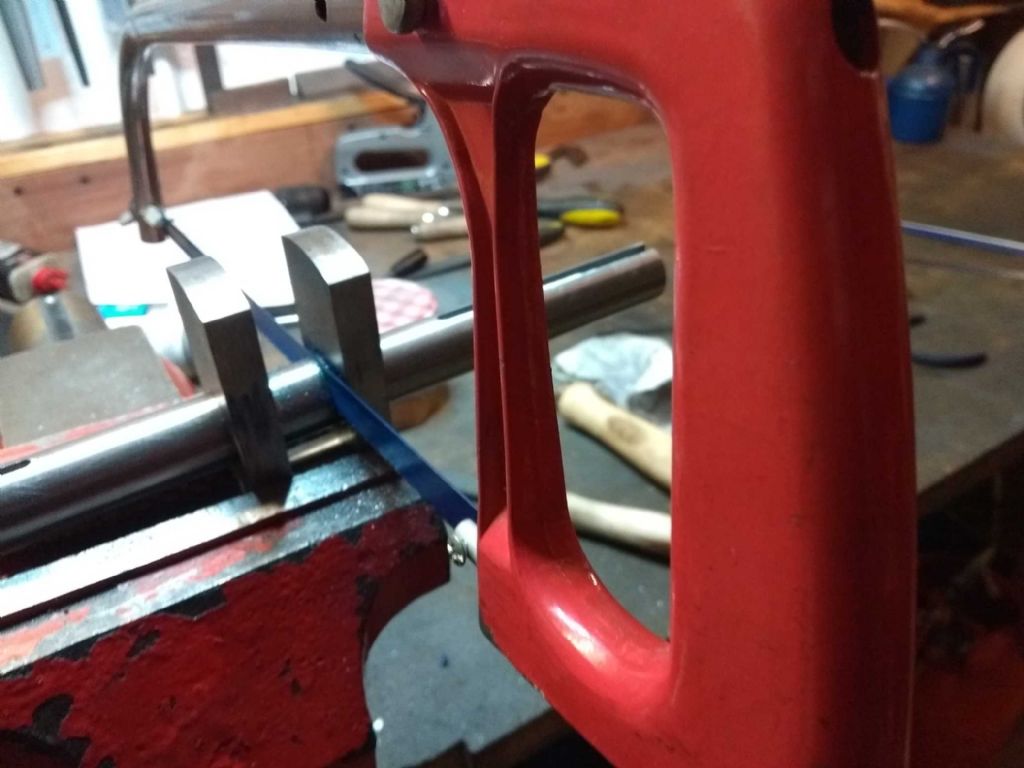
Next cut out the middle bit
I used the mill to take the bulk of the left over material ( one or two mm) and then finished with a file.

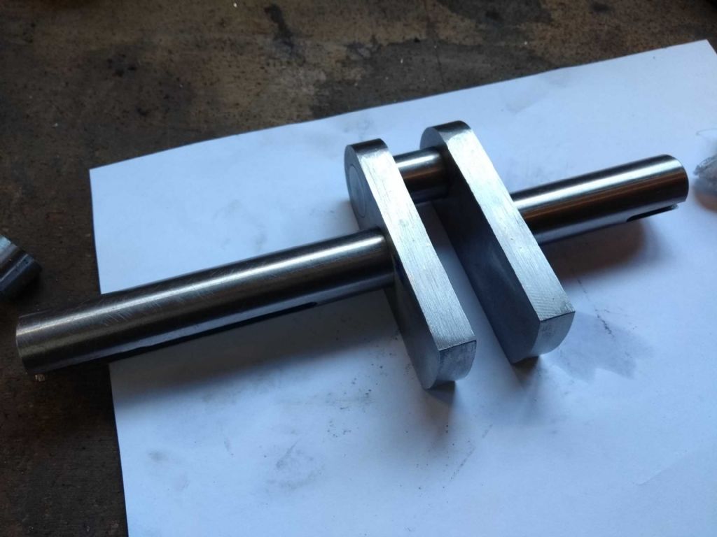
Tada! A Crankshaft.
Iain
16 February 2019 at 17:20 #396594Iain Downs
Participant@iaindowns78295And not content with finishing the crank, I immediately started up on the cylinder.
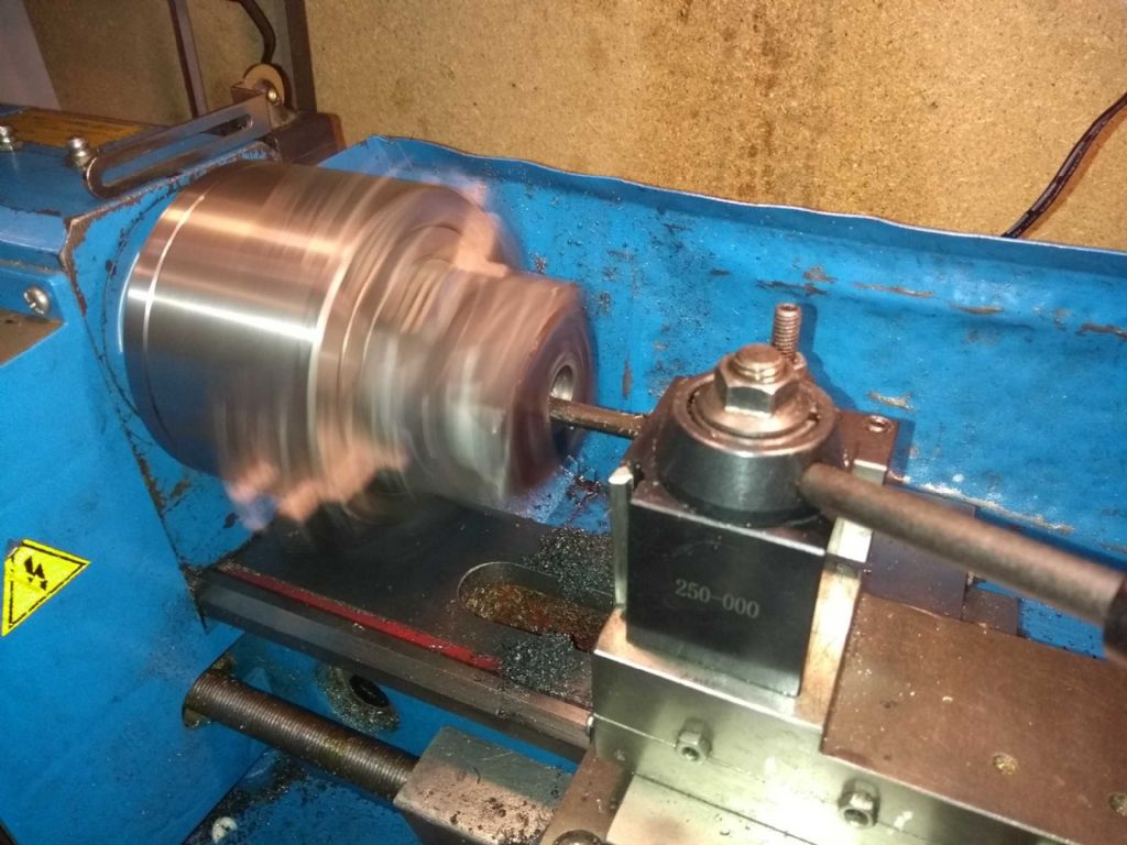
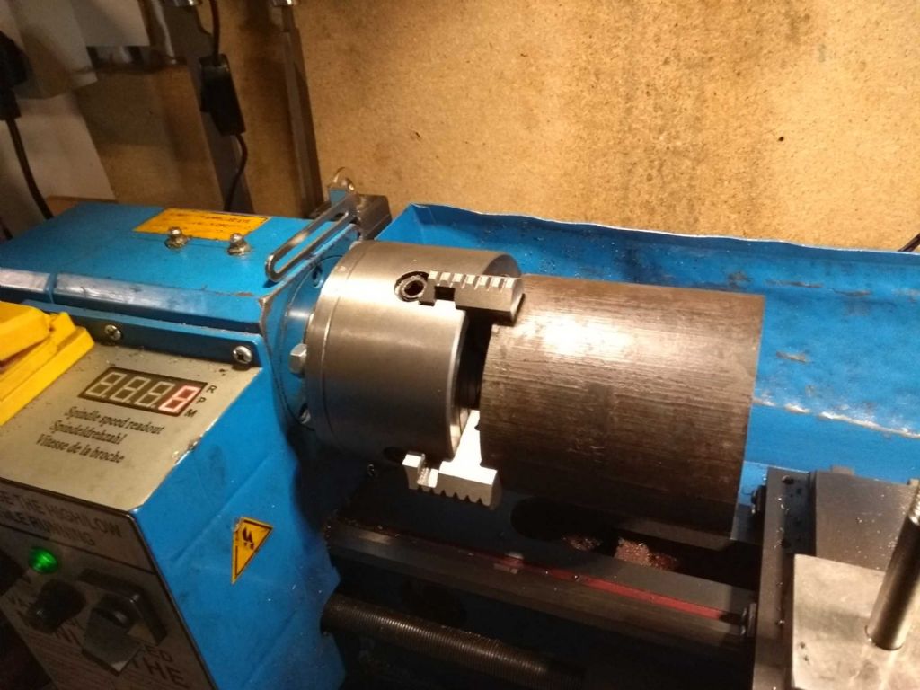
I mounted it on the lathe in a four jaw and centred it on the markings I'd set in a previous job.
I must say that seeing that enormous chunk of iron on what is a fairly small lathe was a bit daunting. I'm slightly worried about it handling a 50mm bore through the length without shifting.
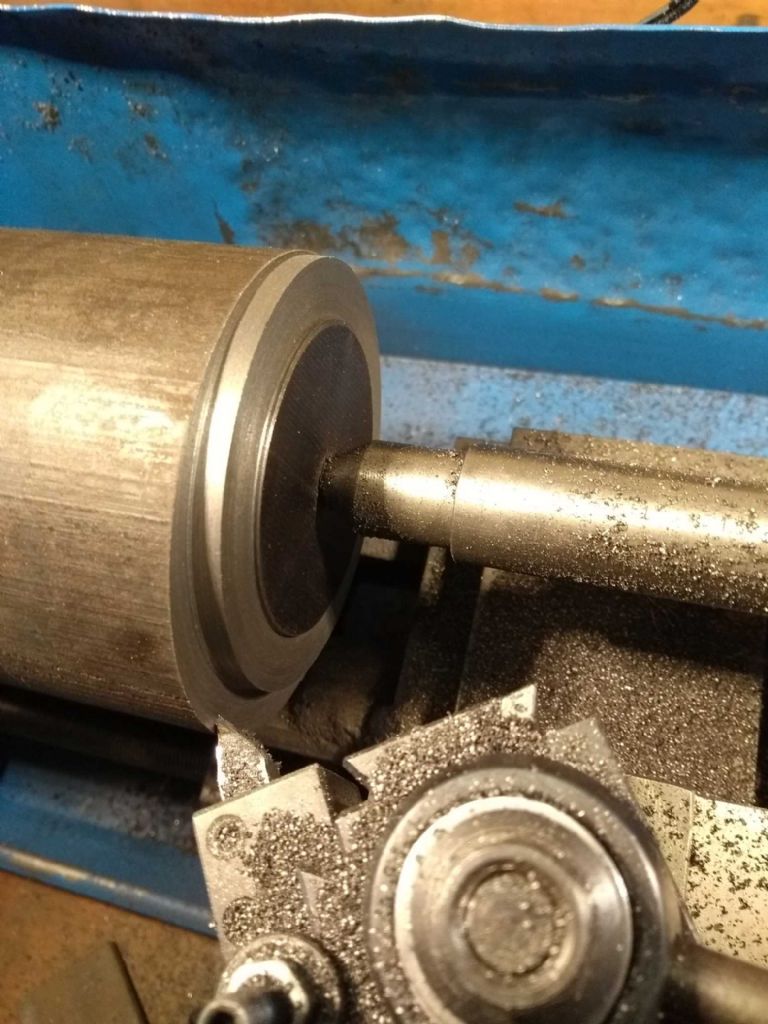
For today, however, the task was to cut out the flange at one end of the block. This I could do with a centre adding some support, though the sheer size required me to cut a wierd shaped tool so that I could physically get to the material in the right place (and still provide access to the centre and tailstock.
There's a depressing thought here about how much cast iron dust I will be making in the next phases. More than half the volume. Do you think I can sell it back to the supplier?

I'm afraid I'm going to have to ignore Jason's (most excellent) advice on drill speeds. If I were to run this at 800 rpm, the lathe would walk out the door – probably over my dead body!
I can get it up to a bit under 300 rpm before the vibration gets too much. the work above was done at around 200 rpm with fine cuts (0.25mm) and a very gentle feed. Any more than that risked stalling and a jam and release set it of ricking back and fore in a most disturbing way.
For the benefit of anyone as innocent as I, the cut is very much an interrupted cut on quite a large diameter (for a tiny lathe), so each rotation there is s significant change of load as it goes from not cutting to cutting. Poor lathe.
Still we've survived. Next is to drill out to as big as I can go (14mm I think) and then gently bore out another 36 mm – gently!.
Iain
21 February 2019 at 17:37 #397348Iain Downs
Participant@iaindowns78295OK a bit more done.
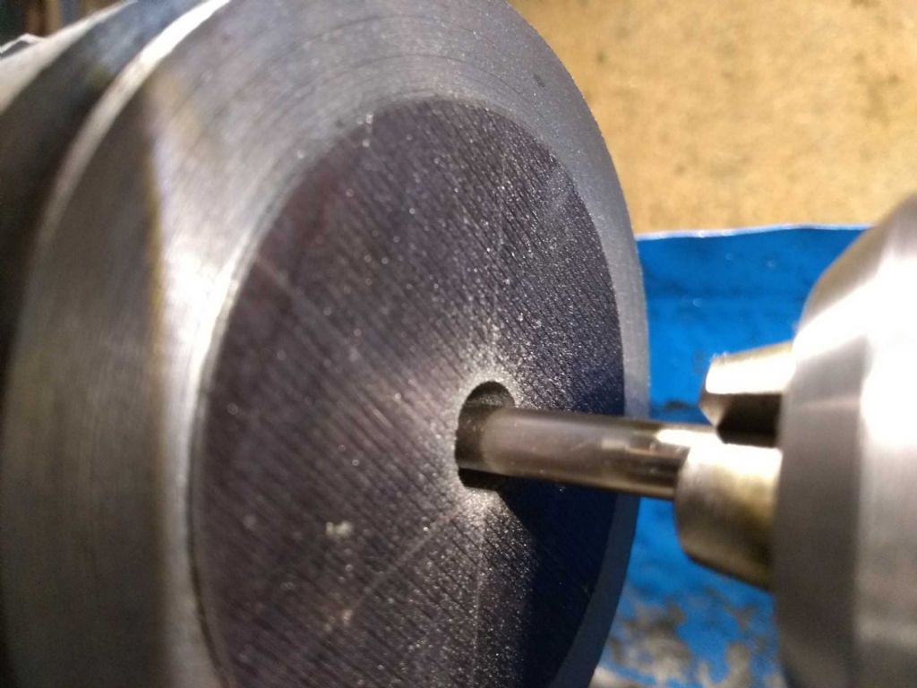
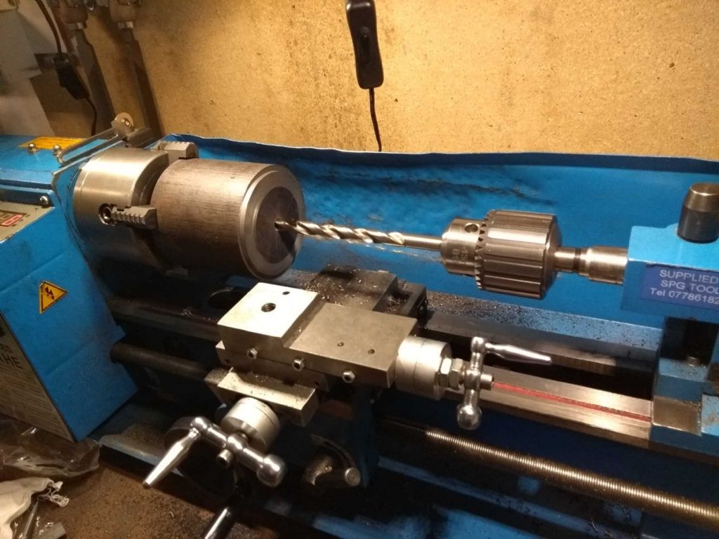
Following my Sage (Jason), I've drilled a bit with 6mm then 10mm then more with 6mm and so on until through. Then a push through with a Blacksmiths drill.
On thing which I saw here is that the drills seemed to swing up and away as it entered deeper into the hole. This particularly with 6mm as the 10mm filled the space.
I don't know if this is just the torque pulling it out of centre or if the tailstock is contributing to this. I have measure the tailstock as about 0.25mm higher than the headstock on a test bar and with a 2MT just this week found that the bar points upwards from the tailstock by about 0.1mm in 100 mm.
Having a good sort out of the tailstock is on my todo list (bolstered by a purchase at Doncaster 2 years ago of a lapping plate I've not used!). But it's going to need a bit of girding of loin cloths to get the courage to start it!
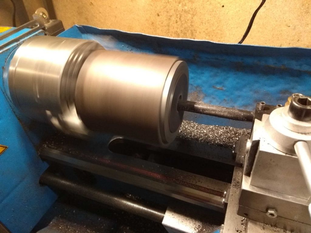
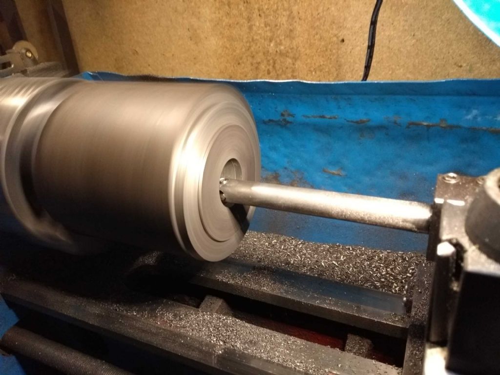
Next was to bore out. FIrst with a smallish carbide boring bar and then with the hss indexable boring bard seen in earlier posts.
and here's my boring bar. My first attempt at a tool bit wasn't very good and it needed careful alignment so as not to scrape in the early stages.
But, dear God, this is going to take a long time! The raised part is more or less where the cylinder bore should be.
Number one skill for model engineers? Manual dexterity? no. technical drawing skills? No. Mathematical insight? No.
Patience?
Iain
24 February 2019 at 18:47 #397808Iain Downs
Participant@iaindowns78295After spending a goodly amount of time watching my hard earned pennies turning into cast iron dust, I've finally got the bore through the cylinder.
As best I can tell I've managed to bore this to exactly 50.00 mm. I'm measuring the bore with (Aldi) digital calipers and I'm confident neither in their accuracy nor in my ability to use them with this precision. Still….
One thing I realised after i'd started the whole process off was that the bore was wider than the gap left by the 4 jaw chuck.
Accordingly the last 3 or 4 mm were not bored all the way through. This isn't a crisis as I need to take a bit off the end anyway. At least I hope it's not a crisis.
The next step is to turn it round, reduce to the right length and cut the other end flange. As I have only a 5mm ridge to grip onto (with an 85mm long chunk of metal) I felt that I should secure this better.
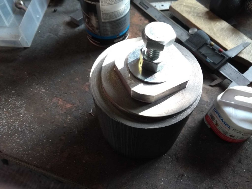
The idea is to have a disk which I can clamp through the central bore. Not having anything particularly appropriate, I took a 50mm square aluminium bar cut a bit off the end (my chop saw does not like me now) and trimmed it.
I can remove and trim off the what's left once the challenging intermittent cuts on the outside are complete. I hope.
Note, regular readers, that I managed to insert the collect correctly in the holder this time!
And here it is sort of complete.
I was going to carry on, but my lathe appeared to develop asthma. It wheezed and grunted and refused to get up to speed.
I could stop the spindle with moderate finger pressure.
Since, I've left it to cool down (though it's not been working hard) and went back an hour later and it seems OK.
I may well be begging for help on this in the forum, but I'll make that a separate post.
Iain
9 March 2019 at 16:20 #399408Iain Downs
Participant@iaindowns78295We left the last post with our intrepid hero concerned that he might have broken his lathe.
He had.
It would seem that the interrupted cut was too interrupted (or the hero too brutal?) and the sacrificial motor pulley had duly thrown itself on the alter of sacrifice.
I did give some thought to printing a new one, but given that (in theory) the pulley was designed to break the internal key and not the motor, I wasn't sure that it would have quite the same shear characteristics. So out came the chequebook (metaphorically) and £6.50 worse off I got a replacement (I got two actually – one way of making sure things break is not to have a replacement).
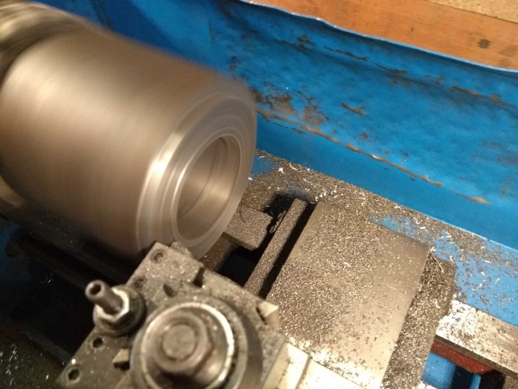
With that I set to and finished of the lathing part of the cylinder.
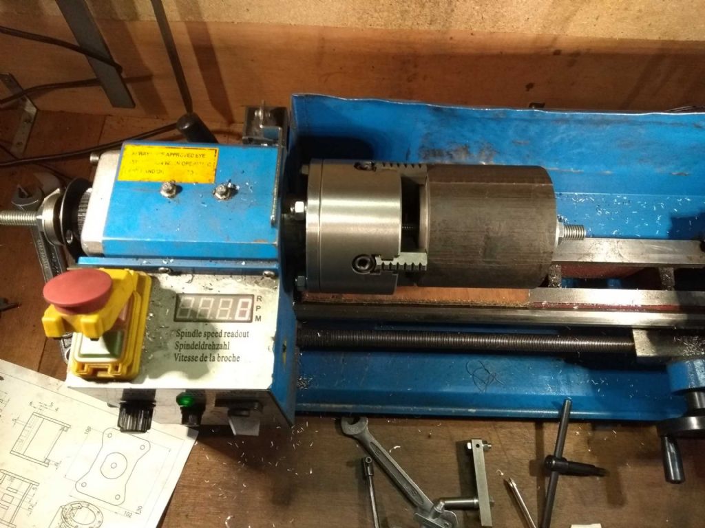
As the cylinder was now held less securely in the chuck (just the 5mm of the flange) I wanted to make sure that it was held in place hence a rod through the headstock pulling it against the chuck. As you see below.
Once I'd got the outside trimmed down I could finish of the end proper with out the bolt.
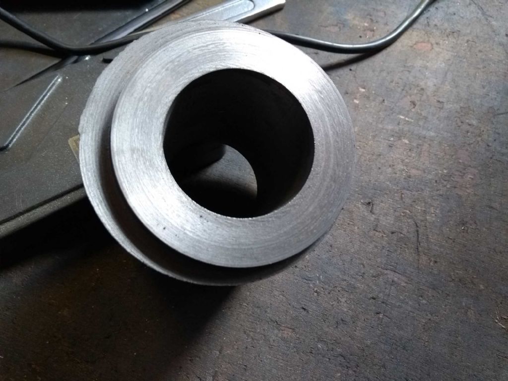
So the 'finished' product…
The cylinder is about 0.25mm too short. This is due to something that happened just before the finishing cut when the cross-head seemed to jump forward for no apparent reason. Clearly this was something I did, but I really don't know what. Perhaps I nudged the dial with an elbow. A bit annoyed at that as I was creeping up on the exact length (to the various limits of my ability and measuring devices). However, it's not going to stop it working.
Now all I need to is remove 2/3rds of the remaining metal on the mill. Shouldn't take too long on my CMD10….
Iain
9 March 2019 at 23:58 #399483Paul Kemp
Participant@paulkemp46892I love this thread for a number of reasons; it's something different, not too serious, not seeking the last tenth of a thou, using machines to their 'full' capacity……. Great, well done, keep it up.
Paul.
10 March 2019 at 16:18 #399597Iain Downs
Participant@iaindowns78295Hmm.
Describes me to a T.
Not too serious, terribly inaccurate and overambitious with projects…
But many thanks indeed, Paul.
Iain
11 March 2019 at 16:08 #399748Iain Downs
Participant@iaindowns78295The benefit of unemployment is that it gives me a bit more of a chance to create cast iron dust and I duly managed this today. One hopes to keep working on the Steam Engine, but the wife wants me in a job. Sigh…
About my first book on engineering was one the Mr Hall's books. This one on milling. In it the first thing he says is that the main challenge in milling is working out how to hold the workpiece.
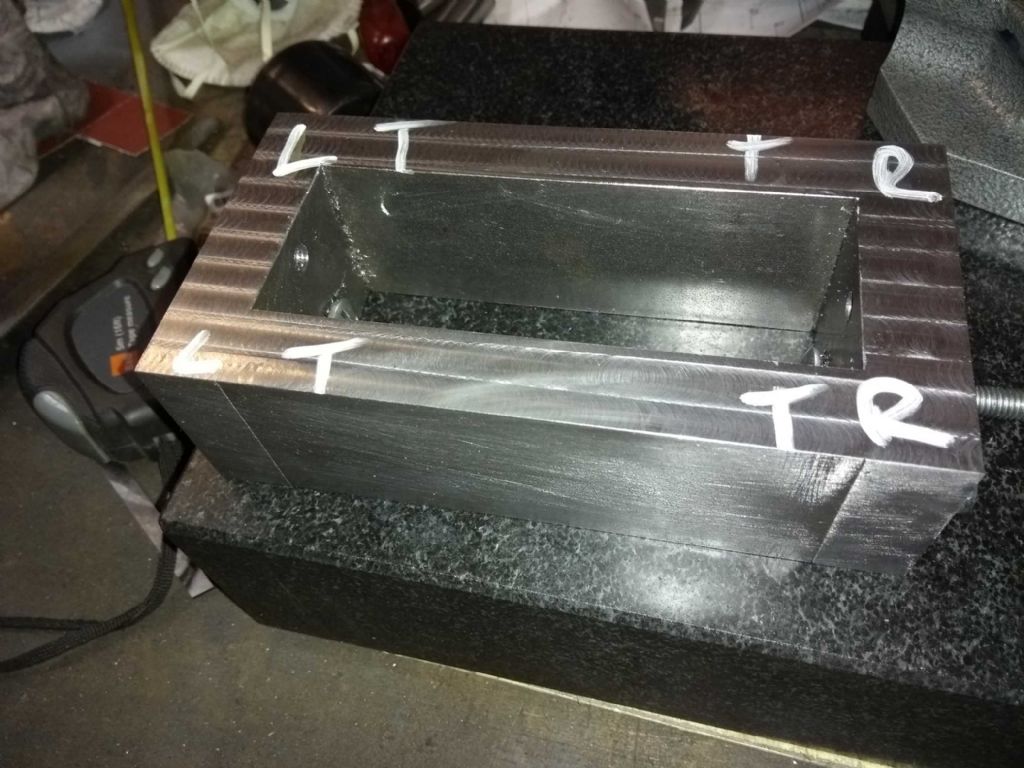
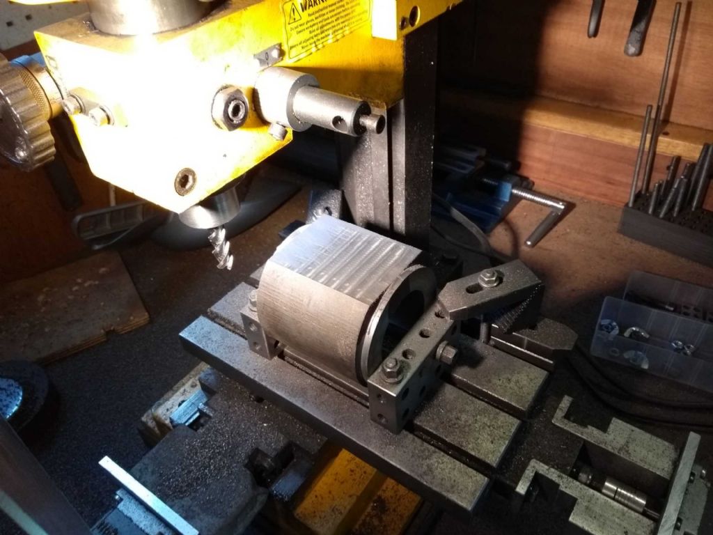
I'd agree with that, and it took quite some puzzling to work out how to hold the partial cylinder accurately with the thick piece uppermost. One of the things I realised is that it didn't much matter if I got the exact thickest part uppermost provided that I could get a wide enough cut for the valve face.
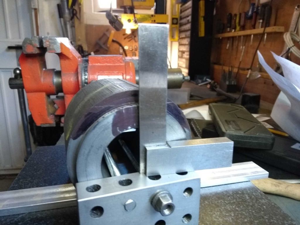
So this is what I came up with.
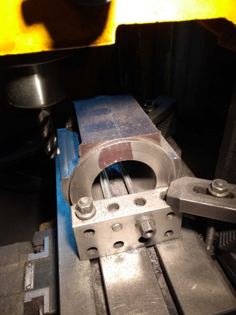
The ally bar is to raise it a bit (for assembly, then removed). The two Stevenson's blocks are clamped to cylinder ends which are (I hope) normal to the bore. Finally, the rotation is checked with the T square – you can just see the scribed line if you put your good glasses on!
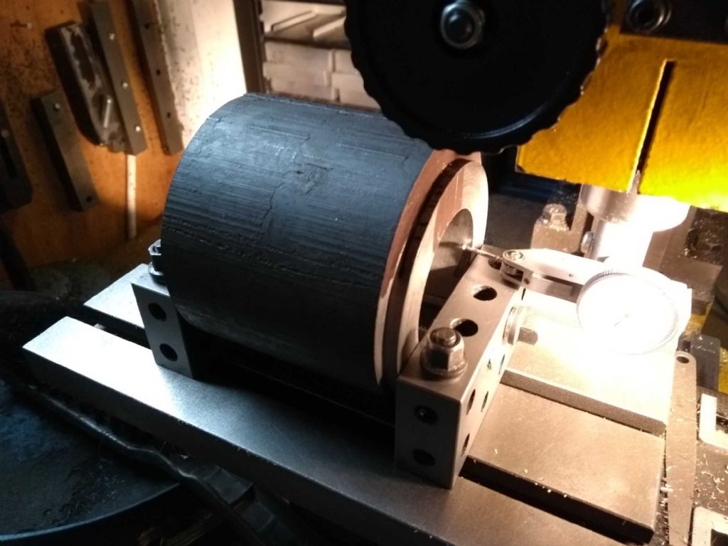
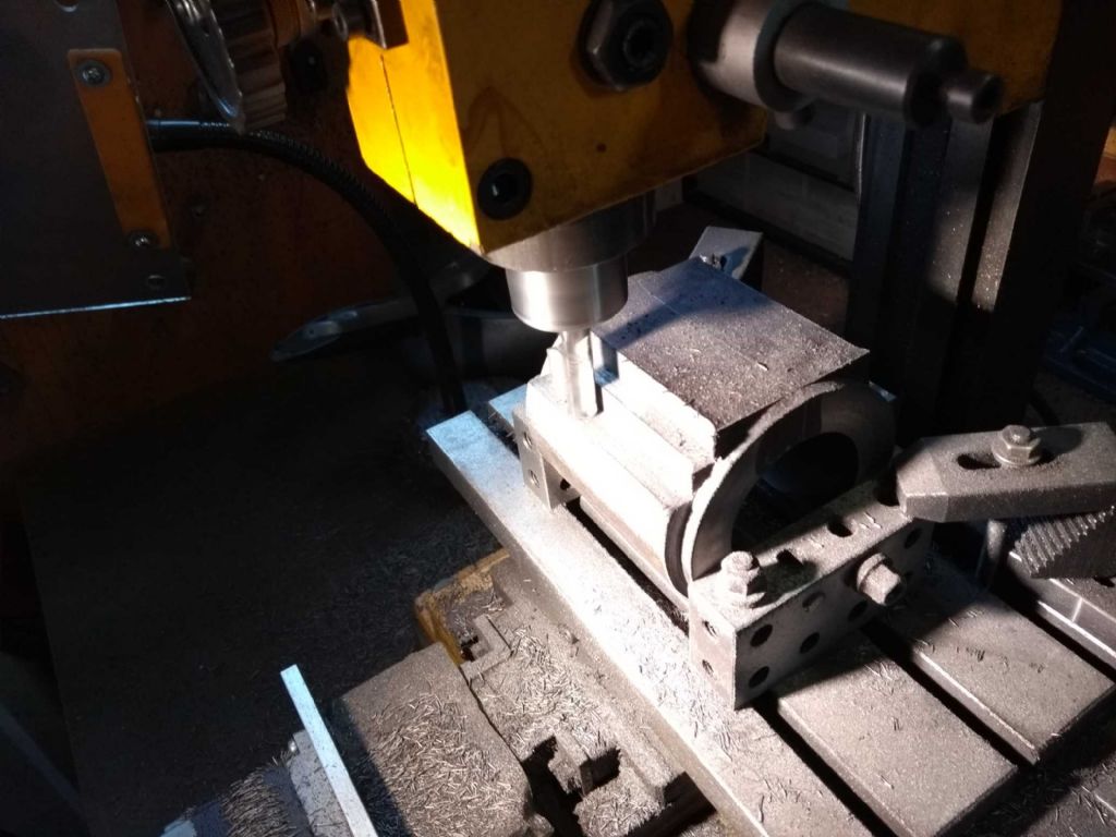
Next to mount it on the mill
The reason for raising the piece is mainly so that i can get the indicator at (more or less) centre height.
Finally, the drudgery of slicing of the top at 1mm doc at a time. With a 3 flute carbide mill that goes quite nicely albeit slowly.
So next up is to square off the sides. I', trying to work if I should cut the valve ports on the top now, whilst It's in place or if I should wait until I've thinned down the outside.
I'm also seriously wondering how I'm going to mount it on my 4 inch rotary table. On the rather small worktable.
I was hoping to (somehow) use my Christmas present tailstock, but that really won'f fit. I suppose the good news is that I really am just throwing the outside away so there's no particular need for high accuracy.
Iain
19 March 2019 at 20:38 #401289Gas_mantle.
Participant@gas_mantleHi Iain,
I've just seen your thread and it looks like you are making great progress, I was recommended to read about your build as I want to build something of a similar size as a horizontal engine. I haven't read through the thread in it's entirety yet but it looks to be an interesting one to follow.
My hope is to try to cut a large cylinder about 60mm bore from a 85mm cast iron square bar, I wasn't sure it it was practical on a hobby machine but it looks like my lathe and mill are similar a similar size to yours.
I look forward to an update on your progress.
19 March 2019 at 21:04 #401292Iain Downs
Participant@iaindowns78295So continues my drive to discard the large part of a perfectly good cast iron cylinder.
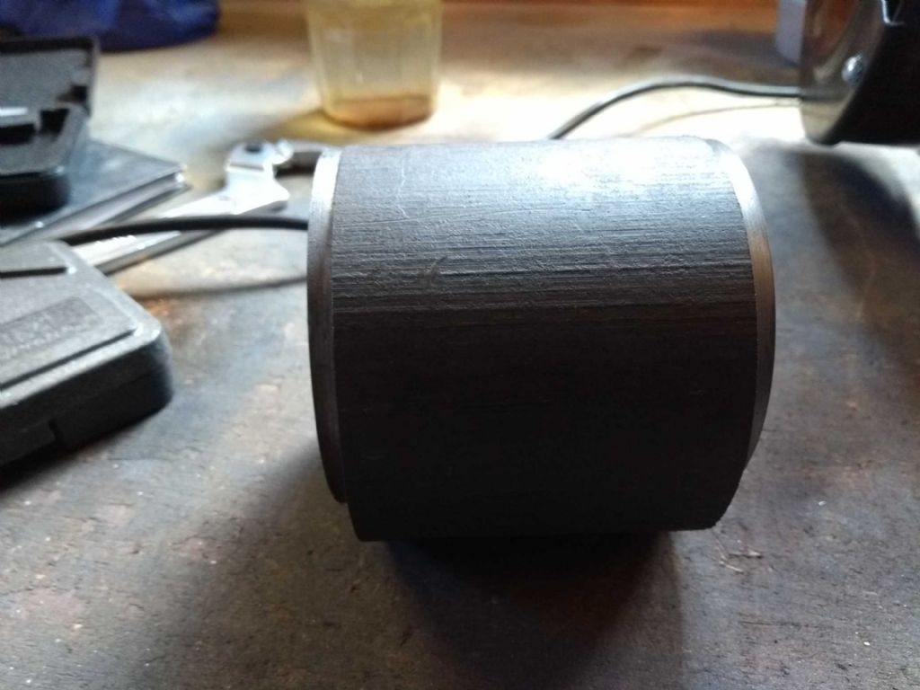
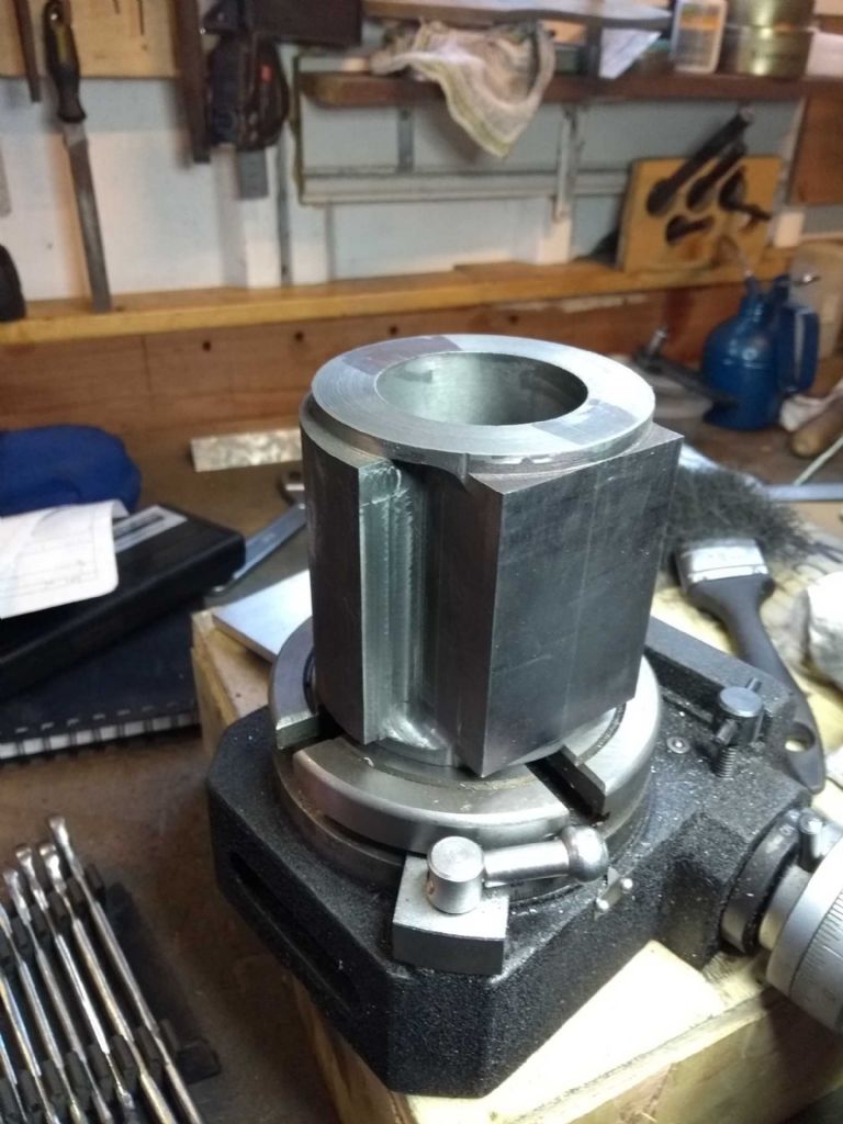
In the previous post I'd machined the top of the valve port. Next was the sides.
I did this in steps of about 10mm with a 1mm DOC.
And the finished block (for now, probably needs a bit of tidying once the rest of the bar is removed.
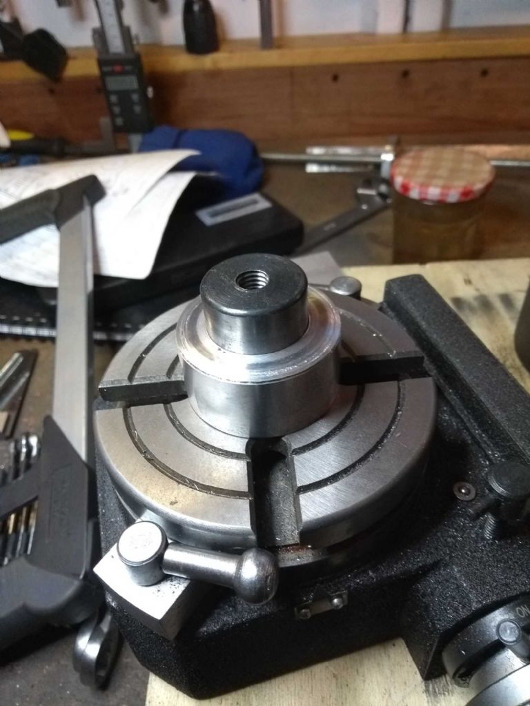
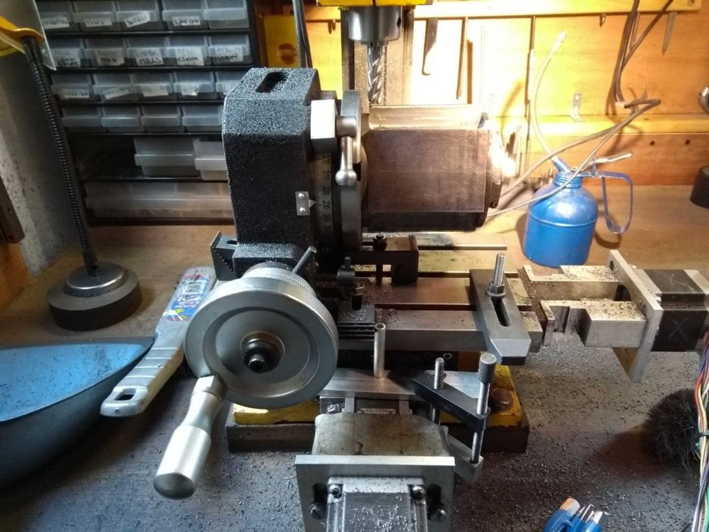
Next: How on EARTH am I going to mount this vast chunk of metal on a rotary table on my tiny mill?
That's the general idea. A chuck is impractical for a number of reasons. One of which is that by the time I have a decent sized chuck on there and mount the cylinder, the cylinder would be off the edge of the table! Another is that I did not think that the 5mm flange would provide enough grip. Boy was I right about that! (more on that later).
In the end I decided to use an MT2 blank, a clyindrical spacer and a clamp on the top.
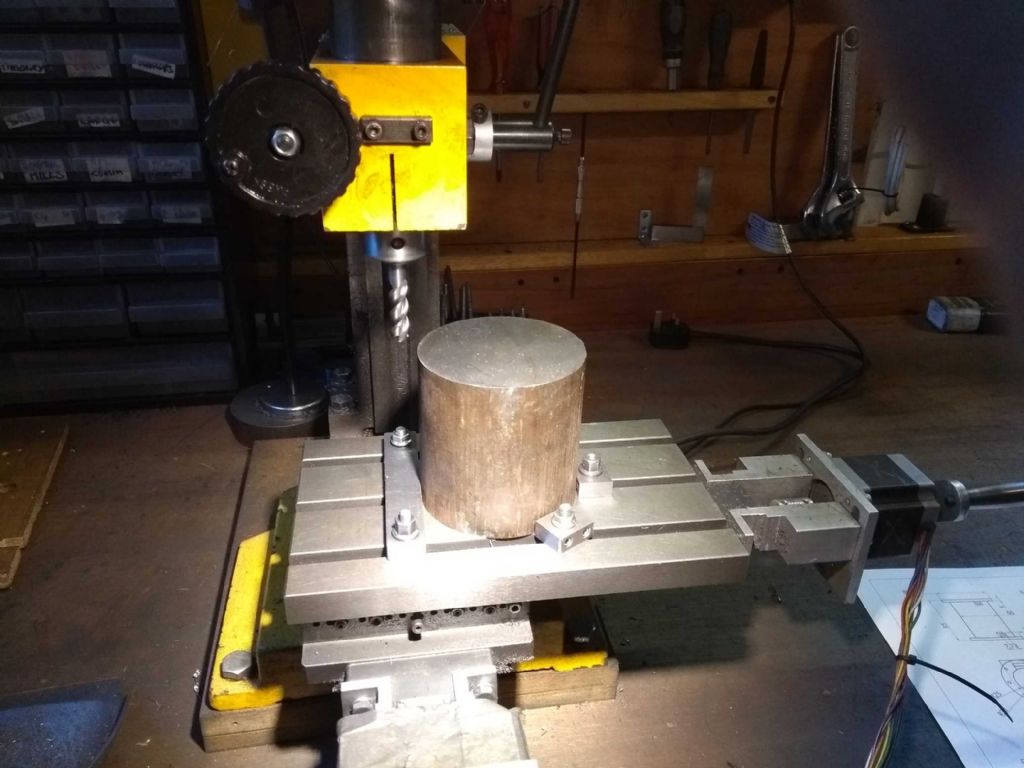
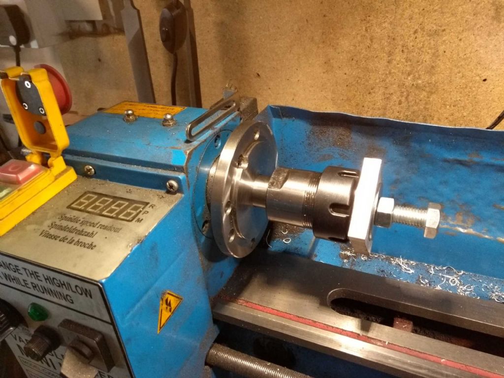
This gives and idea
The MT2 blank (drilled and tapped to M10 is held in by a 10mm bolt, the cylinder fits snugly on the spacer cylinder and another M10 bolt clamps the top of the cylinder – as below. As seems usual, I'd underestimated the spring in the boring bar and ended up cutting the inside a bit too much making it rattle somewhat. However, a 0.15 shim (feeler gauge) slipped around the blank fixed that nicely!
You can see why a normal chuck just wouldn't work!
Also in view is my Heath Robinson mill end stop. A couple of clamps bolted down and nice little vertical rod on the Y axis to act as a stop.
I said above that the other reason that I couldn't mount it on a chuck is the lack of grip. There is a LOT of vibration when removing the outside of the cylinder. The Z creeps up, the handles fall off and the X can shift too (so I need one hand to hold the X axis, one to hold the z axis and one to turn the wheel – hang on….!)
What's more challenging is that it's actually shifting the rotary table on the mill table, even after adding stops and clamps to it. In fact that's where I gave up today. I have to work out how to hold it in place more rigidly.
Or I could revert to taking very small cuts but this is already taking forever!
A mill and a rotary table will NEVER replace a lathe…
Iain
19 March 2019 at 21:19 #401295Iain Downs
Participant@iaindowns7829519 March 2019 at 21:31 #401301Gas_mantle.
Participant@gas_mantleHi Iain,
I have most of the materials and the flywheel casting so I'm committed to starting it soon but haven't yet finalised how I'm going to cut the cylinder and so haven't yet bought the stock for it.
Last year I made a little entablature engine using the technique Jason explained for the cylinder earlier in this thread. I thought I could just about squeeze a 60mm bore from an 85mm square with care but I may need to look again at the maths. The bore I'm aiming for is approx 60mm and about 80mm stroke but if it ends up at 55mm then that isn't a problem.
Peter
-
AuthorPosts
- Please log in to reply to this topic. Registering is free and easy using the links on the menu at the top of this page.
Latest Replies
Home › Forums › Stationary engines › Topics
-
- Topic
- Voices
- Posts
- Last Post
-
-
Pattern Makers Vice
Started by:
 Vic
in: The Tea Room
- 3
- 3
-
2 July 2025 at 02:08
 peak4
peak4
-
Motor won’t start
Started by:
Rowan Sylvester-Bradley in: Beginners questions
- 6
- 6
-
1 July 2025 at 23:52
noel shelley
-
Meddings MF4 Manual
Started by:
Richard Kirkman 1 in: Help and Assistance! (Offered or Wanted)
- 10
- 20
-
1 July 2025 at 23:42
JohnF
-
Speed camera
Started by:
 David George 1
in: The Tea Room
- 14
- 16
-
1 July 2025 at 23:25
Nigel Graham 2
-
J&S grinder – belt which way ?
Started by:
gerry madden in: Manual machine tools
- 5
- 6
-
1 July 2025 at 22:53
Chris Crew
-
IME Watchmakers lathe
Started by:
Greensands in: Manual machine tools
- 11
- 16
-
1 July 2025 at 21:41
Dave S
-
Request for a Slot to be Milled in a Shaft
Started by:
James Alford in: Help and Assistance! (Offered or Wanted)
- 9
- 18
-
1 July 2025 at 21:03
bernard towers
-
Bearing boxes for ball race
Started by:
Paul McDonough in: Beginners questions
- 9
- 17
-
1 July 2025 at 21:02
Paul McDonough
-
Twin Engineering’s heavy mill/drill quill removal
Started by:
Martin of Wick in: Manual machine tools
- 7
- 9
-
1 July 2025 at 20:51
Martin of Wick
-
The Stevenson Trophy – Entries Invited
Started by:
 Neil Wyatt
in: Website Announcements
- 1
- 2
-
1 July 2025 at 18:44
 Neil Wyatt
-
The Bradford Cup – Nominations Wanted
Started by:
 Neil Wyatt
in: Website Announcements
- 1
- 2
-
1 July 2025 at 18:41
 Neil Wyatt
-
FreeCAD v1.0 tutorials
1
2
3
Started by:
 Michael Gilligan
in: CAD – Technical drawing & design
- 12
- 54
-
1 July 2025 at 18:31
Speedy Builder5
-
Haining vertical dairy engine boiler.
Started by:
apprentice in: Beginners questions
- 2
- 2
-
1 July 2025 at 18:26
 JasonB
-
All things Beaver Mill
1
2
…
8
9
Started by:
Robert James 3 in: Manual machine tools
- 43
- 208
-
1 July 2025 at 18:22
Charles Lamont
-
Dial test indicator vs Dial indicator
Started by:
martian in: Workshop Tools and Tooling
- 17
- 24
-
1 July 2025 at 16:59
Clive Foster
-
Help for DIY lathe build.
1
2
Started by:
moogie in: Help and Assistance! (Offered or Wanted)
- 16
- 32
-
1 July 2025 at 15:21
David Senior
-
Firth Valve Gear
Started by:
Andy Stopford in: Traction engines
- 9
- 18
-
1 July 2025 at 12:59
Nigel Graham 2
-
M type top slide conversion??
Started by:
jimmyjaffa in: Beginners questions
- 7
- 11
-
1 July 2025 at 11:35
 David George 1
-
Offen screw type telescopic gauge.
Started by:
Graeme Seed in: Workshop Tools and Tooling
- 4
- 9
-
1 July 2025 at 10:41
Graeme Seed
-
2 Machine lights
Started by:
modeng2000 in: Workshop Tools and Tooling
- 2
- 6
-
1 July 2025 at 08:57
Dalboy
-
New member looking for help
Started by:
 manfromthemist
in: Introduce Yourself – New members start here!
- 11
- 24
-
1 July 2025 at 08:19
Juddy
-
Wiring up a single phase AC motor with 4 wires
Started by:
ell81 in: Beginners questions
- 6
- 8
-
30 June 2025 at 19:49
Howard Lewis
-
New (old!) member
Started by:
iansoady in: Introduce Yourself – New members start here!
- 3
- 3
-
30 June 2025 at 19:30
Howard Lewis
-
Boiler Design – issue 4765
1
2
…
7
8
Started by:
Charles Lamont in: Model Engineer & Workshop
- 26
- 178
-
30 June 2025 at 12:58
Paul Kemp
-
High strength 4mm steel?
1
2
Started by:
iansoady in: Materials
- 20
- 31
-
30 June 2025 at 10:55
JohnF
-
Pattern Makers Vice
-


