Steam Engine Governors

Advert

Steam Engine Governors

Home Forums Traction engines Steam Engine Governors

Viewing 25 posts - 26 through 50 (of 53 total)
  • Author
    Posts
  • #307534
    duncan webster 1
    Participant
      @duncanwebster1

      So do they control the steam valve by measuring the power output? I can see how that might work, but something somewhere must be controlling grid frequency.

      I'm sure Tubal Cain mentioned using butterfly valve for governor. There is no requirement for it to be steam tight, it only needs to close enough so that the engine doesn't race on no load. This would be balanced and a rotary gland rather than reciprocating, so might be less drag. If you're stuck with a doube beat valve, look at a basket seat, much less complicated coring. I have a very small diagram which I could scan if it would help

      Advert
      #307541
      JasonB
      Moderator
        @jasonb

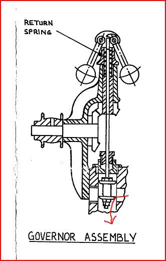
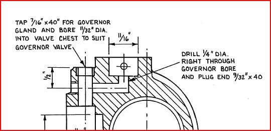
        The Fowler models get around teh coring issue by using a couple of drilled passages, one of which gets plugged with an iron plug.

        gov1.jpg

        gov2.jpg

        You may be lucky and be able to do something similar. It also suggests yhe valve bobbin is a "loose running fit" in the bore so not likely to seal completely but just stop the engine racing away.

        #307543
        JasonB
        Moderator
          @jasonb

          I just had a read through Julia's governor post on TT and it's interesting to see she had to go for thinner flat spring material to get the governor to work, quite interesting to see how the springs deflect in use.

          I know Andrew will be able to see the post but they do only show to members.

          One other thing I noticed while looking through Preston's governors for sale is that Pickering made them to suit various BSP pipe sizes. It would be interesting to compare the details of a large one and another about 1/3rd the size to see how they differ, I doubt they used exotics for the balls but more likely played with the size of ball and spring section.

          #307607
          duncan webster 1
          Participant
            @duncanwebster1

            Is there a hole up the centre of the bobbins to connect the top chamber to the bottom? If not it doesn't appear balanced. The chamber above the top valve bobbin would be full of steam at boiler pressure (by leakage past the bobbin), similarly the chamber between the 2 bobbins is at boiler pressure, but the pressure under the bottom bobbin is steamchest pressure which is lower. If there were a hole, all would be well, but it needs to be substantially bigger than the leakage area twixt bobbin and bore so there will be little pressure drop between top and bottom chambers. Subject to this it appears to have considerable potential.

            Edited By duncan webster on 17/07/2017 17:54:24

            #307611
            JasonB
            Moderator
              @jasonb

              No Hole. As the governor never really closes then there will always be steam above it and below.

              Why should the steam chest be at a lower pressure ? as soon as the regulator is opened you have an open passage from boiler to valve chest so all at boiler pressure.

              Edited By JasonB on 17/07/2017 18:28:08

              #307627
              Neil Wyatt
              Moderator
                @neilwyatt
                Posted by JasonB on 17/07/2017 18:18:51:

                Why should the steam chest be at a lower pressure ? as soon as the regulator is opened you have an open passage from boiler to valve chest so all at boiler pressure.

                If the pressure is the same between the two rings of the bobbin and outside them, then there's no point using a balanced valve instead of a plain one.

                I bet the full-size valve has a hole, it may not be critical on a small one.

                Neil

                #307640
                Anonymous

                  As I recall measurements by "Julia" and "suctionhose" on TT showed that the steam chest pressure is lower than boiler pressure, sometimes by a considerable amount. Inevitably heat is lost through the cylinder block, and since the steam isn't normally superheated the pressure will drop. If there is a flow of steam there will be a pressure drop along the passageways. And if there is a throttling valve there could be isenthalpic expansion.

                  Looking at the discussion of full size valves on TT the advice given is to have a few thou clearance when cold. Since the bronze/gunmetal expands faster than cast iron when hot the clearances will decrease. So I don't think one can say that steam pressures will be the same on both sides of a sleeve valve. The governor will have limited force to apply to the valve. My engines are running at 170psi, the same as the full size engine. So even allowing for a significant drop from boiler pressure and a smaller valve the force created by unequal pressures could be tens of pounds. I'll have to do the sums, but my gut feel is that the governor isn't going to generate those sort of forces in the valve spindle.

                  Andrew

                  #307643
                  duncan webster 1
                  Participant
                    @duncanwebster1

                    If there isn't a pressure drop across the governor valve it isn't doing anything and might as well not be there. Granted when the engine is flat out you don't want any pressure drop, that's why you design it so that the valve is fully open at some small % below no load speed and fully shut at some (probably even smaller) % above.

                    This only applies to throttle governing, proper engines use cut off governing.

                    Edited By duncan webster on 17/07/2017 22:02:37

                    #307654
                    Anonymous

                      There are some good ideas on balanced valves here; thanks Jason. Duncan, yes I would be interested in seeing a scan of the basket seat, if only because I can't visualise it.

                      I looked at the TT thread by "Julia"; the cylinder block is designed to take a screw in valve seat, pretty much as per full size. Sadly I simply don't have room in my cylinder block for one. Nor is there room for the simpler method of the Fowler drawings. There is only 1/16" between the vertical valve hole and the steam chest, and the steam passage breaks into the steam chest all by itself. At least according to the drawings. I'll have to revisit my 3D CAD model of the cylinder block as my model came out rather differently to the drawings. And on the evidence so far the drawings will be wrong.

                      I can't move the governor either, even though the pulley on the governor and crankshaft don't line up. The advice some while back on TT was to ignore it, and the drive belt will be fine. Apparently the pulleys don't line up on the full size SCC either. So at least if they're misaligned that's one in the eye for the rivet counters when they smugly point it out.

                      My current thinking is that I'm stuck (not literally I hope) with a sleeve valve. However, I plan to drill holes in the top, so at least the space above the valve, where the spindle gland is located, is at something like the same pressure as the main steam passage. Of course the issue of leakage from the spindle gland then arises. Interestingly in the drawings of full size double beat valves the full steam passage pressure is present at the gland too. I have seen on the 'net a photo of a Garrett governor valve. It's basically an upside down tin with a spider instead of a solid 'base' that screws onto the spindle. That's what I plan to emulate.

                      As to the problem of the leaky gland, I suspect that a cold drawn stainless steel spindle and reamed hole won't quite be good enough. So I plan to redesign the gland to take a PTFE inner core. Virgin PTFE is 'orrid stuff to machine, and creeps like a Dickensian character. At least in this case if the drilled/reamed hole closes slightly it'll be an advantage. And it is low friction.

                      I need to sit down and do some basic sums, starting with determining whether the steam passage as drawn is large enough to run the engine.

                      Andrew

                      #307685
                      JasonB
                      Moderator
                        @jasonb

                        Thanks Andrew, I'll see if I can find Ross's (Suctionhose) readings, I was going by Julia's readings going up Engine Hill where she was only showing a drop of a few Psi from her 160psi boiler pressure with the engine working hard but not flat out speed wise.

                        #307706
                        Anonymous
                          Posted by JasonB on 18/07/2017 08:22:13:

                          Thanks Andrew, I'll see if I can find Ross's (Suctionhose) readings, I was going by Julia's readings going up Engine Hill where she was only showing a drop of a few Psi from her 160psi boiler pressure with the engine working hard but not flat out speed wise.

                          I'll modify my statement slightly. The steam chest pressure will be lower than boiler pressure, but when everything is wide open, I'd expect the drop to be less than when the steam is being throttled.

                          Andrew

                          #307708
                          Anonymous
                            Posted by duncan webster on 17/07/2017 22:01:36:

                            This only applies to throttle governing, proper engines use cut off governing.

                            Bother, all that effort and it turns out I'm not building a 'proper' engine; lost enthusiasm now. sad

                            Andrew

                            #307712
                            Howard Lewis
                            Participant
                              @howardlewis46836

                              Almost all governors require a drop in speed (droop) to initiate action to recover the loss of speed. As the speed decreases, in a Mechanical governor, the force of the governor spring overcomes the centrifugal force acting on the weights, and as the weights fall, the linkage attempts to increase engine power, to regain the the lost speed..

                              Hence in this case, as the saw starts to cut, load on the engine increases, speed falls, and the governor admits more steam to counteract this, so that the exhaust note hardens. You will hear the same thing happen with an Internal Combustion Engine, and the exhaust system will grow hotter, sometimes to the point of glowing red hot.

                              For A C power generation, especially where parallelling to the mains is required, speed has to be controlled much more closely, to maintain the correct frequency. When gensets are to be operated in parallel,, it is usual for one set to be designated as the master, which is isochronously governed, so that despite changes in load , its speed remains constant. The Woodward PSG was a servo governor which could provide variable droop, until it became isochronous, (it produced, internally, a false droop signal). In some samples, because of tolerance build ups, it was possible take the adjuster over centre, so that the speed would fall as the load was reduced!

                              The Stanadyne DB series of fuel injection pumps could also be fitted with variable droop governors, for power generation, or other applications where close control speed control was imperative.

                              Because the reel speed needs to be closely controlled, Combine Harvesters have tighter governing than Tractors, which because of power take off work, is again, tighter than for road vehicles. Close governing on a road vehicle can be unpleasant, as anyone who has experienced the governor cutting in on a Gardner powered vehicle, or an early diesel Land Rover, will testify!

                              Electronic governors operate by monitoring frequency, either internally, or that of the current being supplied to the load. Because of their almost instantaneous response, speed can be controlled extremely closely; sometimes to tenths of an R P M!

                              Howard

                              #307783
                              duncan webster 1
                              Participant
                                @duncanwebster1
                                Posted by Andrew Johnston on 18/07/2017 10:40:15:

                                Posted by duncan webster on 17/07/2017 22:01:36:

                                This only applies to throttle governing, proper engines use cut off governing.

                                Bother, all that effort and it turns out I'm not building a 'proper' engine; lost enthusiasm now. sad

                                Andrew

                                By proper I mean 1000hp plus, I'll let you get away with throttle governing on a traction engine. I can't find the diagram of basket seat, so I've done a hand drawing and scanned it. Basically steam can get past the top seat then out through the holes in the side of the tubular bit of the seat, it can also pass down the centre of the bobbin, then do a 180 degree turn past the bottom seat and out through the holes again. The bottom plate of the seat is solid, just has a guide bush for the bobbin. The bobbin has a spider to connect the outer bit to the bit which fixes to the spindle. The downside is that for a given flow area the valve has to be a lot bigger diameter than one where steam is fed to the undersifde without going through the bobbin.

                                basket seat_20170718_0001.jpg

                                #308171
                                Anonymous

                                  Thanks for the diagram. It's unfortunate that the way my cylinder block is designed there simply isn't any room for proper balanced valves, of any sort, and the associated valve seats.

                                  Andrew

                                  #308208
                                  Anonymous

                                    Here are my calculations on the steam flows in the cylinder block. Clearly I've made a series of assumptions, which are probably pessimistic in practise, but the intention is to get order of magnitude answers as to whether the engine will be choked by inadequate steam supply.

                                    Although the engine is a compound we only need to consider the HP cylinder. I'm not going to worry about the case of the simpling valve being open. The HP bore is 2", stroke is 3.75", and I have assumed 500rpm as a maximum. Although I haven't designed the valve gear yet I think that a maximum cutoff of 75% is reasonable.

                                    So the maximum volume of steam per revolution is:

                                    2 x pi x r² x stroke x cutoff

                                    The volume is times 2 because the engine is double acting. I make the answer:

                                    17.67in³

                                    and per minute, times the maximum rpm:

                                    8835.7in³/min

                                    The steam passage to the valve chest is 9/16" diameter, so how long would a 9/16" diameter cylinder be for one minutes worth of steam? Basically the volume of steam divided by the area of the steam pipe. I make that:

                                    35555in or 2963ft

                                    So to provide the necessary volume of steam said steam will need to be travelling at 2983ft/min, aka 33mph.

                                    That's quite a conservative value compared to the 5000ft/min recommended by some older textbooks, and modern steam engineering recommends even faster flows. Presumably because that gives smaller pipes, equals cheaper to install.

                                    So on the basis of the above calculations it seems that the engine is unlikely to be choked with a 9/16" diameter supply area. I just need to make sure that the same area is maintained, or exceeded, through the rather complex steam passages in the cylinder block. The passages are under my control as there are no cored passages in the block as supplied.

                                    Andrew

                                    #308217
                                    Anonymous

                                      Warning – despite being imperial in the previous post, I'm now going mostly metric, just to show even handedness.

                                      Another factor is consider is the type of flow, laminar or turbulent? Why does this matter? If I understand the theory correctly laminar flow in pipes tends to lead to a pressure drop proportional to velocity. But for turbulent flow the pressure drop is proportional to the square root of the velocity, so should be lower all other things being equal.

                                      My engines will run at a maximum pressure of 170psi gauge, and at that pressure the speed of sound in steam is 505m/s. My calculated speed above translates to 15.05m/s. That is well below the speed of sound, so the steam flow can be treated as non-compressible, which simplifies the equations.

                                      To determine the type of flow we need to calculate the Reynolds number. This is a dimensionless number, basically the ratio between inertial forces and viscous forces. It is defined by:

                                      Re = (p x u x D)/µ

                                      p is the density, for steam at 170psi it is 6.48kg/m³

                                      u is the velocity, 2963ft/min equals 15.05m/s

                                      D is the diameter, 9/16" equals 0.0143m

                                      µ is the dynamic viscosity in Pa.s, for steam at 170psi it is 1.539×10^-5 Pa.s

                                      Putting all that together we get a value for the Reynolds number of:

                                      90616

                                      This is well into the turbulent regime. The transition from laminar to turbulent flow occurs for Reynolds numbers in the mid to high thousands.

                                      So all is well, or course the above could just be a load of nonsense. Of course the only thing that really matters is how the engine performs.

                                      Andrew

                                      #308226
                                      duncan webster 1
                                      Participant
                                        @duncanwebster1

                                        For short passageways the pressure lost by friction against the walls is likely to be low, what is of more importance is pressure lost going round bends, through changes of section etc. This is dependant on the velocity squared.

                                        is called the head, which working in SI has units of metres, multiply by density and you get pressure in Pascals. Every fitting, bend, change of section etc has an associated head loss coefficient, a sharp bend is 0.5 (depending on what you call sharp!), so in your case we have

                                        velocity V=15.05

                                        density ρ = 6.48 kg/m^3

                                        g = 9.81 m/sec^2

                                        head = (15.05^2*6.48)/(2*9.81) = 75 Pa

                                        which is about 0.01 psi, which I wouldn’t get too worried about.

                                        #308365
                                        Anonymous
                                          Posted by duncan webster on 22/07/2017 12:37:45:

                                          which is about 0.01 psi, which I wouldn’t get too worried about.

                                          Quite so! The steam passage from boiler to steam chest is quite convoluted. Although my drawings are by LSM the cylinder castings are to the original Filby design, where the steam passages are a combination of drilled holes and slots machined into the outside of the thick (3/8" ) liners. The best I can do is ensure that the cross-sectional area remains fairly constant and try and reduce any sharp corners or edges. My gut feel is that heat loss is going to be more important than pressure drops due to the flow.

                                          Andrew

                                          #308482
                                          Martin Johnson 1
                                          Participant
                                            @martinjohnson1

                                            Hello all,

                                            I have only just come across this post, but hope I can shed a bit of light.

                                            First, the theory, Imagine a graph of governor opening up the left and speed across to the right. To govern you must have a curve that falls from left to right. To get isochronous governing, you need a curve that is a vertical line at the desired speed. In practice the best we ever get is a very steep slope – even on electricity generation work. As Andrew has derived in his post of 15/7 you need to get the springs and masses right, otherwise you can get instability (hunting), when the curves described above on the opening / speed graph become a Z shape.

                                            In practical terms, for a given mass of balls (bit like this post) you need the correct spring RATE. Changing pre load will change the set speed, but does nothing about stability or instability. You will also appreciate that to get some degree of governing with a modest speed variation is in theory achievable, but to get good governing you are trying to create that very steep curve, while avoiding creating a Z curve.

                                            Everything that has been said about increasing forces by increasing rotational speed, and ball mass is correct and will give more actuating force.

                                            The Filby design is dire, in that the governor is expected to move a cylindrical plug with 160 psi pushing it to one side – think if the stiction! On the 4" Burrell SCC, I managed to work in a scheme of drillings to achieve what Duncan has sketched above. I then very carefully made a wee bronze cage loctited into the block and a stainless bobbin,. After many years of further work, I was able to see if it would restrict speed. Under "no load", it didn't.

                                            After 10 years of running the model, the governor drive pulley always has a load of oil on it – so I concluded that trying to drive a governor with a flat leather belt was probably a non starter.

                                            Taking those two factors into account, my enthusiasm for working governors rather died. However, I have the world's only model of a Burrell Patent Dustproof governor – but without the internals completed. I then decided to build a 7" scale steam lorry, but that is another story………….

                                            If you can do it, Andrew, I will be the first to applaud, but please don't get trapped down that avenue – I want to see your two engines in steam – governor or not!

                                            All the Best,

                                            Martin

                                            #308669
                                            Anonymous

                                              Thanks for the reponse Martin. It's helped clarify some points and given me practical help.

                                              I think I now understand the relationship between the balls and leaf springs. Initially the springs look complicated, but I think they can be broken down into simple cantilevers. Each spring is constrained by the ball and being clamped at the ends. So as the ball moves out the spring bends more towards the axis of rotation. But at some point the bend reverses as the spring is constrained at the outer end. At the point of reversal I think the bending moment and stresses are zero. So we can treat each half of the spring as two independent cantilever springs. So it should then be simple to do the calculations to come up with a thickess for the leaves, depending upon the material chosen.

                                              One thing I'm not sure about is total movement of the control valve. If I've understood some of the posts on TT correctly the valve should be able to move from fully open to fully closed. At fully open you can get full power, if required. If something breaks on the governor then the valve needs to close to prevent unloaded run away. I think this is a facility not provided on my model governor, as the sleeve valve will be open with the balls at rest.

                                              I'm not sure how much oooph the speed controlling spring needs to provide. It needs to resist the movement of the spindle, but presumably not by much. On the other hand it needs to be able to overcome any friction in the spindle so that when the governor slows down it can push the spindle upwards. Note: the spindle is pushed down as the balls move out via a ball acting as a thrust bearing, but there is nothing to pull the spindle back when the balls slow down, except the torsion spring. And of course steam pressure as designed.

                                              My control theory is a bit rusty, alythough I am familar with the s-plane and the role of poles and zeros from filter theory. Maxwell showed that the response of the governor is dependent upon the roots of a second order polynomial. I'd guess that two complex conjugate poles would give a better frequency response than a single real pole. For stability the poles need to be on the left hand side of the imaginary jw axis. I'd wing the maths and say that an isochronous governor has the poles on the imaginary axis. I think that hunting is a different problem to stability, caused by friction in the case of a mechnical governor. In control theory a time delay can cause instability, due to a reduced phase margin, but I don't think this is the same as friction in a mechanical system.

                                              Obviously I need to think a bit harder about the valve arrangement. I might even be able to eliminate the pulley offsets if I move the governor!

                                              I'll try not to get bogged down. I'd like to get the engines running before I kick the bucket!

                                              Andrew

                                              #308689
                                              Martin Johnson 1
                                              Participant
                                                @martinjohnson1

                                                Hi Andrew,

                                                I agree with your proposal to analyse the leaf springs as 4 back to back cantilevers. To give you some more design flexibility, some of the original Pickerings had laminated leaves – I have seen up to 3. The earlier photo in this thread just about shows it. (I think!)

                                                On the theory side, I think there are 2 cases to consider – steady state and time dependant. My description dealt with steady state – it is quite possible to end up with an inherently unstable governor if the change in Wr2 on the balls exceeds the change in force on the spring(s). Hence the attention needed to spring rate. Note no friction is considered in this analysis, but friction will make the situation worse.

                                                It is also possible to get time dependant instability due to rapid changes in load, or periodic fluctuations in load coinciding with the natural response frequency of the governor system. I would suggest this is likely to be less of a problem in a steam engine model, where things happen relatively slowly. Remember the originals were built to cope with sawbenches and threshing machines – and quite a lot of skill in feeding both was required.

                                                I also think there is an inherent problem with the sliding plug valve on the Filby design. It needs to move quite a lot to control, whereas the twin seat balanced valve is "fully open" at 1/4 of the seat diameter – I make that about 18% of the sliding plug travel (1/root 2 divided by 4) for a given passage. Having said that, unless the boiler pressure is way down, I very rarely have to open the regulator more than 1/4 travel, so it might be possible.

                                                Have you made the cylinder blocks? If not, I will try and dig out what I did by way of wangling a caged valve into the design.

                                                Best Wishes,

                                                Martin

                                                #308823
                                                Howard Lewis
                                                Participant
                                                  @howardlewis46836

                                                  Stability, or otherwise is function of the time constant of the governor versus the rate of acceleration of the machine being controlled.

                                                  At C A V, the governor team were caused most concern by Diesel engines that had a high rate of acceleration. The most difficult could accelerate at 5,000 rpm/second. Conversely, a Governor with a very small time constant can cause problems. I've seen ones trying to react to, and control, torsional vibrations!

                                                  A full scale steam engine would accelerate much more slowly. (But probably still too quickly for peace of mind with a run away!) Models may be different because the pressures and areas ( = forces) will be smaller, but the masses needing to be accelerated will be smaller to compensate. So the problems, such as friction in the governor linkage causing instability will still be there.

                                                  As already said, Preload sets the speed, Spring Rate determines the slope of the governor curve, and if too steep will cause instability. Hunting is caused by too steep a governor run out curve..

                                                  Surging is likely to be caused by friction making the time constant of the Governor too long, (The standard BBC bus sound effect; a London Transport RT surging, can often be cured by adjusting the buffer stop on the injection pump to damp out excessive movement of the control rod)

                                                  As Scotty used to say, "Y'canna scale Physics"

                                                  Howard

                                                  #309547
                                                  Anonymous

                                                    Thanks for the replies, more things to think about!

                                                    I recall from discussions on TT that some full size governors had multiple leaves, usually three but sometimes five. Presumably this gave an additional variable to play with to 'tune' the governor if needed.

                                                    Ah, yes the smaller movement of the balanced valve makes sense now in terms of the control movements needed.

                                                    Martin: No I haven't machined my cylinder blocks yet. I'm itching to get on with them as most of the features such as cylinder and valve rod locations seem to agree with the drawings, for once! Even if I did get rid of the 1% tilt on the cylinder block. I would be most interested to see what you did in getting a balanced valve in place. Did it involve moving the governor? If so that may help with the pulley misalignment.

                                                    One thing seems odd about the governor control loop. The valve has one, and only one, position for each associated speed as the balls and valve position are tied together mechanically. This isn't normally the case where valve position can be moved independent of speed measurement. I assume that's why the Pickering governor causes a speed change as a result of load change. Whereas a governor which has independent valve movement can correct exactly for a speed change initially created by a load change.

                                                    Slightly to my surprise I've got my length of tungsten rod from China via Ebay. So I now need to do some trials to see how easy it is to machine.

                                                    Andrew

                                                    #309556
                                                    duncan webster 1
                                                    Participant
                                                      @duncanwebster1

                                                      All mechanical governors have a speed change when the load varies, the difficult bit is to minimise it without inducing hunting. One of the best was the Lumb governor **LINK**

                                                      Even that had a speed change of ~3% from full load to no load. If anyone manages to make a working model of one I'll buy him/her a pint! (That is after it's been written up for ME)

                                                    Viewing 25 posts - 26 through 50 (of 53 total)
                                                    • Please log in to reply to this topic. Registering is free and easy using the links on the menu at the top of this page.

                                                    Advert

                                                    Latest Replies

                                                    Home Forums Traction engines Topics

                                                    Viewing 25 topics - 1 through 25 (of 25 total)
                                                    Viewing 25 topics - 1 through 25 (of 25 total)

                                                    View full reply list.

                                                    Advert

                                                    Newsletter Sign-up