Steam Canoe Machinery

Advert

Steam Canoe Machinery

Viewing 17 posts - 51 through 67 (of 67 total)
  • Author
    Posts
  • #591633
    JasonB
    Moderator
      @jasonb

      There was certainly a car part used on them but not sure what. Probably hard to come by now.

      Advert
      #591640
      John Olsen
      Participant
        @johnolsen79199

        Are the Stuart pumps driven directly off the crosshead, eg at engine speed? If they are, I would suggest not using that design. The best pump arrangements I have seen on small steam boats use a reduction drive to drive the pumps at about 1/3 to 1/4 engine speed. The merit of this is that engine speed pumps are very noisy. Reduction drives can be toothed belt or gear, the toothed belt is quieter but may offend the purists. (So hide it in a casing.) Actually a worm drive would also be possible, the feed pump for the model Stuart double 10 uses one.

        Dancer has lever operated engine speed pumps as per the original Leak design, once I figure out how to fit a reduced speed setup into the extremely limited space available they are going to be replaced. The original arrangement might be more true to full size design, but engine speed pumps are VERY NOISY! Sorry about shouting but you probably would not be able to hear me over the noise of those ******* pumps.

        It is a bit of a problem, most of us like the idea of a slow turning engine with gleaming parts that you can see going around, but the reality of getting power from small engines is that they need to turn quite fast. Reciprocating pumps, on the other hand, do not like being driven fast.

        But on the other hand, the engine you have acquired looks like just the thing.

        John

        #591658
        JasonB
        Moderator
          @jasonb

          John. they are lever operated from an enclosed gearbox, not sure of ratio but looks like the reduction you mention would fit, there is also the boiler feed pump and an oil pump

          #591671
          Howard Lewis
          Participant
            @howardlewis46836

            The AC-Delco fuel lift pumps used on I C engines were usually driven by a simple eccentric on the camshaft, so often running at up to 3000 strokes per minute.

            Obviously designed for use with fluids, such as kerosene, petrol or gas oil. Operated dry, the valves emitted a "creaking" sound, but quietened when primed, and pumping liquid.

            The usual delivery pressure was rarely more than 5 psi, with a limited suction lift.

            The eccentric driven operating lever merely pulled down the diaphragm to fill the pump. The internal spring actually provided the delivery pressure.

            The valves would not seal so effectively with a non liquid. The pumps always worked much better once they had primed with fuel.

            The lever shape and length were determined by the distance of the mounting flange from the centreline of the camshaft.

            I have seen one used on a chop saw to pump soluble oil. (The diaphragm had failed, so we bodged it by making a replacement out of two pieces of polythene sheet Where needs must etc! )

            That was easy, because the top and bottom castings were held together by short setscrews, and we drilled and tapped the operating ting rod to clamp the new "Diaphragm" to it under the top washer.

            Service kits, containing a new diaphragm and valves, used to be available.

            The later ones were not intended to be serviceable, The setscrews and tappings were replaced by a rolled steel band.tom hold upper and lower halves together.

            Having said that, we would probably make up two semi circular bands with a suitable internal profile and use screws and tappings to replace the rolled steel clamp.. The problem then would be obtaining the replacement diaphragm and valves.

            The pipe tappings, certainly on the later units, (60s onwards ) were 1/2 UNF.

            Pipe to pump sealing was usually by a metal compression olive, although during the 80s, one engine manufacturer changed to using rubber olives, compressed by the pipe nuts as they screwed into the pump body.

            HTH

            Howard

            #591673
            JasonB
            Moderator
              @jasonb

              This video of Gil's Swan shows the setup quiet well.

              #591680
              noel shelley
              Participant
                @noelshelley55608

                Interesting use of a stuart hand boiler feed pump as a lube oil pump with a ratchet drive on the swan. The two vacuum pumps do look like an adapted AC fuel pump ? Noel

                #591984
                Peter Cuthbert 1
                Participant
                  @petercuthbert1

                  Hi Everybody

                  Thank you all so much for all your posts. I am sorry to have been 'silent' but lack of Internet connectivity tends to be handicapping. Hopefully I will get that issue securely nailed this week.

                  Having done a little more research it is clear that one would run this engine in a boat at probably 600-800 RPM rather than the 200-300 one expects with larger engined boats. As John has said at that speed cross head driven pumps would be a horrible noise. The 1/4 engine speed suggestion sounds much more civilised.

                  Thanks also for the video of the Swan engine. I particularly liked the idea of a single eccentric driving two horizontally opposed pumps in 2CV fashion. That looks the sort of design that should not be too difficult to implement. I am somewhat puzzled about the function of the two domed items which do indeed look like fuel pumps from the 1960s but how do they relate to the two conventional cylinder pumps below? As you can see I still have loads of ignorance that needs to be removed. I probably need to see some drawings. The Cygnet came with small drawings for the main engine and another for the reversing gear. That does rather support the points made earlier about the pumps being an optional extra. Oddly the purchase also included some photocopied drawings of the ST steam feed pump. That seems to be a horizontal affair in the fashion of Weir pumps and has a lot of castings. I have never seen those offered so it must be another piece of ST history. I must ask the vendor why they were included.

                  Best wishes

                  Pete

                  #591993
                  noel shelley
                  Participant
                    @noelshelley55608

                    Top 2 pumps act as vacuum pumps the 2 below are feed water pumps ! and a stuart hand pump has been used as a lube oil pump ! Weir type feed water pumps can be difficult to make and even more difficult to get to work. ST do/did offer a set of castings for this type of pump, i have one sitting here. Noel.

                    Edited By noel shelley on 29/03/2022 22:26:50

                    #591994
                    John Olsen
                    Participant
                      @johnolsen79199

                      There would normally be two boiler feed pumps, and if the engine is to be condensing, one *vacuum pump. The two water pumps gives you a backup if one fails, and also allows bringing up the level a bit faster if you use both at once. There is no law against having more than one vacuum pump, so maybe that is what they did. It has to have sufficient capacity to remove all the air and condensate from the system, and maybe if they were using a commercial item one wasn't quite enough.

                      * No doubt someone will get all pedantic on me, some people don't like calling it a vacuum pump, claiming that the vacuum is created by the condensation of the steam into water. Actually there would never be a vacuum in the condenser if the pump didn't pump all the air and condensate out, and vacuum pump is less of a mouthful to say than air and water pump. Of course it is never a true vacuum, but then nothing ever is, not even in deep space.

                      John

                      #592012
                      JasonB
                      Moderator
                        @jasonb

                        The Cygnet used one pump and the Swan doubled everything up as there were two cylinders not one.

                        They are diaphragm not piston pumps hence the relatively large dia compared to height.

                        Couple of photos of the Cygnet setup here as well as a description

                        #592015
                        SillyOldDuffer
                        Moderator
                          @sillyoldduffer

                          Posted by John Olsen on 29/03/2022 22:23:51:

                          …* No doubt someone will get all pedantic on me, some people don't like calling it a vacuum pump, claiming that the vacuum is created by the condensation of the steam into water. Actually there would never be a vacuum in the condenser if the pump didn't pump all the air and condensate out, and vacuum pump is less of a mouthful to say than air and water pump. …

                          John

                          Being pedantic about engineering descriptions should be forbidden by law, because engineering nomenclature is pretty random plus English instantly adopts foreign words and expressions whenever they add value. Nothing British about carburettor or program!

                          James Watt called the device in question an Air Pump and he invented it, which is good enough for me!

                          Seems JW had the idea of a separate condenser first and found his prototype gradually stopped working due to air in the steam building up and severely weakening the vacuum. So he added a mechanical pump to forcefully remove air and condensed water, job done.

                          Pedantically, I don't believe the Air Pump does much more than keep air pressure from rising above atmospheric inside the condenser: it's condensing steam that creates most of the vacuum that gets more power out of the engine.

                          Dave

                          #592050
                          Nigel Graham 2
                          Participant
                            @nigelgraham2

                            Either I have missed it or no-one has mentioned it, but there is a very simple and obvious reason why those Stuart engines have directly-driven pumps that don't work very well at power-boat racing revs.

                            They replicate full-size marine engines that rarely exceeded 100rpm, and were usually a good bit slower.* We can't expect simply magnifying the speed to make the miniature machinery work as well as its prototypes did.

                            I wondered how this affects other miniatures.

                            It surprises me that the directly-driven feed-pumps on miniature traction-engines and steam-wagons work at full speed – efficiently at least. Many full-size overtype steam wagons engines were designed to run up to 400rpm, sometimes higher, but I think the pump drives were usually geared down. Some may have had delivery air-chambers to cushion the hammer-blow effects.

                            Locos? Scale for 5" g is 11.3:1. So scale for 60mph = 5.31 real mph, = 0.09miles/min. That makes a 7" dia driving-wheel twirl round at ~ 254rpm: dragging the poor little axle-driven feed-pump along with it. I believe some railways and competitions impose an 8 real mph limit – for 5" gauge that represents a heady 90mph; with the power-plant itself moving at about 380rpm.

                            —-

                            *W.S. Hutton, The Practical Engineer's Handbook; Crosby, Lockwood & Son, 1911

                            #592053
                            JasonB
                            Moderator
                              @jasonb

                              They are not replicas and don't have directly driven pumps, they run via a gearbox. Stuarts sold them as being suitable for powering small watercraft hence they give power figures and size of hull they may suit. You could not fit a larger engine and associated larger boiler into a small steam canoe or launch.

                              This is why they are usually short stroke and referred to as high speed marine engines rather than long stroke mill types or those found on much larger vessels

                              regarding traction engines only a few had geared down pumps such as the GMT, good model designer will adjust throw of the eccentric and ram size so it performs better at higher revs though in most cases the injector would be used and the pump just left with the bypass open

                              Model powerboats of the time would be running flash steam and at far higher revs that even the 1000rpm design speed of the Swan. My Bassett Lowke will happily do 2500rpm and that is just a small basic pond boat engine.


                              Edited By JasonB on 30/03/2022 13:10:49

                              #592116
                              Peter Cuthbert 1
                              Participant
                                @petercuthbert1

                                Hi Folks

                                Many thanks for the latest updates. Thanks Noel for the explanation of the drawings for the horizontal feed pump. I wonder if the Cygnet vendor originally got a set of Cygnet castings minus the pumps and added a horizontal feed pump as being more 'authentic'. I use that word very cautiously as it could be that the vendor was a ships engineer and having a history of Weir style pumps wanted one, or perhaps he did not like the look of the 'Mushroom' set up of the Cygnet pumps pair. I think I would fall into the latter category if it was a choice facing me. I must get around to ringing hm up and finding answers to all these questions.

                                Thanks for explanations about the Cygnet vacuum/air pumps. It did dawn on me eventually that the two cylinder Swan was a doubling up of everything on the Cygnet including pumps. A good idea to standardize on existing castings as it would mean not having extra castings that might not sell.

                                There is a good video if one wishes to see the Cygnet running to be found here [https://www.youtube.com/watch?v=-u6FQytLOh4] It provides some very close up views of the pump arrangement with the reduction gear box, the water pump and its auxiliary bits and bobs. My comment about a 2CV style set up was me thinking about how one could implement a feed pump and a reciprocating vacuum pump. Why not have them horizontally opposed running from the same eccentric? That ought to be space efficient and possibly weight efficient too both of which will be needed for the canoe. I shall have to fire up the CAD package and see what I can draw.

                                It should not be too difficult to size the water pump since it is possible to work out how much steam is used at (say) 500 RPM and work that back into litres/gallons that need to be pumped plus a little extra to cope with losses from the whistle use, etc. However, I must make enquiries about the coil boiler used in a fellow SBA member's canoe. I seem to recall that he said that he runs it with a very high water throughput getting wet steam and thus avoiding cyclinder lubrication. However that is from memory so I may have the wrong end of the stick.

                                So thanks everybody. It looks as if my next task is to start looking at boilers and then go back to the feed pump design and also think about condensing, or not.

                                Best wishes

                                Pete

                                #592132
                                John Olsen
                                Participant
                                  @johnolsen79199

                                  To take the last point first, you probably should think about condensing, if not as part of the initial installation, at least as something you will want to add. Otherwise you have to plan on carrying as much water as you might need, or else on filling up from over the side with water of possibly dubious quality. A keel condenser is probably the simplest way to go. A surface condenser will require a circulating pump, eg another thing to go wrong. My plant actually has a surface condenser, luckily I was able to find a nice gear pump for the circulating pump which has the merits of being very simple, no valves, very quiet and absorbs very little power. But there is still much to be said for the keel condenser, the main downside being the prospect of damaging it while grounding or trailering the boat.

                                  Sizing water pumps is not necessarily all that easy, I followed the drawings and found that in practice I needed to increase the size of the pump rams. As it stands now, I can keep the boiler at a steady level with just one pump running. The Weir pump might have been someone being cautious, it is nice to have plenty of backup to get water in the boiler if you have a coal fire. Not so bad with my oil fired setup, where at the flick of a switch I can take the heat away, if the water level got too low.

                                  It's not Stuart that had the engine speed pumps, my Leak does although as mentioned above, they are scheduled to go as soon as I figure out how to fit things in. Some other designs do to.

                                  One feature of the Cygnet design that I would question is the location of the air pumps, high up. This suggests that they are going to have to lift the condensate from the condenser in most cases, where people use a keel condenser. If you are lifting the condensate through a foot, you are losing an inch of vacuum. So keep the pump low, close to the condenser.

                                  The tendency towards the end of the original steam launch era was to go to shorter strokes and higher rpm. This has the merit of reducing the required prop size, allowing it to fit into a smaller cutout in the hull, and also reducing the required draft. The engine becomes more compact too. A smaller prop at higher speed has lower efficiency, so it is all a bit of a tradeoff.

                                  John

                                  #592279
                                  Peter Cuthbert 1
                                  Participant
                                    @petercuthbert1

                                    Hi John

                                    Many thanks for the post and words of wisdom. I had been thinking a bit about condensing though from an idleness point of view. If set up properly it should keep the boiler water level spot on without the need to faff. However, my reluctance at the moment is, as ever, from ignorance. The plan for this canoe hull is to have splitable into two or perhaps three pieces. The designers do that with some of their other designs so will show me what is needed if I go that way. I'm not sure how I would get a condenser to go with that. The reasoning behind splitting is to do with weight, space and age. Whilst I try to keep fit, as a small old bloke the amount I can lift is limited so the canoe in two or three parts is at most 20kg per bit. The engine and pumps should be below 20kg and removable. The coil boiler is also under that limit if I get the one I am thinking about built. The space issue is essentially to do with winter storage which will be the mezzanine 'shelf' in the garage which is not big. Transport is also an issue and a trailer is out of the question as there is nowhere to keep it. Thus all the bits must go inside the VW and leave room for passengers.

                                    Happily I am now in the position where I have the plans for the canoe, the boiler and now the engine, though minus the pumps. What is needed is to find the time to pull all the pieces together and see that they will all fit. I'm not sure when that will get done as there seems to be so much going on here. This is a badly built 1930s house and seems to be in permanent need of being 'fixed'.

                                    Going back to the pumps issue, I quite like the idea of fitting a 1:4 gearing on the rear shaft of the engine which will put the bigger gear directly below the small gear. That can drive a single eccentric which can activate the two pumps that will be horizontal and effectively down by the bottom of the engine base level. That fits well with your observation.

                                    All the information I have been collecting about the Cygnet suggests that 500-600 RPM would be a normal working speed so I need to go back to my propeller calculations and see what the higher speed produces. I suspect that will be a much smaller prop which will fit in better than the original proposal.

                                    Regards

                                    Pete

                                    Edited By Peter Cuthbert 1 on 31/03/2022 21:46:35

                                    #616155
                                    Peter Cuthbert 1
                                    Participant
                                      @petercuthbert1

                                      Hi Model Engineering Friends

                                      I thought it was time to provide a brief update on this project. Much has come in the way of it including Solar PV with battery, much fighting with our electricity retailer, much work on the improvement of the rear garden, particularly in relation to Builder Shame dating from since the time the house was built rigt up to thelast time we had builders on site, adding the mezzanine floor to the garage, and trying to find door and window suppliers capable of installing kit that is pushing the latest building regs. On the hobby side I have worked with long time steam canoe and mono-tube boiler enthusiast John Emmett on a couple of articles on mono-tubes for the SBA's Funnel magazine. With those done it seemed a good idea to create a website to bring together all kinds of mono-tube steam generator information/views from anybody who is willing to contribute. Having used Concrete CMS before I volunteered to do the basic set up work, but found I had got the latest version (v9) which is quite different to the version with which I was familiar. Steep learning curve time. Anyway the framework and some material is there now and contributions will be welcome: https://www.mono-tube.org.uk

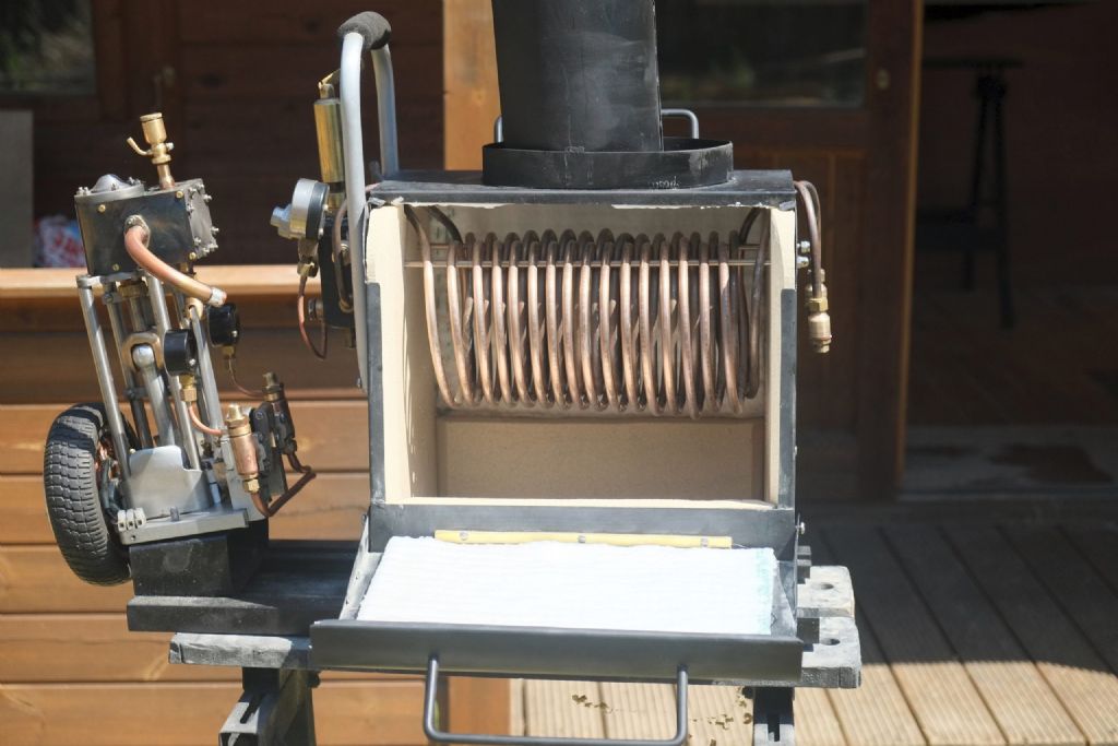
                                      Having worked with John I am now of a mind to copy his mono-tube steam plant in Snipe but using the existing Cygnet. As work on that starts I will keep you posted. A picture below:

                                      Best wishes

                                      Pete

                                      je boiler & engine.jpeg

                                    Viewing 17 posts - 51 through 67 (of 67 total)
                                    • Please log in to reply to this topic. Registering is free and easy using the links on the menu at the top of this page.

                                    Advert

                                    Latest Replies

                                    Viewing 25 topics - 1 through 25 (of 25 total)
                                    Viewing 25 topics - 1 through 25 (of 25 total)

                                    View full reply list.

                                    Advert

                                    Newsletter Sign-up