Stated thread depth never works for me.

Advert

Stated thread depth never works for me.

Home Forums Beginners questions Stated thread depth never works for me.

Viewing 18 posts - 26 through 43 (of 43 total)
  • Author
    Posts
  • #654929
    Chris Crew
    Participant
      @chriscrew66644

      I have only just skimmed through this post, so if someone has already mentioned what follows, I apologise. But for all the technical thread dimensions provided and talk of the set-over top-slide method I could not see any mention that the 27.5deg. or 30deg. set-over should be to the transverse axis of the lathe, not the longitudinal. It may be in there somewhere but I couldn't see it, if it is I am not trawling through all the answers again to find it.

      This is a common error that a beginner could make and would account for an incorrect depth of thread. Also, you do not need to do any trigonometry to obtain the additional in-feed required, the lathe can do this for you. So, set-over the top-slide to required half angle of thread form to the transverse axis of the lathe with the tool at 90deg. to the work as set with a screw-cutting gauge.

      With the tip of the tool just touching the work, zero both cross-slide and top-slide dials. Move the saddle to the right until the tool is just clear of the work and put the full depth of thread on with the cross-slide handle and then zero the cross-slide dial again. Withdraw the tool just clear of the work with the top-slide and proceed to screw-cut putting the cuts on with the top-slide and withdrawing from the cut with the cross-slide hand-wheel as normal and returning it to zero to start the next pass with the cut put on with the top-slide. When the top-slide dial reads zero the correct depth of thread has been achieved as the tool has been fed in along the hypotenuse formed by the rear flank of the thread. If the nut is a little tight, advance the cross-slide a thou. or two and take a finishing cut. This will ease the thread which will be quite good enough for all practical purposes because we are not making a micrometer.

      This is how I was trained to screw-cut and it works every time for me. BTW, if you are cutting an internal thread you can still use this method by simply inverting the tool and cutting the thread on the rear of the bore. This also has the advantage that you don't have to think about which way to withdraw the tool at the end of the cut, it is exactly the same as in cutting an external thread and you can also see what is happening in the bore as the cuts progress.

      Sorry, I forgot to mention that the work should be supported by a tail-stock half-centre if at all possible, and a travelling steady on particularly long work-pieces, because there will always be some deflection which will affect the depth of cut in slender work. Where this is not possible, make a couple of additional passes without altering the finished depth setting. This will 'work out the spring' in the work. I know this is common knowledge to the old hands but it may not be so obvious to a beginner.

      Edited By Chris Crew on 02/08/2023 23:38:36

      Edited By Chris Crew on 02/08/2023 23:40:31

      Advert
      #654932
      Chris Crew
      Participant
        @chriscrew66644

        Sorry, I am not going to keep re-editing the preceding post ad-infinitum as things come to mind but another advantage of the set-over top-slide method is that the tool does not have to be ground to exactly the thread angle. As long as the cutting edge is set at the correct flank angle to the screw-cutting gauge it doesn't matter what the rear face is as long it is not greater than the included angle of the thread. Therefore, you can grind a top and side rake angle on the tool to make it cut more freely in steel.

        #654945
        Jim Gardner
        Participant
          @jimgardner97734

          Firstly, thank you all for the comprehensive answers. Secondly, sorry for asking as I seem to have opened a can of worms.

          The good news is that at 10pm last night, after 3 attempts, I finally had a left hand thread, 1/2 inch Whitworth bolt. The bad news is, it took 3 attempts and to 10pm.

          I can see (thank you Jason for the drawings) how different profile inserts make a difference to thread depth. What I cant understand is 1. Why manufacturers don't publish some type of chart or equation for applying to thread cutting. 2. How anyone copes with the trial and error method I used. Making a bolt is not a 5 minute job. 3.Why a full form/profile cutter would need to take any material off the top of the crest. A 1/2" bolt had an OD of 0.500". A 1/4" bolt has an OD of 0.250" etc. Surely it is what it is. Why would we need to make that OD less?

          Lastly. It seems many people make a female first (in this case we can say a nut). If I made a LH thread 1/2" W nut to use as a gauge for the LH 1/2" W bolt I am making, how would I ever know how deep to cut the threads in the nut, in the same way I can't determine how deep to cut the bolt?

          I intend to ring the very helpful suppliers today and ask them if there is a get around for this.

          As with so many things in life, the more I learn, the more I realize how little I know.

          Thanks again.

          #654946
          JasonB
          Moderator
            @jasonb

            It does not reduce the OD. If you look at that first image I posted of the Whit thread form you should be able to see the crests of the threads are rounded not pointed but the top of those crests measure 1/2"

            This rounding of crests that the full form inserts give is a good indication that you have fed in the correct distance, if there is a flat you have not gone in enough if you keep feeding after the inserts starts reducing the OD you have fed in too far

            As for a get around you just need to measure with thread wires and note the infeed for a given tpi then next time you come to cut that same tpi you will know how deep to go. Or do the calculation, sketch in CAD etc as posted earlier

            #654947
            Nigel Graham 2
            Participant
              @nigelgraham2

              Yes, a thread should be to the stated diameter but unless you can finish it to the correct profile – with full-form tool, chaser or die- it will have a very sharp V-crest. The reduction is no more than about 0.002" radius, to leave a tiny flat.

              For most practical purposes that tiny reduction in contact area is insignificant: tables of tapping-drill sizes can give tapped holes with a much greater truncation, in proportion, than that shaving off a turned thread..

              #654949
              Howard Lewis
              Participant
                @howardlewis46836

                As Apprentices, we were taught that Unified threads were f truncated. The simple method was to turn the work JUST undersize. Somewhere, I've got the handout with the formula for how much.

                Similarly, internal threads would have slightly oversize bore, so that root / crest interference did not happen.

                Anyone disagreeing with this should take it up with a certain aero engine firm, based in Derby.

                So pesumably it worked satisfactorily when they made cars and oil engines.

                Howard

                #654950
                Anonymous

                  Screw threads are far more complex than most people realise.

                  1. Manufacturers sell to commercial machine shops who have the knowledge to work it out. They are not interested in the tiny amateur market.

                  2. I use full form inserts, topslide parallel to the lathe axis, and a calculated depth of cut. Once done I check with mating part, if it doesn't fit take a couple of thou off the diameter and repeat as needed. For multiple parts once the initial thread is cut there is a number on the cross slide dial to hit, plus a sanity check that the mating part fits.

                  3. The full form inserts shape the crest and remove fine burrs produced by the screw cutting. Commercial screw threads are made to published tolerance grades all of which have ODs slightly less than nominal. I've just measured the OD of a commercial 1/4" BSF set screw, which is 0.245", ie, 5 thou under.

                  Professional machine shops use a similar trial and errror method, but they use precision ground go/nogo thread gauges for checking.

                  Andrew

                  #654956
                  JasonB
                  Moderator
                    @jasonb

                    As I said easy enough to work out how much more infeed is likely to be needed for partial form inserts that will get you quite close.

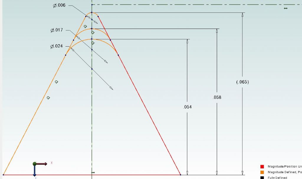
                    insert infeed.jpg

                    A quick look at an insert manufacturers catalogue gives the tip radii of full and partial forms.

                    A full form 12tpi whit insert has a 0.012" radius (0.024dia) and stated infeed of 0.054"

                    A G55 partial insert which covers 14-8tpi has a 0.0085" radius ( 0.017" dia) but no infeed given but from the above you can see it would need an infeed of 0.058" to get a similar flank measurement

                    An AG55 Partial insert has a tip radius of 0.003" (.006dia) again no infeed but from image needs an infeed of 0.065"

                    So depending on which partial form insert you have feed in to those numbers, thread may still seem a bit tight so a file running along the crests may be all that is needed to get it to fit. Flex in the machine, spring passes etc will all affect final fit so can't always just go by numbers 


                    Edited By JasonB on 03/08/2023 08:59:16

                    #654958
                    Martin Kyte
                    Participant
                      @martinkyte99762
                      Posted by Chris Crew on 02/08/2023 23:59:52:

                      Sorry, I am not going to keep re-editing the preceding post ad-infinitum as things come to mind but another advantage of the set-over top-slide method is that the tool does not have to be ground to exactly the thread angle. As long as the cutting edge is set at the correct flank angle to the screw-cutting gauge it doesn't matter what the rear face is as long it is not greater than the included angle of the thread. Therefore, you can grind a top and side rake angle on the tool to make it cut more freely in steel.

                      Which is why I said don’t bother when using partial form inserts.
                      regards Martin

                      #654961
                      not done it yet
                      Participant
                        @notdoneityet

                        Secondly, sorry for asking as I seem to have opened a can of worms.

                        No need to apologise and no can of worms at all – just another ‘compromise’ explained. Nothing more than cutting gears with the eight different cutters in a set – each cutter (should) only really fit one tooth count, the rest being ‘OK’ but still a compromise – series production (think commercial gearboxes, etc) would never use a ‘compromise’ cutter.

                        Little different than most hobby mills cutting ‘conventionally’ whereas a commercial mill would employ ‘climb’ milling – because they can – as it is the better option if possible.

                        #654973
                        Tony Pratt 1
                        Participant
                          @tonypratt1
                          Posted by Chris Crew on 02/08/2023 23:59:52:

                          Sorry, I am not going to keep re-editing the preceding post ad-infinitum as things come to mind but another advantage of the set-over top-slide method is that the tool does not have to be ground to exactly the thread angle. As long as the cutting edge is set at the correct flank angle to the screw-cutting gauge it doesn't matter what the rear face is as long it is not greater than the included angle of the thread. Therefore, you can grind a top and side rake angle on the tool to make it cut more freely in steel.

                          Hmm, bit of a sweeping statement, so a screw cutting tool of say 30 degrees included angle would be ok in your view? Full disclosure, I used to use the set over method but now use full form inserts.

                          Tony

                          #654977
                          Martin Connelly
                          Participant
                            @martinconnelly55370

                            Joe Pie did a video on the idea that a single point thread cutting tool does not need the correct angle on the second face. Worth a look.

                            Martin C

                            #654998
                            Chris Crew
                            Participant
                              @chriscrew66644

                              "Hmm, bit of a sweeping statement, so a screw cutting tool of say 30 degrees included angle would be ok in your view?"

                              Yes, it would, because the rear flank is formed by the advance of the tool, the rear edge of which performs no cutting action whatsoever which is why you can grind top and side rake on it. The accuracy of the included angle is clearly dependent on the accuracy of the set-over and the setting of the leading/cutting edge of the tool. But in any event, we are talking about making a bolt or a stud here in an amateur's lathe in a back-shed workshop, not producing high precision threads for a scientific or measuring instrument, so a degree or two adrift is negligible. I know some people on here may like us to think that they work to Rolls-Royce or NPL standards, and I take my hat off to them if they can because there is obviously nothing wrong in striving for accuracy, but my skills only allow me to do a bit of 'metal bashing' in the shed at the bottom of the garden. It all works for me, at least most of the time!

                              Edited By Chris Crew on 03/08/2023 14:08:52

                              #655002
                              Jim Gardner
                              Participant
                                @jimgardner97734

                                Chris,

                                You're exactly right in that I am making a one off bolt and I will probably never have to make another one again, and I am doing it on a Colchester Bantam.

                                It is very rare that I ever have to make two of any threaded part (of the same dimensions) so buying a die or tap, go/no go gauges etc for every part I have ever made would be astronomically expensive. The same applies to full profile inserts for every thread/pitch I have ever, or will ever, cut.

                                This is why I purchased partial profile inserts, assuming (perhaps wrongly) that a Zeus book / Machinery handbook or the web would give me some way of working out how to get required depth etc using a PP insert of *** radius. Obviously I know there is more to it than that but I'm sure you get the idea.

                                #655003
                                duncan webster 1
                                Participant
                                  @duncanwebster1
                                  Posted by Nigel Graham 2 on 03/08/2023 08:06:58:

                                  Yes, a thread should be to the stated diameter but unless you can finish it to the correct profile – with full-form tool, chaser or die- it will have a very sharp V-crest. The reduction is no more than about 0.002" radius, to leave a tiny flat

                                  No it won't, it will leave a flat. For metric threads this is as specified, but Whitworth are rounded. That's when you attack it with a file.

                                  #655006
                                  Nigel Graham 2
                                  Participant
                                    @nigelgraham2

                                    Sorry, I should have been clearer. Radius of the bar, not of the thread crest. I said it leaves a flat.

                                    #655008
                                    Nigel McBurney 1
                                    Participant
                                      @nigelmcburney1

                                      Most of my screw cutting is done with top slide parallel to the bed,and using HSS machine type thread chasers, on Myford and Colchester lathes, works ok on most materials..if I i feed in to the specified thread depth i find the thread is either tight on the nut or will not fit.I just put this down to minor deflection of the lathe slides and toolholder. its most noticeable on steel water pipe,which is one of the worst steels to machine of the commonly used materials,as its water pipe I usually machine the od a little smaller than specified dia, just to save abit of tool wear,with pipe of say 3/4 to 2 inch nominal dia I find that the thead is always over size and deeper cut have to be taken,I dont get worried or concerned ,and just get on with it.It would be more worrying if screwcutting cut undersize. I tend to use chasers as I did an awful lot of thread cutting as an instrument maker on Lorch and similar bar chasing lathes,When industry got in a bad way over 30 years ago there was a lot of redundant cutting tools from dealers so I bought a lot of chasers as job lots. I now have thread water pipe when restoring tank cooled stationary engines to get the cooling water pipes installed plus the exhaust pipes. When threading large dia pip which will not pass through my lathe mandrels, I securely clamp the pipe to the cross slide and fit a die in its holder into the lathe chuck and produce threads that was which is similar to a commercial pipe threader. another advantage of this method is that long lengths can be threade by removing the tailstock.

                                      #655121
                                      larry phelan 1
                                      Participant
                                        @larryphelan1

                                        I think Sparey mentions this problem on page 161 of his book.

                                        I came across something similar a while ago while making nuts for a friends trailer.

                                        I removed one of the other nuts, made a screw to match it, and then used that to test the new nuts.

                                        Worked out well.

                                      Viewing 18 posts - 26 through 43 (of 43 total)
                                      • Please log in to reply to this topic. Registering is free and easy using the links on the menu at the top of this page.

                                      Advert

                                      Latest Replies

                                      Home Forums Beginners questions Topics

                                      Viewing 25 topics - 1 through 25 (of 25 total)
                                      Viewing 25 topics - 1 through 25 (of 25 total)

                                      View full reply list.

                                      Advert

                                      Newsletter Sign-up