Posted by Michael Gilligan on 25/06/2021 21:35:57:
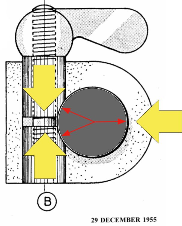
As promised, Martin : Here’s my version of the clamping geometry
… with the bar shown smaller diameter, for clarity.
Assume that the bar is ‘grounded’
- Tightening the clamp screw moves the two pads
- That in turn moves the whole block sideways
- Clamping then takes place at three lines [running into the page] with locations roughly indicated by the tips of the red arrows.
- Because the clamp radius and the bore in the block are [in reality very slightly] larger than the bar radius, there can be no other contact … it’s just those three lines.
With appropriate dimensions; these movements, and the clearances created, will be small : but they do say “a miss is as good as a mile”
MichaelG.
.

Edited By Michael Gilligan on 25/06/2021 21:38:42
Hi Michael
I don't disagree with what you say and when the pad bolts are machined in situe when the main bore is bored then the arrangement will be pretty much as you describe. However even when machined as just stated there must be some clearance in the pad bolt bore itself and tightening the bolt may well move the line if contact quite possibly inwards.
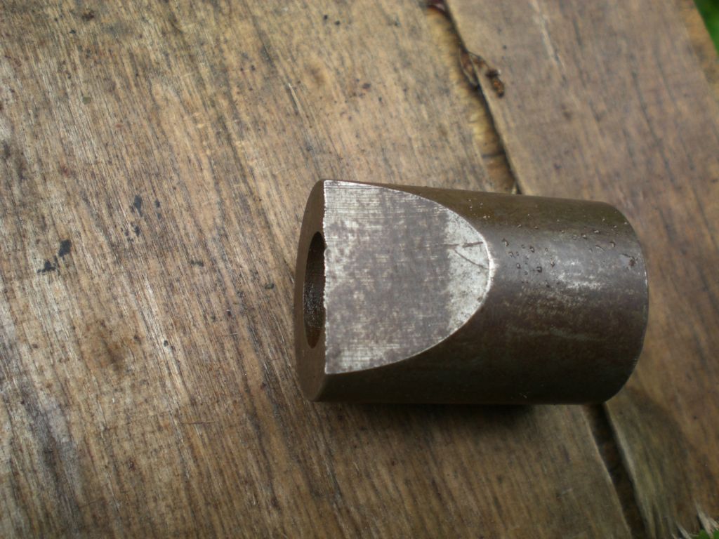
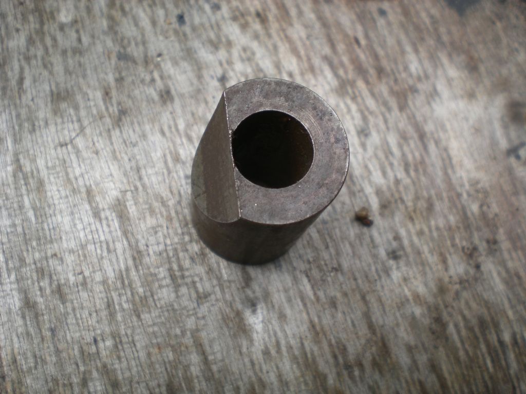
To return to the situation of the OP that of the front bar of the Quorn it is impractical to machine in situe and a fixture is made to generate the pads seperately. In fact it cannot be guarenteed that the offset of the pad bore to the main bore in the fixture is exactly the same as that in the finished clamping system. In consequence the actual relationship of the curve on the pads may not be absolutely concentric with the main bar and it is anyones guess where the contact line will actually end up when fitted.
Taking the above statement to be the case. We should design for worst case which is when the line of contact is at the inner most end of the pad as this is the point of shallowest taper. Therefore if we use Duncan's formula of G = D/8 wherever the line of contact ends up there can be no wedging action and the cotter will always self release.
As I said I agree with your analysis for a perfect assembly, but even in that case parts wear and the wear on the pad will tend to eventually conform it to the radius of the main bar whereby your slightly larger radius on the pad disappears and contact is possible towards the inner ends of the pads. I'll ignore flexibility and material compression.
In practice locking is encountered at times. I have made a number of pad bolts and it can happen. My initial post was intended to show that offset was there just to allow clearence for the bolt and had nothing to do with the clamping action. This got us onto what does matter to clamping and to the subsequent debate.
So my conclusion is that whilst lockup will not normally happen if the system is made perfectly as you describe and is in an unworn condition, to ensure that it can never happen when that is not the case, having a Gap equal to one eigth of the main bar diameter is good practice, especially when the pads have not been machined in situe in the first instance.
regards Martin
Edited By Martin Kyte on 26/06/2021 11:15:07
ChrisLH.


