Spilt line for direction of TE crankshaft bearings

Advert

Spilt line for direction of TE crankshaft bearings

Home Forums Traction engines Spilt line for direction of TE crankshaft bearings

Viewing 12 posts - 1 through 12 (of 12 total)
  • Author
    Posts
  • #2939
    Mark Simpson 1
    Participant
      @marksimpson1

      Need a sanity check!

      Advert
      #479425
      Mark Simpson 1
      Participant
        @marksimpson1

        I'm (slowly) building 6" Little Samson. and have just cleaned up the bronze castings to make the Main Crankshaft bearings. They are cleaned up, split and soldering back together… Then my dilemma – When installed does the split line sit horizontally or vertically? can't find it on any drawings or photos, please enlighten me!

        Thanks in advance
        Mark

        #479428
        Anonymous

          Crankshaft bearings are split horizontally. Otherwise it would be difficult to assemble the engine.

          Andrew

          #479430
          Mark Simpson 1
          Participant
            @marksimpson1

            Thanks Andrew, I guessed that would be the case, just wanted to check before final machining… The outer shells become rectangular by 1/8" so there is no going back once I take the next step.
            your gear cutting exploits are a real lesson in how to do things properly – a tour de force.

            #479433
            Paul Kemp
            Participant
              @paulkemp46892

              Split line on the LS is vertical. Bearing adjustment is via the horizontal bolts that go in the front of the housings. Yes it's a bitch to assemble as the crank needs dropping in with the bearings on it, needing several hands! I am sure it is shown on the drawings but I can't remember where off hand.

              Paul.

              #479452
              Anonymous

                Bother, when I was posting I had a premonition that I was going to end up looking a wally. And so it came to pass. embarrassed

                Andrew

                #479463
                Paul Kemp
                Participant
                  @paulkemp46892

                  Andrew, there are always exceptions to the rules. I don't know the sense of it, I guess that's how the full size were. Would have made more sense to me to make them round, Avelling style in 3 parts with filing strips and have the adjustment done with the caps but maybe there were patent issues back in the day! The one sense of the vertical split is most of the wear is likely to be in the horizontal plane – which is where the adjustment is on the LS.

                  Mark, You are correct, I have just checked the drawings and they don't show it, might be in Edward's book though if you have it. If you can get on Traction Talk there are a few build threads running on there both past and present for the LS in various scales from 3" to 6" (including mine) one good one to view is Stovepipe in Ireland loads of pictures and videos on that one with machining set ups and views of completed assemblies for inspiration. You mention gears – I cut mine but be aware it's a boring job if you have not done it before! I did mine on the H/ V Omnimill but to do the largest pair I had to do them horizontal on the table and feed by raising the knee. If you don't have a large machine where you can benefit from the powered axis it would be worth rigging up a power feed, otherwise it's a lot of handle winding!

                  Paul.

                  #479464
                  Paul Lousick
                  Participant
                    @paullousick59116

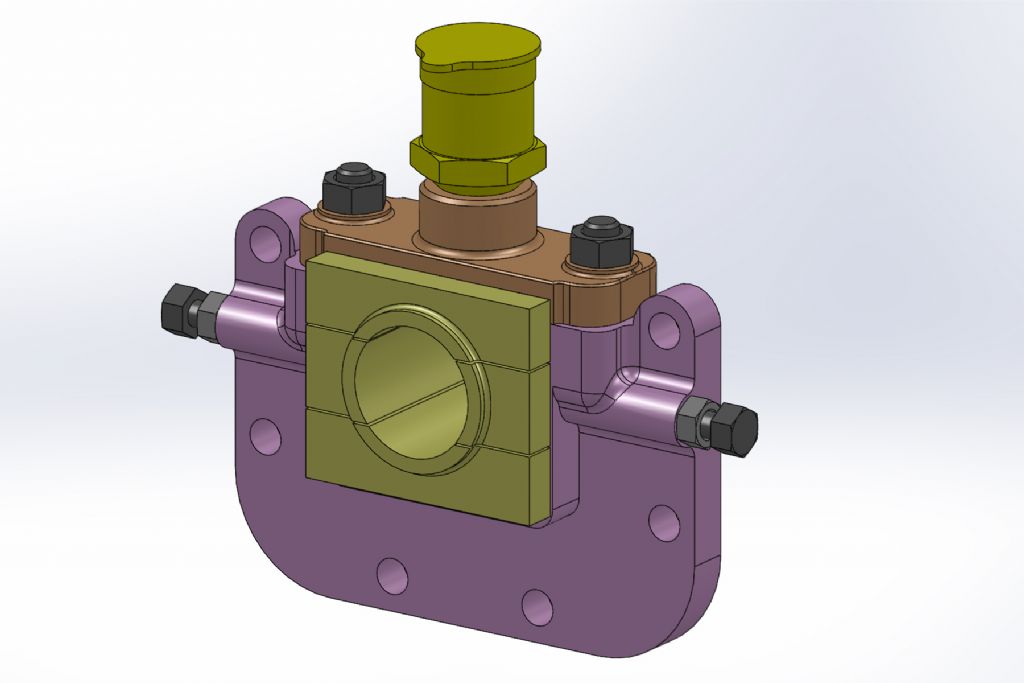
                    The crankshaft bearings on my Ruston are split horizontally. And are adjusted horizontally by the 2 screws on the side and vertically by shims under the retainer plate at the top.

                    Paul.

                    6-rp-07 crankshaft bearing assy.jpg

                    #479487
                    Mark Simpson 1
                    Participant
                      @marksimpson1

                      Thank you Andrew, Paul L and Paul K.

                      Paul L. that's just a better arrangement.

                      Paul K. thanks for the domain info, I searched the drawings and Dave Millway's build book without success; kind of glad you could not find it either (at least I was not man looking). With there being a bolt on strap at the top and the horizontal adjustment screw I lost the plot…. I guess the crank becomes more out of alignment as things wear; the brackets are not handed so the screws adjust in opposite directions! when the time comes I will be reaching for the shims i guess.

                      I've done my gears, using a home brew horizontal attachment with the Right Angle head on my KRV3000 (bridgeport clone on steroids). The smaller ones using a dividing head, the larger three using a 15" rotary table and a lot of handle winding; steady work but very rigid in that setup.

                      Off to the workshop

                      Thanks
                      Mark

                      #479489
                      JasonB
                      Moderator
                        @jasonb

                        "the brackets are not handed so the screws adjust in opposite directions!"

                        As the Little Samson has one bracket inside the hornplates and the other outside you should end up with both screws facing the same way


                        Fowlers used a similar arrangement to Paul's drawing but the horizontal screw was just at the front and the bearings in 3 pieces. However the 2" & 3" MJ Eng designs just split it horizontally and use the cap for adjustment.

                        Edited By JasonB on 13/06/2020 08:06:08

                        #479597
                        Paul Kemp
                        Participant
                          @paulkemp46892

                          I suspect the full size may have been multi part bearings rather than just 2, similar as Paul shows for the Ruston but there are none left to look at! Shimming under the cap won't be a problem if you have split yours horizontally and it will be easier to assemble for sure! Bearings on my 4" Ruston are horizontally split 2 piece without any fore and aft bolts and they have been fine, that's done a lot of miles now.

                          As Jason says the adjusting bolts both face front. If you have not machined the brackets yet there is a small trap in the spacing of the retaining bolts to the horn. If they are put on a regular PCD as suggested by the drawings the bolt under the adjuster bolt boss goes through the edge of the boss. Most seem to move the position of that bolt down slightly easy spotted if you put the holes in the bearing bracket first and then drill through the horns. If you marked the holes on the horn and tried the reverse there would be tears!

                          Paul.

                          #481456
                          Mark Simpson 1
                          Participant
                            @marksimpson1

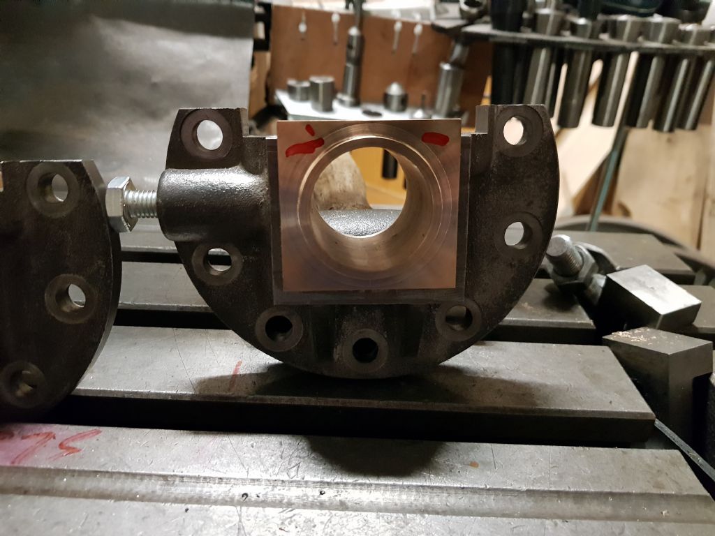
                            With a little care, and a lot of turning of the rotate table handle I've made the bearing from Edward's castings. Just need to add the studs and that's another piece tocked off the "to do" list

                            Paul. I also worked out that the holes were not possible to the dims on the drawing, so I respaced them having faffed around in CAD for a while to get some better looking positions.

                            20200622_133634.jpg

                          Viewing 12 posts - 1 through 12 (of 12 total)
                          • Please log in to reply to this topic. Registering is free and easy using the links on the menu at the top of this page.

                          Advert

                          Latest Replies

                          Home Forums Traction engines Topics

                          Viewing 25 topics - 1 through 25 (of 25 total)
                          Viewing 25 topics - 1 through 25 (of 25 total)

                          View full reply list.

                          Advert

                          Newsletter Sign-up