speed control pcb for Clarke CL300 lathe

Advert

speed control pcb for Clarke CL300 lathe

Home Forums Manual machine tools speed control pcb for Clarke CL300 lathe

Viewing 25 posts - 126 through 150 (of 226 total)
  • Author
    Posts
  • #84638
    Jon Harrison 2
    Participant
      @jonharrison2

      Hello again

      I’m just wondering if my CL300m has the same speed control pot issues as discussed here.

      Was fine 2 weeks ago then went to switch on last week and

      delay in starting 4-5 seconds instead of <1

      Slow rotation for about 1/4 turn of know and no further improvement.

      Very slow rpm, guess 20-40

      Edited By Jon Harrison 2 on 13/02/2012 15:31:55

      Advert
      #95179
      kelvin wright
      Participant
        @kelvinwright81290

        Hi Guys

        Super forum this, i need help too thou lol

        I have replaced both my 2SK790s and both my opto's due to my lathe running only at full speed.

        Thing is i can vary the speed from fast down a little bit but not much, i have tried to set the thing up using the preset as described in thisforum (R15 and R12) but they dont seem to do anything.

        Can any one advise please?

        Have checked all diodes, bridge and various resistors and all appears ok

        Thanks in advance

        Kelvin

        #95834
        kelvin wright
        Participant
          @kelvinwright81290

          Hi Folks

          Although no one replied to my post, I just thought i would say, that using some of the useful posts on here I was able to effect a repair and now have a fully working lathe.

          Special thanks to “John swift 1” for providing a excellent schematic, without which I am sue I would have been stuck, Thanks John

          Kelvin

          #95836
          kelvin wright
          Participant
            @kelvinwright81290
            Posted by kelvin wright on 06/08/2012 01:17:17:

            Hi Folks

            Although no one replied to my post, I just thought i would say, that using some of the useful posts on here I was able to effect a repair and now have a fully working lathe.

            Special thanks to “John swift 1” for providing a excellent schematic, without which I am sure I would have been stuck, Thanks John

            Kelvin

            #95843
            john swift 1
            Participant
              @johnswift1

              Hi Kelvin ,

              I'm glad you managed to fix the problem

              I've had a look back at my e-mails for the 26th and 27th july but it looks like no e-mail alert to your first post had been sent !! hence no reply

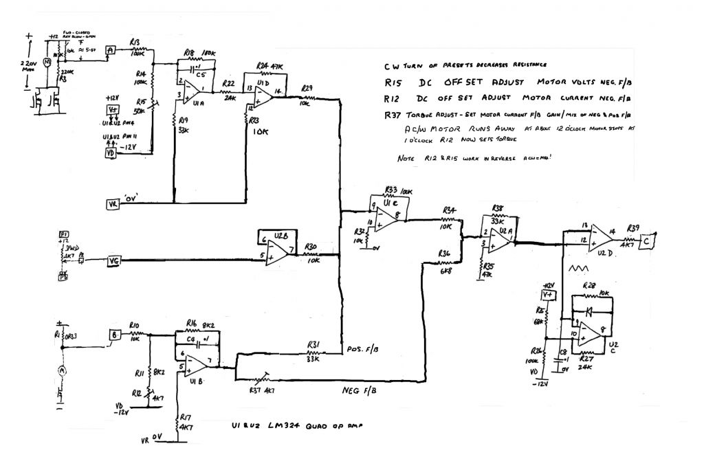
              as you may of found , in addition to short circuited FET's etc another reason for the board to give you uncontrolled full speed is the 220K resistor "R3" going open circuit or high resistance

              the resistor connects the negative motor terminal 1 to the control circuit input "A"

              R2 and R3 form the potential divider that sets fraction of the armature voltage thats compared with the 0 to 12V control voltage from the 4K7 speed control potentiometer terminal P2

              John

              #95985
              kelvin wright
              Participant
                @kelvinwright81290

                Edited By kelvin wright on 09/08/2012 00:39:59

                #96079
                kelvin wright
                Participant
                  @kelvinwright81290
                  Posted by john swift 1 on 06/08/2012 10:42:37:

                  Hi Kelvin ,

                  I'm glad you managed to fix the problem

                  I've had a look back at my e-mails for the 26th and 27th july but it looks like no e-mail alert to your first post had been sent !! hence no reply

                  as you may of found , in addition to short circuited FET's etc another reason for the board to give you uncontrolled full speed is the 220K resistor "R3" going open circuit or high resistance

                  the resistor connects the negative motor terminal 1 to the control circuit input "A"

                  R2 and R3 form the potential divider that sets fraction of the armature voltage thats compared with the 0 to 12V control voltage from the 4K7 speed control potentiometer terminal P2

                  John


                  Hi John

                  I sent you a message did you get it?

                  Cheers

                  Kelvin

                  #96088
                  john swift 1
                  Participant
                    @johnswift1

                    Hi Kelin ,

                    yes I received the messages sent yesterday but I looks like you didn't receive the alert to the reply !

                    John


                    message status at 13 14.jpg


                    Message Viewer


                    on the original speed control boards

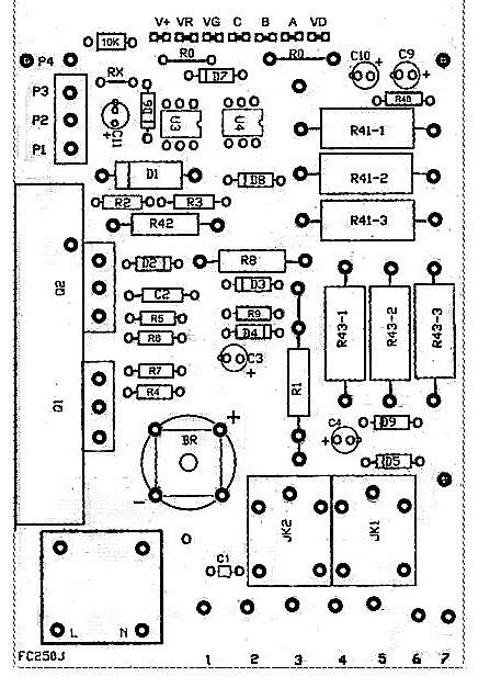
                    points A and B are two of the seven labelled connections
                    between the main PCB and the small PCB with the 2 dual in line IC's and preset potentiometers etc

                    if you have the later SMT version using the surface mount IC's you don't have the connections labelled

                    point B is the end of the resistor R1 (0.33 ohm on the 240v version ) connected to the motor via one of the relays and the voltage at this point is used to measure the motor current

                    point A is connected to junction of resistors R2 and R3 and is also connected to the terminal P4 via a 10K resistor

                    the voltage at point A is a measure of the motor armature voltage

                    when the forward motor direction is selected the 10K resistor is connected in parallel with R2 reducing the volt drop across R2 ( terminal P1 and point A )

                    as a result speed control circuit increases the armature voltage to re balance the circuit and the motor runs faster in forward than in reverse


                    the forward / reverse switch is a 4 pole switch

                    two poles are used to reverse the connections between the motor and terminals 1 and 2

                    and on the circuit diagram a third poles connects terminals P1 and P4 to increase the forward speed

                    remaining pole connects terminals 6 and 7 together when either forward or reverse is selected and but opens when off is selected

                    with the speed control fully anti clockwise , the "start" switch connects terminals 3 and 5 together, and provided a direction has been selected a relay will also connect terminals 3 and 5 to maintain the power when the speed is increased and the "start" switch opens

                    this relay interlock circuit provides the no volt release function to prevent the accidental restart of the motor after the loss of mains power and force you to start at minimum speed to protect the motor and control board from the high start up current that would result from starting at a high speed setting

                    in between terminals 4 and 6 , the circuit with the two 24V relays , resistors R43 diodes D5 , D6 and capacitor C4 is the equivalent to a 240V two pole relay

                    note when you re draw circuit of the main board R 41 is made up of three 47K resistors in parallel and should measure 47K / 3 = 15.6K (not 5.6K the 1's gone missing! )


                    John


                    Edited By john swift 1 on 10/08/2012 13:21:20

                    #96089
                    john swift 1
                    Participant
                      @johnswift1

                      to save you looking back to the circuit diagrams

                      from post 7 on page 1

                      speed controlminilathe speed control

                      and the connections V+ , VR , VG , C , B , A and VD are shown on this one


                      main pcb silkscreen

                      note — it looks like it should be

                      V+ , VG , VR , C , B , A and VD   and not   V+ , VR , VG , C , B , A and VD as printed on the PCB


                      daughterboard-silkscreen.jpg


                      Edited By john swift 1 on 10/08/2012 14:32:23

                      #117317
                      Retired
                      Participant
                        @retired

                        Hi,

                        What an interesting and useful thread.

                        My wife Bronwyn kindly bought me a second-hand Clarke CL300M as a Chrstmas present. Mine too has now expired having blown it's circuit board.

                        I've replaced both Mosfet's and the 22uF electrolytic but it still blows fuses.

                        All I want a lathe to do is to work and turn material. Unfortunately I've worked on industrial lathes and even owned a Colchester Triumph so it didn't take me long to destroy this Clarke?

                        I'm pleased this thread has been added highlighting just how fragile these circuit boards are.Wanting to use a lathe I don't expect having to start replacing electronic components; grounding myself to earth through wrist/ankle straps; grounding the soldering iron just so that I don't blow a semi-conductor because of static.

                        If I understand correctly these genuine boards cost around £130? WOW; I'm a tight Yorkshireman and buying one of these boards only to destroy it would bring tears to my eyes. Our friend who was the previous owner had already bought a new board and has since posted the original board to me so now I have two dead boards. Hardly my idea of a pleasant session in the workshop turning metal.

                        Yesterday I visited a sewing machine centre and asked for information regarding the types of sewing machine motor available being interested in the industrial types. The guy was most helpful and I waited until the store cleared of customers. I was shown a brand new motor with control but this at 80W was only a toy. I was then taken into the back of the store and given a demonstration of an industrial machine fitted with a clutch motor. This was most impressive but still not quite what I had in mind. I was worried about burning the clutch out and also the take up looked a bit fierce which would take some controlling.

                        I had been browsing eBay so I asked if he was familiar with "Servo Motors". At this the guy said I think I've got exactly what you are looking for but is is expensive; well it would be wouldn't it? He went into his stockroom and pulled out a box placing the box on the counter. The motor was removed and in turn placed on the counter then plugged in and switched on. By now other customers were watching everything we were doing but I was unabashed and kept asking questions and inspecting this servo motor very closely.

                        The mains switch was illuminated indicating power was on but the motor was not operating; the guy then pulled a lever and the motor came to life running very quietly indeed. This really did look most impressive; at 400W it is a lot more powerful than the Clarke 300W motor and this new motor is also fitted with a speed control operated by a potentiometer dial from something like 500rpm up to 3,500rpm. It is reversible and comes with a pulley and all mountings. In the box is the pulley cover; mounting bolts; spare fuse and spare brushes.

                        The box is marked at £189 +VAT; I walked out with the new motor being £160 lighter for cash. As I write I don't even know what I'm in for in attaching this lovely servo motor to the Clarke but I'm sure going to try because I'm not accepting this Clarke blowing circuit board after circuit board.

                        This servo motor uses 70% less power than a clutch motor and it's wonderful just playing with it watching how smoothly it runs.

                        I did ask if this servo motor would withstand many start/stop cycles and the guy actually laughed saying when these motors are installed into a sewing machine all they ever do is receive lots of punishment through repeated start/stop cycles which of course he is correct.

                        My initial plan is to rig up a small countershaft using common pillow blocks but hopefully I'll be able to start a new thread if all goes to plan.

                        I'm sorry if I appear to be hi-jacking this excellent thread which is extremely useful for those wishing to keep their lathes as original. I like to experiment. A few years ago I installed 3 phase 415V at over 10hp into my garage winding my own transformer by hand; it makes life more interesting.

                        Kind regards, Col.

                        #120923
                        Retired
                        Participant
                          @retired

                          Hi,

                          I'm caught up with lots of work around our bungalow at the moment but I have got my Clarke lathe running again.

                          Initially I intended to use pillow block bearings to add a countershaft but when these arrived the seller had sent the wrong bore size and the housings were much longer than I anticipated; I retained the wrong pillow blocks for another project then ordered two more 5/8" bore bearings but this time in cast iron square housings which looked much better.

                          Space is very limited on this Clarke where the original motor was installed inside the base of the head-stock. I measured for length of new countershaft then could work back from this to determine the bracket spacing also the new square bearings could now be used to size the new countershaft mounting bracket. This new bracket was welded up from three pieces of 1/8" mild steel sheet although with a suitable bender the bracket could be made from a single piece of sheet steel. Holes were drilled before welding and the two large holes for the countershaft were firstly drilled out at 3/4" diameter then opened up with a round file to give plenty of clearance for the shaft.

                          A new SPZ pulley with a 5/8" bore insert was bought. A pulley around 75/80mm fits in nicely. The belt wasn't bought at this stage as I didn't know the length until the motor was installed. The countershaft assembly was offered up and using a felt tipped pen the bracket was marked from the front of the lathe through the original motor mounting slots; I didn't want to start drilling holes in the lathe so used existing holes for mounting purposes. 6mm set screws; washers and nuts were to be used to mount the bracket there being four of these. Holes were drilled at the marks then the new countershaft assembly could be temporarily secured in position and tested for toothed gear alignment together with the toothed belt; all was in order so now attention could be focussed upon the motor mounting.

                          The new servo motor is huge compared to the tiny original motor and at first it was a headache in trying to find a simple method of attachment? The splash guard was to remain in position then I wondered if I could make a new motor mounting bracket to attach to the four tapped holes holding the lathe feet? Once again I had a look at what off-cuts of steel I had to hand and found a length of square steel tube which looked promising so using this as a base I cut two heavy sections of flat steel which in turn was drilled and temporarily secured to the lathe; the square section was offered up and adjusted then all three were clamped securely allowing them to be welded. Now it was easy enough to attach motor mountings and after carefully aligning and clamping these too were welded. After fettling the new motor mounting was sprayed as was the countershaft bracket using auto spray cans of lacquer in undercoat then black gloss.

                          Whilst the motor and countershaft were in place I could measure for the new drive belt which was in turn bought. With the new dive belt to hand final assembly could be carried out after all adjustments were made.

                          One very difficult part was in making the new countershaft after all I needed a lathe to reduce its diameter down to 8mm to accept the original plastic toothed pulley also a key-way would need adding and the Clarke lathe was truly broken?

                          I had a broken lathe and a brand new motor; the motor would not fit the lathe so a bit of thinking was called for. To cut a long story short I had an alloy pulley to hand which could possibly be attached to the lathe mandrel? I have a wood-turning lathe so I turned up a wooden bush giving a tight friction fit inside the Clarke lathe mandrel; this wooden bush at around 4" long was bored axially at 10mm to accept a long 10mm threaded rod. The wooden bush was drawn into the mandrel using the threaded rod giving a very tight fit. Just to be on the safe side I removed the taper from a 10mm Rawlbolt adding this to the chuck end of the wooden bush and the pulley to the outboard end tightening both firmly into place using the threaded rod.

                          The new Servo motor was attached to the top of the head-stock with wooden packing to allow a drive belt to be installed; again existing tapped holes in the lathe were utilised. Very crude but highly effective; I now had a working Clark lathe once again. I turned a spare countershaft whilst I was at it as the second shaft would cost extremely little.

                          Once everything was secured in position I could switch on and try the lathe for the first time with the new countershaft and motor installed; it worked a treat. One job still needed to be done is to instal an activation lever to connect with the motor lever; at the moment I've only used the lathe with the motor lever wedged in the on position but then I ran out of time as more urgent jobs took over.

                          I thought I'd add this story though to show an alternative to buying Clarke circuit boards each time the circuit board fails. The servo motor and countershaft assembly cost around £200 but now if the motor fails in future I can add a 3 phase motor running through a VFD. Hopefully my new servo motor will last many years; the servo motor is suited perfectly to this Clarke lathe because it is variable speed and can be started and stopped by the lever; I could have enjoyed this project more had the weather not been dire as usual in fact I'm rained off again today so have a bit of time to add this story. I hope it is of interest.

                          Oh dear; I hoped to add images but this isn't as easy to do on this forum as it is on the other forums I'm a member of. What a pity.

                          Kind regards, Col.

                          #120934
                          blowlamp
                          Participant
                            @blowlamp

                            That's an interesting alternative and something I've been considering myself, Col.

                            Is your motor similar to this one? Which looks quite promising, although I'm thinking about doing a belt-drive conversion direct to the spindle in the same arrangement that Arceurotrade have for their Super C3 Mini-Lathe.

                            Martin.

                            #120938
                            Retired
                            Participant
                              @retired

                              Hi,

                              Many thanks for the link Martin. Yes mine too is made by Eagle but mine cost £160 reduced for cash from £189 +Vat at our local sewing machine center.

                              For my extended story plus pictures please visit;

                              **LINK**

                              Post #125 shows my new servo motor together with other pictures of the conversion.

                              These servo motors allow lots of options but they are quite large.

                              Servo motors are new to me but I worked at Brook Motors here in Huddersfield for 24 years before retiring aged 53 in 2000; I used to live and breathe electric motors.

                              Kind regards, Col.

                              #121063
                              Sub Mandrel
                              Participant
                                @submandrel

                                Sure I have mentioned this before. I made a countershaft for my CL300M using two bits of 1/2" thick alloy chequer plate bored out fot ball races fitted on a 1/8" steel backing plate. The 1/2" shaft has three crude 'temporary' pulleys keyed to it and there are two similar pulleys on a 1/2Hp Hoover fractional. With 'back gear' that's 12 speeds, and I think only two overlap. The original pulley pair were made using the mill as a vertical lathe!

                                Switchgear built into the old control board housing, but mounted on the wall.

                                Works well and very quiet (It's a beautifully made motor), but tends to slip under load with the 1/4" plastic belting.

                                Thanks to a bit of luck I plan to replace with a ~400-500W VFD and poly-v belting. Combined with a 100mm chuck and a full strip down and set-up it will be a serious bit of kit.

                                Neil

                                #121097
                                Retired
                                Participant
                                  @retired

                                  Hi,

                                  Thanks Neil. If I have any troubles with the toothed belt drive I too intend to upgrade to metal pulleys and Poly-V drive. These little Clarke lathes are capable of decent work but not with the original motor and circuit board installed as they are simply not robust enough; it would be interesting to learn how many owners have destroyed their circuit boards?

                                  Once a countershaft is attached then it opens up all kinds of possibilities regarding what motor and control to fit. I'm so far pleased with my servo motor because the lathe can be started and stopped by pulling the lever just as if a clutch was fitted; this is perfect for me because I dislike repetitive start and stop cycles of the motor.

                                  At the moment I own five lathes; a Record DML 24" and Union Jubilee wood turning lathes; I also own two extremely rare Myford MF36" engineering lathes; there are only three known examples of these lathes surviving and I'm planning to restore both already having had both beds re-ground. I miss my big Colchester Triumph though as I'm used to big lathes.

                                  Good luck Neil if you go the VFD and Poly-V route.

                                  Kind regards, Col.

                                  #147624
                                  George McRae
                                  Participant
                                    @georgemcrae91003

                                    Hi I Just bought a Clarke CL300 lathe not working; I replaced the controller board (FC250J) when i turned on the lathe slow speed all was fine on increasing the speed the was a bang from the controller board and found that the fuse on the controller box has blown. Before I replace the fuse does anyone have any ideas what is causing the fuse to blow. The motor runs when connected to a 20 volt dc power supply. Any help would be greatly appreciated.

                                    #147678
                                    Les Jones 1
                                    Participant
                                      @lesjones1

                                      Hi George,
                                      I suspect there is a problem with the motor. I think there might be a build up of carbon from the brushes on the commutator. This may break down and cause a flashover between segments of the commutator as the voltage increase. The insulation on the windings could also break down as the voltage increases. I suggest that you connect a normal old fashioned filament bulb in place of the motor. (240 volts and 60 or 100 watts) Now check that the speed controls the brightness of the bulb smoothly. If it does then the controller board is probably OK A test that you can do on the motor is to measure the resistance between the brushes and rotate it one commutator position at a time and make a note of the results. repeat this until you have rotated the shaft 180 Deg. or a little bit more. All the readings should be close in value to each other.

                                      Les.

                                      #147897
                                      George McRae
                                      Participant
                                        @georgemcrae91003

                                        Hi Les

                                        Thanks for the quick helpful response, I have taken the motor appart and cleaned the commutator with a hard toothbrush and checked the brushes they seem on Ill get a multimeter and check on the resistance and test the control system with the bulb method you suggested and post back the results. Thanks again for your help

                                        George

                                        #183673
                                        Savinay Bhari
                                        Participant
                                          @savinaybhari

                                          Hi,

                                          I need some help please, I am totally lost I read a lot on the control board and motor but I can’t seem to find my problem.

                                          It all started after getting a lathe Clarke cl300 of eBay all was working fine when checked came home bang not even one turn and the motor went.

                                          I stripped it down and found a lot of warf and checked motor against on a 24V battery and it wouldn’t run, a little twist on the pulley and it would start running, I stripped the motor and then checked the resistance on all commutator poles 2 were short. So got a new motor.

                                          Mean while I checked the control board by connecting a 100w bulb on the motor output and it was smooth, went from dim to bright so I thought it fine.

                                          Just received the new motor, in reverse the motor runs smoothly but in forward it arches badly on the brushed and run very jurky spins stops spins stop in quick succession. On the 24v battery motor works fine on reverse and forward.

                                          So I put a mutlimeter on the output and at half turn on the knob the voltage is 70V and is very stable in reverse. But in forward it fluctuated from 70,10,0,50,70 and so on…

                                          Si am lost from here I cant seen to find this issue on the net, ny controller is the FC250J.

                                          Anyone got any ideas please, I lots first I think the eBay guys has done me as I can see on the control board all the resistors are resolder rest look factory, good old ebay…

                                          #183689
                                          daveb
                                          Participant
                                            @daveb17630

                                            Savinay, reverse the motor leads and try again, if the motor runs OK with the switch in the reverse position but still runs badly with the switch in the forward position, the reversing switch is faulty.

                                            Dave

                                            #183833
                                            Savinay Bhari
                                            Participant
                                              @savinaybhari

                                              thanks Dave, but its getting more confusing to me;

                                              Switch in reverse;

                                              motor works fine both directions when wires are reversed


                                              switch forward;

                                              motor jurks and arches badly same if wires are reversed.


                                              so to check the switch i followed this guide from little machine shop, but it doesnt make sense.

                                              https://littlemachineshop.com/Reference/DriveTroubleshooting.pdf

                                              6. Move the handle so it is in the up position.

                                              7. In each column of terminals, check continuity between the center terminal and the bottom terminal. In all the columns there should be continuity between the center and the bottom terminal.

                                              8. In each column of terminals, check continuity between the center terminal and the top terminal. In all the columns there should be no continuity between the center and the top terminal.

                                              9. In each column of terminals, check continuity between the top terminal and the bottom terminal. There should be no continuity between these

                                              here my confusion, the factory wiring connects the

                                              top outer terminal with a wire;

                                              so in point 7 if middle is connected to bottom but bottom is connect to top by factory wiring, then middle will be connect to top to in point 8 on one pin??? everything else checks out.

                                              is there a better explanation of how to test this switch on the board please. i can get on of these switches and try but it doesnt seem like there is a problem in it, if there is how did it suddenly creep up. please help i am lost again.


                                              Edited By Savinay Bhari on 19/03/2015 23:08:27

                                              Edited By Savinay Bhari on 19/03/2015 23:08:52

                                              #183838
                                              daveb
                                              Participant
                                                @daveb17630

                                                The switch is faulty, no further testing necessary. Order a new one.

                                                Dave

                                                #183866
                                                Les Jones 1
                                                Participant
                                                  @lesjones1

                                                  I totaly agree with Dave's suggested test and his diagnosis that the switch is the fault. The fault on the switch is an intermittent contact on one pole of the switch when it is in the forward position. This may not show up on your meter. The switch C2-181 that Arceurotrade sell for the Seig C2 lathe may be the same as the one on your lathe and they show them as in stock.

                                                  Les.

                                                  #184255
                                                  Savinay Bhari
                                                  Participant
                                                    @savinaybhari

                                                    thank you guys for the help, a new switch arrived today after replacing still no joy sadsad

                                                    it does exactly the same thing as before switch in forward motor goes jurky and arching, reverse silky smooth, this is turning out to be a money pit, i dont know what to do from here, i am so down, have not even manage to turn one little thing on this yet… i would appreciate if anyone has more ideas. i am so down cryingcrying

                                                    #184257
                                                    Neil Wyatt
                                                    Moderator
                                                      @neilwyatt

                                                      There is ad difference between forward and reverse. It is not just a polarity change, the motor runs at roughly half-speed in reverse.

                                                      Looking at the circuit diagram HERE (earlier in this thread) which may be for a different board, it's clear that there is a half-speed arrangement operated by the switch but there are several connectors and a pot which could be playing up – but my guess is the 10K resistor R2 may be suspect, as in reverse a second 10K is switched in parallel across it.

                                                      Neil

                                                    Viewing 25 posts - 126 through 150 (of 226 total)
                                                    • Please log in to reply to this topic. Registering is free and easy using the links on the menu at the top of this page.

                                                    Advert

                                                    Latest Replies

                                                    Home Forums Manual machine tools Topics

                                                    Viewing 25 topics - 1 through 25 (of 25 total)
                                                    Viewing 25 topics - 1 through 25 (of 25 total)

                                                    View full reply list.

                                                    Advert

                                                    Newsletter Sign-up