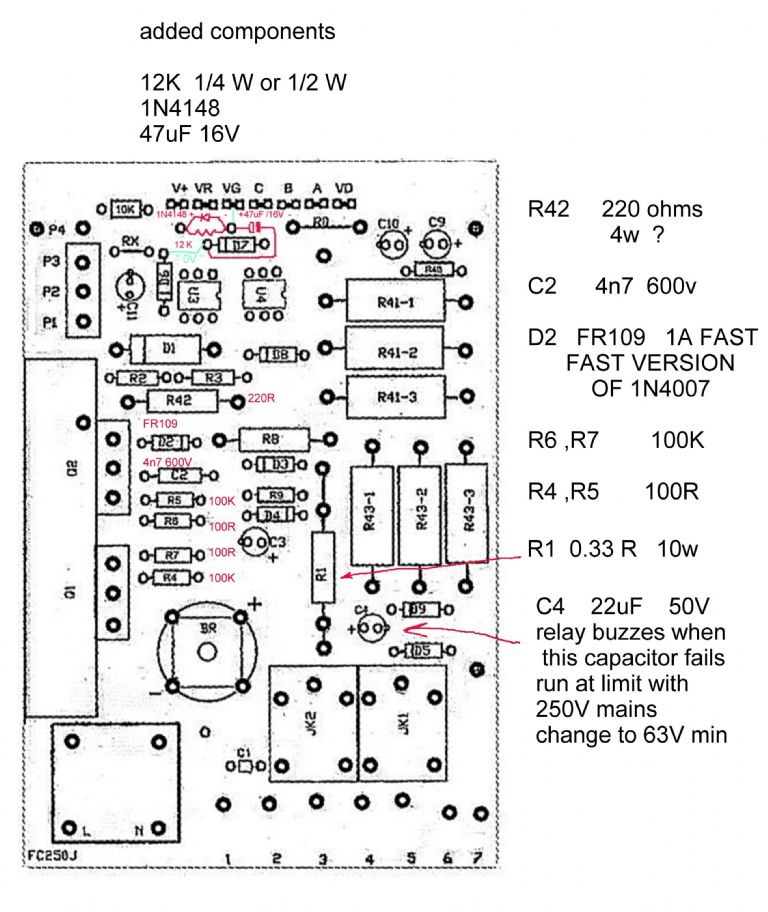
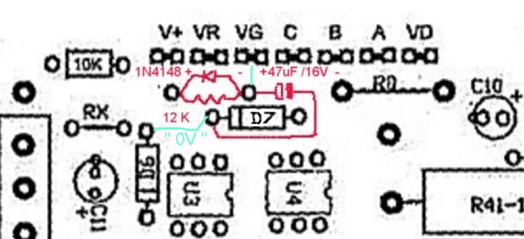
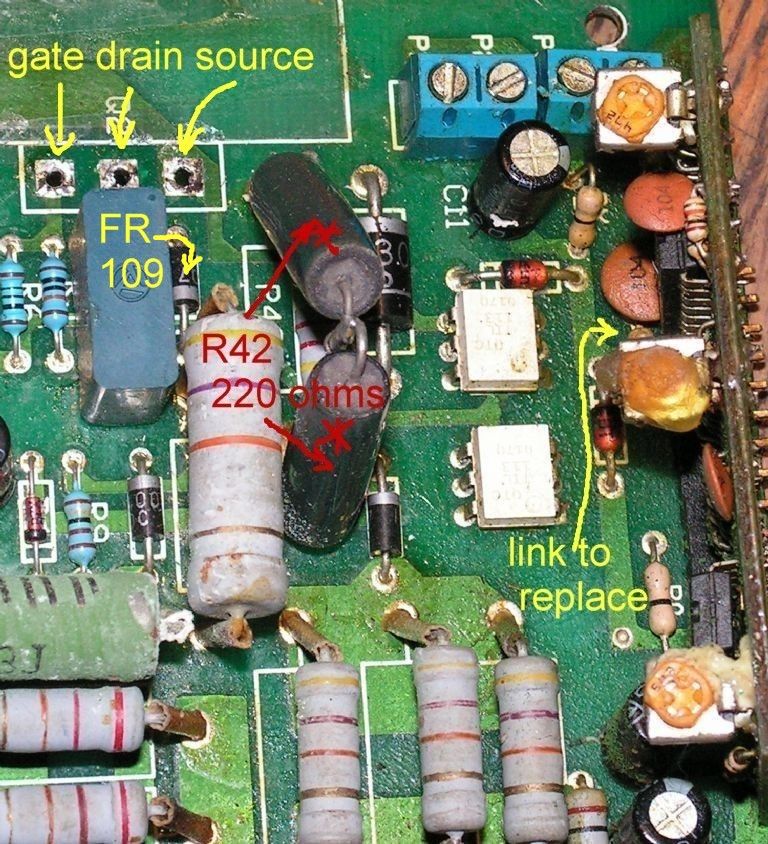
speed control pcb for Clarke CL300 lathe
speed control pcb for Clarke CL300 lathe
- This topic has 225 replies, 48 voices, and was last updated 15 June 2022 at 19:06 by
 jacek nowak.


 . I have older FC250/230V with FETs on the left. My broblem: first it was not completely stop the engine. The engine is still spinning slowly. I set the trimmers to the daughter board and all was ok. But only for a two days. Then the same problem. Setting trimmer has had no effect. There’s so much that it now has no response to rotation of the potentiometer knob. I allready replace the both FET transistors, Til 113 and LM324N. But nothing. It seems to me that a daughter board is not working as it should. Voltage on the optocouplers does not change when I turn potentiometer. Would help me if I knew what the approximate voltage should be on U1c pin 8,9 and U2a pin 2,1 at potentiometr set min. and max position. Or any other ideas how to revive the regulator? Can anybody help me? Than you very much for any reply.
 .
. 
- Please log in to reply to this topic. Registering is free and easy using the links on the menu at the top of this page.
Latest Replies
-
- Topic
- Voices
- Last Post
-
-
Starrett and other tool manufacturer wood boxes
Started by:
Ian Owen NZ
in: Workshop Tools and Tooling
- 1
-
6 July 2025 at 02:06
Ian Owen NZ
-
Bentley BR2 Rotary Aero Engine
Started by:
notlobgp14
in: Miscellaneous models
- 4
-
5 July 2025 at 22:46
notlobgp14
-
New member
Started by:
nige1
in: Introduce Yourself – New members start here!
- 3
-
5 July 2025 at 22:41
notlobgp14
-
M type top slide conversion??
Started by:
jimmyjaffa
in: Beginners questions
- 7
-
5 July 2025 at 22:10
jimmyjaffa
-
Starrett micrometer.
Started by:
Graeme Seed
in: Workshop Tools and Tooling
- 7
-
5 July 2025 at 21:30
peak4
-
Twin Engineering’s heavy mill/drill quill removal
Started by:
Martin of Wick
in: Manual machine tools
- 11
-
5 July 2025 at 21:10
Martin of Wick
-
Dial test indicator vs Dial indicator
Started by:
martian
in: Workshop Tools and Tooling
- 17
-
5 July 2025 at 20:19
martian
-
Speed camera
1
2
3
Started by:
David George 1
in: The Tea Room
- 23
-
5 July 2025 at 19:40
John Haine
-
Sanjay’s Banjo Engine
Started by:
JasonB
in: Stationary engines
- 3
-
5 July 2025 at 19:14
JasonB
-
Any ideas how to repair this?
Started by:
Ian Parkin
in: Related Hobbies including Vehicle Restoration
- 11
-
5 July 2025 at 15:36
Pete Rimmer
-
Chucking Money Away!
Started by:
Chris Crew
in: The Tea Room
- 6
-
5 July 2025 at 12:55
Chris Crew
-
2 Machine lights
Started by:
modeng2000
in: Workshop Tools and Tooling
- 2
-
5 July 2025 at 11:58
Dalboy
-
Boxford lathe & vertical mill VFD conversion help with start stop
Started by:
Andrew Schofield
in: Beginners questions
- 8
-
5 July 2025 at 11:39
Clive Brown 1
-
1965 Colchester Chipmaster
Started by:
andyplant
in: Introduce Yourself – New members start here!
- 6
-
5 July 2025 at 11:09
Rod Renshaw
-
What Did You Do Today 2025
1
2
…
6
7
Started by:
JasonB
in: The Tea Room
- 33
-
5 July 2025 at 09:26
Nick Wheeler
-
Amadeal AMABL210E Review – Any Requests?
1
2
Started by:
JasonB
in: Model Engineer & Workshop
- 16
-
5 July 2025 at 05:49
Diogenes
-
ML10 backgear
Started by:
alexander1
in: Manual machine tools
- 3
-
5 July 2025 at 00:11
Bazyle
-
The Perpetual Demise of the Model engineer
Started by:
Luker
in: Model engineering club news
- 13
-
4 July 2025 at 17:06
JasonB
-
Colchester Chipmaster Clutch question
Started by:
Peter_H
in: Manual machine tools
- 3
-
4 July 2025 at 16:44
notlobgp14
-
Advice moving 3x machines
Started by:
choochoo_baloo
in: Workshop Techniques
- 5
-
4 July 2025 at 15:46
Bazyle
-
Black plastic to replicate Bakelite
Started by:
Craig Brown
in: Materials
- 8
-
4 July 2025 at 15:35
nj111
-
Firth Valve Gear
Started by:
Andy Stopford
in: Traction engines
- 10
-
4 July 2025 at 14:42
duncan webster 1
-
A Persistent Scam
Started by:
Chris Crew
in: The Tea Room
- 5
-
4 July 2025 at 14:23
Speedy Builder5
-
Hemmingway rotary broaching kit
Started by:
YouraT
in: Workshop Tools and Tooling
- 4
-
4 July 2025 at 09:02
jimmy b
-
Collet closer identification.
Started by:
vic newey
in: Workshop Tools and Tooling
- 10
-
3 July 2025 at 22:36
richlb
-
Starrett and other tool manufacturer wood boxes
Latest Issue

Newsletter Sign-up
Latest Replies

