speed control pcb for Clarke CL300 lathe

Advert

speed control pcb for Clarke CL300 lathe

Home Forums Manual machine tools speed control pcb for Clarke CL300 lathe

Viewing 25 posts - 51 through 75 (of 226 total)
  • Author
    Posts
  • #59025
    Ian S C
    Participant
      @iansc
      Think I’ll stick to my belt head, back geared, 20+ year old Taiwanese lathe, although some times I would like it to be gear headed, but as it was 20 years ago, I’ll keep away from electronics, just KISS. Ian S C
      Advert
      #59129
      William Smiles
      Participant
        @williamsmiles10916

        Hi Guys,>>

         >>

        I have just purchased a second hand CL300M Metal Lathe but unfortunately it is missing the control box and all its components. I just wondered if anybody knew where I might get the whole unit without having to buy all the individual components from Clarke’s spares. I have read all your post with interest and realize that the most vulnerable component seems to be the electronic controller. I am a beginner to all this, but have some grounding in electronics. Would it be possible to buy the reversing switch, potentiometer (speed controller), fuse holder etc from reputable electronic firms such as Maplins or Rapid. Although the switch and pot etc have values they have no ratings e.g. wattage. Could you give me an idea of what I would require as I do not want to fit something to a new board which is going to create problems? I obviously have none of the orginal components to make comparisons.

        I would also welcome any advice on fitting and wiring up the components as I note a number of connecting posts on the side of the lathe. Thanks in anticipation of a reply.

         
        [img]http://img140.imageshack.us/img140/6551/lathe.jpg[/img]

        Edited By William Smiles on 22/11/2010 16:25:03

        Edited By William Smiles on 22/11/2010 16:28:30

        #59130
        William Smiles
        Participant
          @williamsmiles10916

          Edited By William Smiles on 22/11/2010 16:26:18

          #59135
          William Smiles
          Participant
            @williamsmiles10916

            Hi Guys,

            Sorry to post again but have just found how to post a photo. I now include a photograph so you can see my starting point.

            I have just purchased a second hand CL300M Metal Lathe but unfortunately it is missing the control box and all its components. I just wondered if anybody knew where I might get the whole unit without having to buy all the individual components from Clarke's spares. I have read all your post with interest and realize that the most vulnerable component seems to be the electronic controller. I am a beginner to all this, but have some grounding in electronics. Would it be possible to buy the reversing switch, potentiometer (speed controller), fuse holder etc from reputable electronic firms such as Maplins or Rapid. Although the switch and pot etc have values they have no ratings e.g. wattage. Could you give me an idea of what I would require as I do not want to fit something to a new board which is going to create problems? I obviously have none of the orginal components to make comparisons.

            I would also welcome any advice on fitting and wiring up the components as I note a number of connecting posts on the side of the lathe. Thanks in anticipation of a reply.

            Edited By William Smiles on 22/11/2010 17:13:51

            Edited By Katy Purvis on 01/06/2015 12:00:58

            #59138
            john swift 1
            Participant
              @johnswift1
              Hi William ,
               
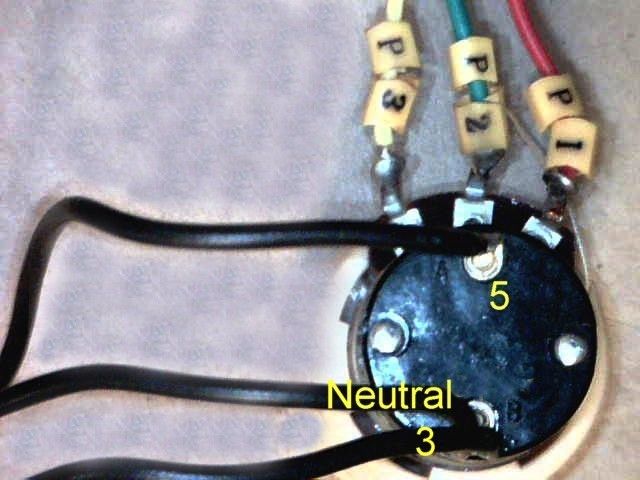
              the speed control is a special  5k linear potentiometer with a singl pole switch
              that is closed when the control is fully anticlockwise (part of the interlock circuit)
              this makes you start at minimum speed
               
              on my version of the lathe
              the forward/off/reverse switch is a 10A 250v    4 pole 3 way switch   , this is to stop you changing direction with the motor running
               
              2 of the poles control the motor direction
              the 3rd selects  the maximum speed  ,  reverse is about 50% of that  in forward
              and the remaining pole is part of the power control interlock –
              so the machine switches off as you change direction
               
               Machine Mart , Chester Machine Tools , Arc Euro Trade etc can supply the parts for the lathe
               but I don’t know if they sell the parts you require as a kit of parts
              but little machine shop do (when its  in stock)
              part number 3200  (the 230v version !)
               
              first you need to decide if your using the original FC250J/230v or later XMT2325
              control board and test the motor just in case thats why the control is missing
               
              do you have the manual ?
              if not you can down load the latest version from MachineMart
              or another version from little machine shop
               
              I’ll have a look for a picture of inside the control box
               
                  John
               
              #59142
              William Smiles
              Participant
                @williamsmiles10916
                Thanks you very much for the information John,
                 
                It is very helpful. Looking at  your lead to Little Machine Shop it is going to work out much cheaper going in this direction. I do not know how long they have been out of stock or how long they are likely to be out of stock, but the whole unit works out at less than £100. Of course there will be postage on top of that, but looking at the cost of the bits it looking like it would be much more expensive to build it myself and then there is always the chance that you make a mistake and blow other components.
                 
                By the way I do not know whether this makes the motor ok or not but it will turn if 12V DC (Car Battery) is applied to it, or is this just been naive?
                 
                I appreciate any photos of the inside as I still have to connect it up and have no prior information to work on.
                 
                Thanks for all your help so far.
                 
                Best wishes,
                 
                Bill.

                Edited By William Smiles on 22/11/2010 18:59:37

                #59150
                William Smiles
                Participant
                  @williamsmiles10916
                  Hi John,
                   
                  Have order the part from Little Machine as they actually had the part in stock, even though it was showing as out of stock. The cost in totally was approximately £110.00 that included postage and taxes. I am certain I would not have been able to buy the separate parts for less than this. So thank you very much for the information.

                  By the way I do not know whether this makes the motor ok or not but it will turn if 12V DC (Car Battery) is applied to it!!! or is this just been naive?
                   
                  I appreciate any photos of the inside as I still have to connect the unit up and have no prior information to work on.
                   
                  Thank you very much for all your help so far.
                   
                  Best wishes,
                   
                  Bill.

                  #59180
                  john swift 1
                  Participant
                    @johnswift1
                    Hi Bill ,
                     
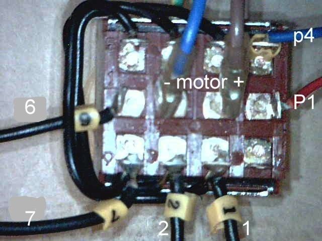
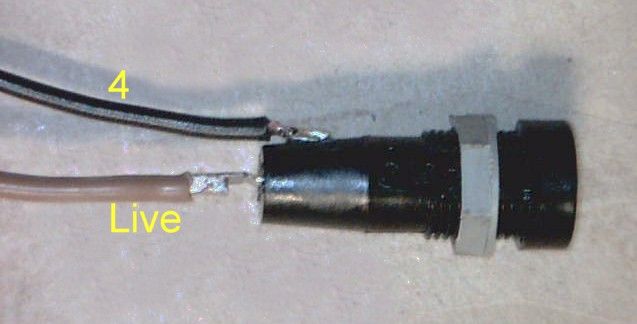
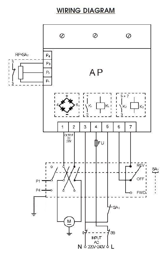
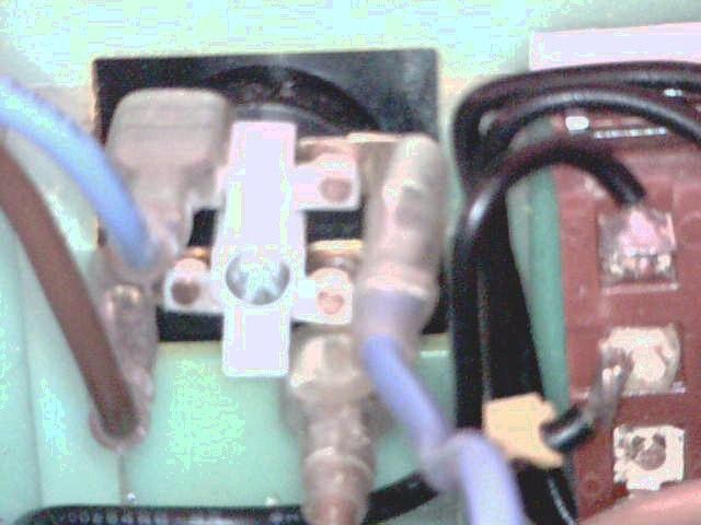
                    just some pictures of the control box wiring
                     
                      (the first picture shows a later pcb than the board I have )
                     
                     
                    the motor running on 12v is a good sign
                    the brushes are about 14mm long when new
                    I’d expect to replace them at 7 or 8 mm
                     
                    if you can look through the rear cover and check the commutator is still a copper colour
                    and not burnt black
                     
                    ideally you need an insulation tester to check the insuation between the dc in wires and the motor body
                     but its worth checking it reads open circuit with a multimeter
                     
                        John
                     
                     
                    #59181
                    William Smiles
                    Participant
                      @williamsmiles10916
                      Hi John,
                       
                      Thank you so much for the trouble you have gone to, to send me photos and all the information, I am very grateful. I now wait for the unit to arrive from the states. I have only just realize that the states electrical supply is 120V, will this mean the the PCB controller will need some component changes to work in this country or even worse that the unit will not work here at all? Or do they use some form of step up transformer in the states to make the lathe work?
                       
                      I have just one other question that I cannot see from the photographs. Does the power chord hook onto the emergency stop button. From the circuit diagram it looks like it does, but the guy from the states said it hooks onto the main PCB board. If this is true I cannot see how. Look forward to your reply.
                       
                      Kind regards,
                       
                      Bill Smiles.

                      Edited By William Smiles on 23/11/2010 05:34:25

                      #59183
                      Les Jones 1
                      Participant
                        @lesjones1
                        Hi Bill,
                                     I have noticed this morning (23/11/10) that someone is selling a control box for a Chester Conquest lathe on Ebay. I think this is the same as the CL300. It is faulty but could probably be repaired   The item number is 290503483892  It is a pity that you have already ordered one.
                        Les.
                        #59184
                        john swift 1
                        Participant
                          @johnswift1
                          Hi Bill ,
                           
                          just checking  did you order part number 3200    the 230v kit
                           
                          or part number 3042  the 110v version ?
                           
                          if you can stop the order and reorder the correct one
                           
                          if you look at the boards the 9 large resistors along the edge of the board and 2 x 5w
                          resistors in the centre of the board  
                          determine  the voltage the board works on ( just need to confirm 24v relays are used on both boards) so it should be easy to convert the board if you had to
                           
                          the LMS control board is pn 1336 for 110v and 2526 for 230v
                          (have a look at the picture in my post to Richard on 10/08/2010)
                           
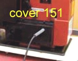
                          do you have the mains cable (124), motor cover (151) cable gland(152), protector(174)
                          (marchine mart part numbers HT300M151 HT300M152 , HT300M124 , HT300M174)
                           
                           
                          yes the mains cable connects directly to the red stop switch
                          a wire on the fuseholder and on interlock switch on the potentiometer
                          then plugs onto the switched mains side


                           John

                          Edited By john swift 1 on 23/11/2010 10:40:49

                          Edited By john swift 1 on 23/11/2010 11:05:43

                          #59192
                          john swift 1
                          Participant
                            @johnswift1
                            Hi Bill ,
                             
                            just an update
                             
                            having had a close look a at my circuit and some info of the web
                            it looks like 2 or 3 surface mount resistor may need changing
                             
                            this is were I need to have the circuit or a high resolution photo of a 110v board
                            to read the values of the surface mount resistors
                             
                            still a viable plan B , if exchanging a 110v board is expensive
                             
                                    John


                            Edited By john swift 1 on 23/11/2010 15:09:01

                            Edited By john swift 1 on 23/11/2010 15:10:27

                            #59198
                            Robert Smith 10
                            Participant
                              @robertsmith10
                              Thanks for the earlier reply …I’ve now ordered an XMT board from ArcEurotradde (on the basis I have a faulty one from when I originally purchased the lathe – so might be some spare part on there!)
                              #59204
                              William Smiles
                              Participant
                                @williamsmiles10916
                                Hi John,
                                 
                                Thanks for the earlier reply and photos. I have checked with supplier and I have ordered the 240V board  (sigh of relief). I do not have any of the component you suggested only what you can see on the earlier picture. Will I need to order these?
                                 
                                I have not got the following components;      
                                 
                                Mains Cable  CL300M124, Cable Gland CL300M152, Protector CL300M174, Motor Cover CL300M151
                                 
                                Where would I order them? I only ask this because Clarke’s only carry the most common spares. Will I need to go back to the American Supplier? I assume I can easily make a mains cable and get hold of a cable gland from any electrical store!
                                 
                                The belt on the motor also feels very slack, is this normal or should I order one of these at the same time. Have not had a chance yet to check the brushes, do you know of a good place to order these?
                                 
                                Thanks for your continuing support.
                                 
                                Bill

                                Edited By William Smiles on 23/11/2010 18:00:57

                                #59205
                                William Smiles
                                Participant
                                  @williamsmiles10916
                                  Hi Les,
                                   
                                  Thanks for the information about the second hand controller. I have already order one but have put a bid in anyway, if I can repair it it would be a useful spare.
                                   
                                  Kind regards,
                                   
                                  Bill.
                                  #59211
                                  john swift 1
                                  Participant
                                    @johnswift1
                                    Hi Bill ,
                                     
                                    had a quick look at the Arc Euro Trade’s C3 spares 
                                     
                                     and found the brushes (£3.50) and belt (£5)  ,  the cover is out of stock
                                     
                                    little machine shop has more


                                    check the LMS cover  is 170mm x 95mm x 50mm
                                     
                                     the only cable gland I’ve found is Maplin’s JZ43W
                                    you just need some thing to protect the cable from
                                     the clamp and the edge of the exit hole in the cover
                                     
                                    the belt may just need adjusting
                                    its not easy – you will end up doing it a few times at first
                                     
                                    two studs pass through the slots in the bed to hold the motor in place
                                    and the two grub screws push on the motor body to give a small
                                    vertical adjustment
                                     
                                    eg by screwing the top screw in and the bottom screw out
                                    the motor will be deflected down to tighten the belt
                                     
                                                            John
                                     

                                    Edited By john swift 1 on 23/11/2010 20:04:36

                                    #59219
                                    William Smiles
                                    Participant
                                      @williamsmiles10916
                                      Hi John,
                                       
                                      Thanks again for all your hard work and effort, would never have been able to do it without you. I have now ordered everything except the cable gland and the mains cable but I am sure I can make do with what I have in my workshop for both these items. I will now have to wait until they are delivered from the USA before I can proceed any further but I am pretty sure I will need to call upon your skills again. I have put a bid in on E-Bay for a second hand complete controller box that states that the PCB controller has something wrong with it. If I win the item I will try and repair it from the information you give in your earlier posts, but might need to contact you again if things do not work out. Just one further question relating to the photograph showing the protector component. This photograph shows approx 8 wires, as far as I can see with my lathe  there will be the motor wires (3 inclusive of earth), the mains cable  (3 inclusive of earth), so where are the other two wires coming from????
                                       
                                      Cannot thank you enough.
                                       
                                      Kind regards,
                                       
                                      Bill.
                                      #59220
                                      john swift 1
                                      Participant
                                        @johnswift1
                                        Hi Bill ,
                                         
                                        the extra 2 blue wires that go into the headstock go to a microswitch
                                        on the chuck guard
                                         
                                        this switch is not fitted on our version of the lathe
                                        the photo was the best I could find to show the protector in position
                                         
                                        the only manual for the lathe to download from machine mart  is for the latest version
                                        ( I have a pdf copy of your manual )
                                         
                                         
                                        the main change is the use of the xmt2325 control pcb
                                         
                                                          John

                                        Edited By john swift 1 on 23/11/2010 22:25:58

                                        #59236
                                        William Smiles
                                        Participant
                                          @williamsmiles10916
                                          Hi John,
                                           
                                          Thanks for the info, I am pleased that there is nothing else missing. I now await the delivery of the parts and will contact you then for further assistance.
                                           
                                          Best wishes,
                                           
                                          Bill
                                          #59676
                                          William Smiles
                                          Participant
                                            @williamsmiles10916
                                            Hi John,
                                             
                                            I have now received the controller and box etc. I was a little surprised as I expected it to come as an assembled unit, but it arrived as a kit which has to be built up. I have been working on the circuit drawings and using your photo’s as a guide. Just one thing, it looks like you have an earth wire attached to the Forward Reverse switch. Is this correct? I assume it is connected to the main body via the nut that secures it to the control box. Again is this correct? Are there any other earthing wires which I need to attach? I have the one for the motor and the mains cable! Thanks for your ongoing support.
                                             
                                            Best wishes,
                                             
                                            Bill.
                                            #59677
                                            john swift 1
                                            Participant
                                              @johnswift1
                                              Hi Bill ,
                                               
                                              thats good , only taken a week at this time of the year
                                               
                                              because the box is plastic
                                              a short wire connects the switch body to one of four  earth points on the head stock
                                              in addition to  the motor , and mains cable earth
                                               
                                              on your picture you will see four screws with  star washers to secure the earth wiring
                                              ( only three used )
                                               
                                              I expect the one earth wire  in your  picture is from the motor body
                                              the motor cable and mains cable passes through the same hole the the bed
                                              the plastic protector stops the wires being damaged by the leadscew
                                               
                                               four counter sink screws ( m5 x 10mm ) are just used  for fastening the control box to the headstock and bed – don’t over tighten , you could split the plastic !
                                               
                                              did you download the manual ?
                                               
                                               John
                                               
                                              #59755
                                              William Smiles
                                              Participant
                                                @williamsmiles10916
                                                Hi John,
                                                 
                                                Thanks again for the information. Are the screws on the motor box the same (Counter sink screws M5 x 10mm) or are they different? The screws for the motor control box are actually there but the motor box screws are not. Do you also know what screws are used to attach the PCB Board to the plactic body (size and type) and the screw size of the ones that attach the emergency buttons, both to the box and hold the unit together? Would have thought they might have included these with the kit, along with a potentiometer knob, but these were not included or at least not in my package. Still waiting for the second package, which includes the wire protector and motor box, but given the weather conditions today (over two foot of snow on the ground and it still continues) it might yet be a few days before they can deliver it. Yes have downloaded the manual.
                                                 
                                                You are correct the earth wire was from the motor, but was not connected at either side. I have made up a mains lead, which is ready to connect but I will need to wait until all the parts have arrived before I can do this properly. Have you any advice on the wire size and type used for the connections to switch(FOR), emergency switch, potentiometer and PCB Controller? Any information will be helpful. Thanks again for the great info already supplied.
                                                 
                                                Best wishes,
                                                 
                                                Bill.

                                                Edited By William Smiles on 01/12/2010 16:17:03

                                                Edited By William Smiles on 01/12/2010 16:20:22

                                                #59853
                                                john swift 1
                                                Participant
                                                  @johnswift1
                                                  Hi Bill ,
                                                   
                                                   
                                                   the motor cover is held by the same type of screws as the rear splash guard – M5 x 8 pan head
                                                   
                                                   the screws attaching  the pcb as far as i can tell are
                                                    no 4  self tapping screws   3mm dia x 6.5mm
                                                   
                                                  the  4  for the pcb cover are no5 self tapping screws     3.7mm dia x 8mm
                                                   
                                                  i’ve not found any supplier for small quantities (10) 
                                                  try Machinemart first
                                                   
                                                  ( chipboard screws are the nearest but with counter sink heads
                                                  add a washer to  protect the pcb  
                                                   
                                                  the mains cable is 3 core 6A  ~ 6.5 mm dia
                                                  most of the wiring can be
                                                  Maplin   black  6A  equipment wire   KR31J       24/0.2
                                                   
                                                  use eyelet   JH62S for connections  to earth on the headstock
                                                       spade     JH64U for pcb terminals 1 to 7
                                                  lucar f/m      HF10L  for connection to the emergency stop
                                                  lucar boot    FE65V  for 1/4″ connector HF10L
                                                  fuse holder boot FT35Q extra insulation not on original 
                                                  just ensure the LIVE connection is to REAR terminal and not the side terminal
                                                  ( if you remove a good fuse with the power on , you could get a shock if 
                                                  you have  it the wrong way round ) 
                                                   
                                                   wires P1 to P4   can be connected with wire like    3A  equipment    FA36P    16/0.2 
                                                   
                                                  the motor wires have as smaller f/m lucar terminal to fit the terminals
                                                  on the forward /reverse switch  –  4.8mm  N35CY
                                                  add cable markers to make it easy to identifiy the cables
                                                   
                                                  if you don’t have one
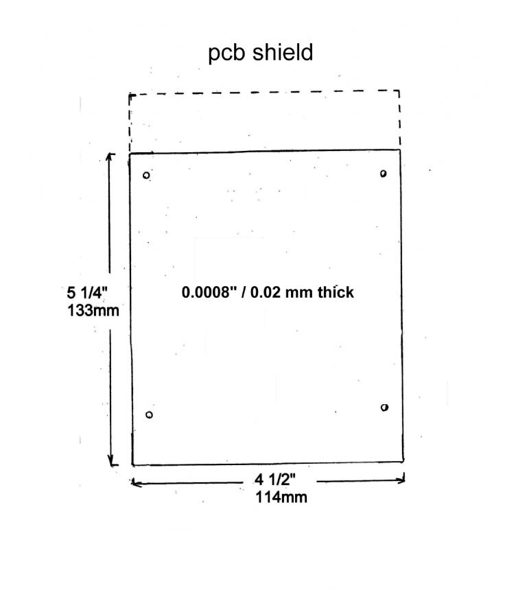
                                                  the plastic cover for the pcb is    133mm x 114 mm  , 0.2 mm thick
                                                   
                                                  i made an extra  one , about 25mm longer , with the extra bit bent at right angle to
                                                  make contact with the headstock
                                                   

                                                  hope this helps

                                                   
                                                      John

                                                  Edited By john swift 1 on 03/12/2010 00:20:31

                                                  Edited By john swift 1 on 03/12/2010 00:21:52

                                                  #59881
                                                  William Smiles
                                                  Participant
                                                    @williamsmiles10916
                                                    Hi John,
                                                     
                                                    Thanks again for the incredible detailed and useful information you have supplied. Once I have the components I will be able to assemble. Just one thing I was unsure about. You meantion a PCB shield, which certainly did not come with the kit. If the shield is over the PCB board would it not require pillars to make it stand off from the PCB Components. Having just looked at the box I now assume that the four plastic pillar posts within the controller box are what the PCB Shield attaches to and I can now see why the 25mm would make it touch the headstock. It still surprises me that they sell a kit which does not contain all the components required to build the complete box. I assume the shield would be okay in perspex. I have not got a heat srip to bend the plastic but I am sure I can rig something up. Again thanks for your invaluable advice and support.
                                                     
                                                    Regards,
                                                     
                                                    Bill.
                                                    #60253
                                                    Daryl Heasman
                                                    Participant
                                                      @darylheasman56468
                                                      Hi guys
                                                       
                                                      Is there an easy way to change or put on a new drive belt on a Clarke cl300m lathe without taking it to bits ,or am i missing something
                                                       
                                                      regards
                                                       
                                                      Daryl
                                                    Viewing 25 posts - 51 through 75 (of 226 total)
                                                    • Please log in to reply to this topic. Registering is free and easy using the links on the menu at the top of this page.

                                                    Advert

                                                    Latest Replies

                                                    Home Forums Manual machine tools Topics

                                                    Viewing 25 topics - 1 through 25 (of 25 total)
                                                    Viewing 25 topics - 1 through 25 (of 25 total)

                                                    View full reply list.

                                                    Advert

                                                    Newsletter Sign-up