speed control pcb for Clarke CL300 lathe

Advert

speed control pcb for Clarke CL300 lathe

Home Forums Manual machine tools speed control pcb for Clarke CL300 lathe

Viewing 25 posts - 26 through 50 (of 226 total)
  • Author
    Posts
  • #54273
    Richard Edmonds
    Participant
      @richardedmonds33836
      Well Gents it would seem that I am in your debt. Contact with you lads has saved me probably £119.82 in the price of an 18 pence capacitor from Maplin. I realise exactly now what has been said about the various other connections within the control unit. and now realise why a £350.00 lathe is 350 quid. Had a hell of a job making all the cheap connectors work so will change them all later for some proper ones. So really chaps thanks again I am so very grateful for your excellent help
       
      Regards
      Richard
      Advert
      #54277
      john swift 1
      Participant
        @johnswift1
        Hi Richard ,
                            Its good to see your lathe is working
        It’s a good feeling isn’t it , when you fix some thing
        You will find  capacitors are the cause of many of the faults in equipment that runs hot
        about 90% of the lcd monitors I have repaired needed only 4 new capacitors
        a life of upto 2000 hours at 105 C is not very long some times !!
         
                     John
        #54280
        Richard Edmonds
        Participant
          @richardedmonds33836
          Hi John
          Yes it does feel good to repair something for a change. However thanks to you because without your input I would not have a clue as to what was wrong. Maybe I should learn though as that info would probably save me hundreds when the boiler packs up or any other machine does as well
          Thanks again John
          Regards
          Richard
          #55811
          Daryl Heasman
          Participant
            @darylheasman56468
            Hi Guys im very new to this site . I have a problem with my CL300M lathe and am wondering if anyone can help . I burnt the motor out and there was a bang from somewhere in the control box when it went , I have replaced the motor with a new one from Clarke only to find i have no speed control at all  its full speed or nothing ,Clarke advise the PCB has also gone and on reading all the posts relevent i see some of you guys are very clued up on this subject . Can anyone advise what to look for and how to test this board as Clarke want another £85.00 for a new board which seems outrageous as i have already spent £127 on the motor
             
            thanks in advance
             
            Daryl 
            #55814
            Michael Cox 1
            Participant
              @michaelcox1
              Hi Daryl,
              I have a Clarke CL300M lathe. The spead control board on mine is type FC250J. This is printed on the board. ArcEurotrade are selling this board at £60 – see http://www.arceurotrade.co.uk
              Unfortunately they are currently out of stock but it maybe worth enquiring when more is due. They are a very good and reliable outfit in my experience.
              Mike
              #55823
              Pat Bravery
              Participant
                @patbravery
                If you are OK with a small soldering iron you can change the mosfets IRFP450 two off and see if that fixes the problem, it worked for me, they are very cheap through ebay, I paid about £6 for the pair. My 300cl had the same symptoms and it has been fine since. Let us know how you get on, forgot to say that mine is a FC250J board. regards Pat

                Edited By Patrick Bravery on 17/09/2010 22:42:40

                Edited By Patrick Bravery on 17/09/2010 22:43:29

                #55825
                john swift 1
                Participant
                  @johnswift1
                  Hi Daryl ,
                   
                  if the control pcb is a FC250 J type old or new version
                  ( have seen one version of the sieg C3 lathe using a xtm…type of controller
                  the control panel has a amber overload light ) 
                   
                  first check the resistance of the two fet’s on the heat sink
                   
                  the resistance across the out side leads should be 50 000 ohms ( the two 100k resistors connected to the gate and source )
                  all other combinations over 1 000 000 ohms
                   
                  if one is short circuit replace both with  IRFP450 (eg RS components pn 541-0058 @£3-34)
                   
                  if the fets are ok  , check the speed control
                  the voltage between terminals p3 and p2 varies from 0 volts at minimum speed to
                  +12v at maximum
                   
                   even with a faulty speed control potentiometer that gives you maximum speed all the time
                  the output should drop when you switch from forward to reverse — do this test with a 60 or 100w gls bulb instead of your new motor !
                   
                   
                            John Swift
                   

                  Edited By john swift 1 on 17/09/2010 23:44:36

                  #55826
                  Daryl Heasman
                  Participant
                    @darylheasman56468
                    Thanks guys do you have a picture of the relevent parts to try changing,soldering is no problem if i can identify the parts to change 
                     
                    regards
                     
                    Daryl
                    #55836
                    Daryl Heasman
                    Participant
                      @darylheasman56468
                      Hi Guys is it worth trying the speed control switch first as mine has no control at all and even works in the off position . The only on off switch now is the forward and reverse switch in the middle position . I have several speed switches of varying types  from mig welders so can i use one of these to test it ,  As your probably aware now i really dont have a clue what all the bits are called which is the reason for asking so please bear with me guys
                       
                      regards
                       
                      Daryl
                      #55848
                      john swift 1
                      Participant
                        @johnswift1
                        Hi Daryl ,
                                       hope the photo’s help
                         
                         
                        the resistance between the gate and source terminals is 50K
                        all other combinations over 1m0  ( virtually open circuit )
                         
                        you can test the board to some extent with out a speed control potentiometer
                         
                        you can fit wire links for min speed , half speed ( rev full speed ) and  maximum speed
                         
                        p2 + p3 ,  or    p1 + p2       or      p1 + p2 +p4
                         
                         
                         remember all the pcb is live ! and use a tungsten lamp as a load , not the motor
                         
                               john
                         
                         
                        ps        on later the version of the pcb all the terminals are in line on one end of the pcb
                         
                                    and the fet are IRFP450’s
                         

                        Edited By john swift 1 on 18/09/2010 14:55:25

                        Edited By john swift 1 on 18/09/2010 15:18:33

                        Edited By john swift 1 on 18/09/2010 15:23:13

                        #55855
                        Daryl Heasman
                        Participant
                          @darylheasman56468
                          Hi John the last picture of your post ,is this the old pcb or the later one as this board is the same as mine . The reason i ask is that Clarke sent me pictures showing this as the old type board,so now confused
                           
                          regards
                           
                          Daryl 
                          #55858
                          john swift 1
                          Participant
                            @johnswift1
                            Hi Daryl ,
                                            the last picture is the later version with the surface mount components
                            the other pictures are of my old control board
                             
                             
                            the FET’s you need to check are on the heatsink , on the left
                             
                              if you disconnect the 5 wires from terminals P 1 to P4    ( the blue connector)
                            and link P2 and P3 the motor should run at the minimum speed unless the FET’s are short circuit 
                             
                             
                            connect a test lamp to terminals DC1 and DC2 instead of the motor
                            until you have fixed the fault
                            applying full power to the motor with out starting from minimum could damage it
                             
                             
                                 John
                            #55867
                            john swift 1
                            Participant
                              @johnswift1
                              Hi Daryl ,
                                             I’ve just had a look at the CL300M lathe on the machine mart site
                               
                              the new manual shows the speed control pcb is XMT-2325 !
                              (arceurotrade has a picture of it in the C3 spares)
                              the XMT…. series of controller have been used on the milling machines for some time
                               
                              that explains the confusion  
                               
                              this newer type of controller uses two thyristors and three diodes on five small heatsinks
                               instead of two fet’s on a large heatsink and a bridge rectifier used on the FC250J control
                               

                              Edited By john swift 1 on 18/09/2010 20:48:10

                              #55885
                              Daryl Heasman
                              Participant
                                @darylheasman56468

                                   Thanks John and all you other guys ,been a great help

                                #58870
                                robert glover 1
                                Participant
                                  @robertglover1
                                  HI’ all I am new to this site and wonder’ if someone can help me ‘ I have had a short caused by rain water ‘ and have blown  my SMD-FC250J circuit board it’s that bad’ part of the tracking has gone’ and I am not sure what the missing part should look like’ it’s missing the part on the rear face under the DC1 DC2 connections. Anyone have a photo of the back of the board so i can repair it? I know it may not be worth the effort but I would at least like to try’ as the conponets that you would think should have gone seem to be ok.  THANKS A LOT Bob.
                                  #58881
                                  john swift 1
                                  Participant
                                    @johnswift1
                                    Hi Bob ,
                                     
                                    do you have a picture of the damage ?
                                                       

                                    hope this helps
                                     
                                     
                                    check the bridge rectifier and fets are ok
                                    and the pcb is not burnt between terminals dc2 and ac3
                                     
                                    for initial tests wire a 60W or 100W gls bulb in series with the fuse
                                    and a 15W pigmy bulb in place of the motor
                                     
                                    ( the 60 / 100W bulb will limit any fault current if any short circuit still exists
                                    the 15w bulb is just a load / indicator )
                                     
                                     
                                          John
                                    #58918
                                    robert glover 1
                                    Participant
                                      @robertglover1
                                      HI john thanks for reply’and photo’ but it does not look like mine? are there 2 types? see photos.   The board went with hell of a POP   
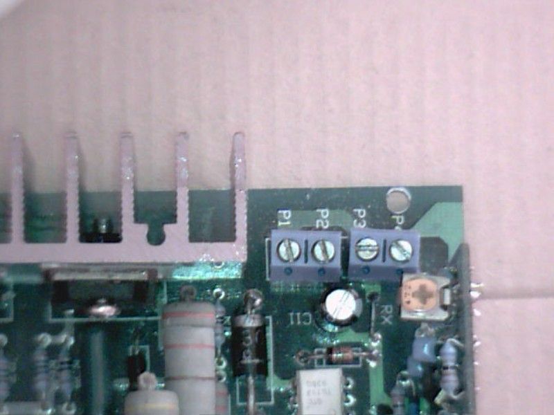
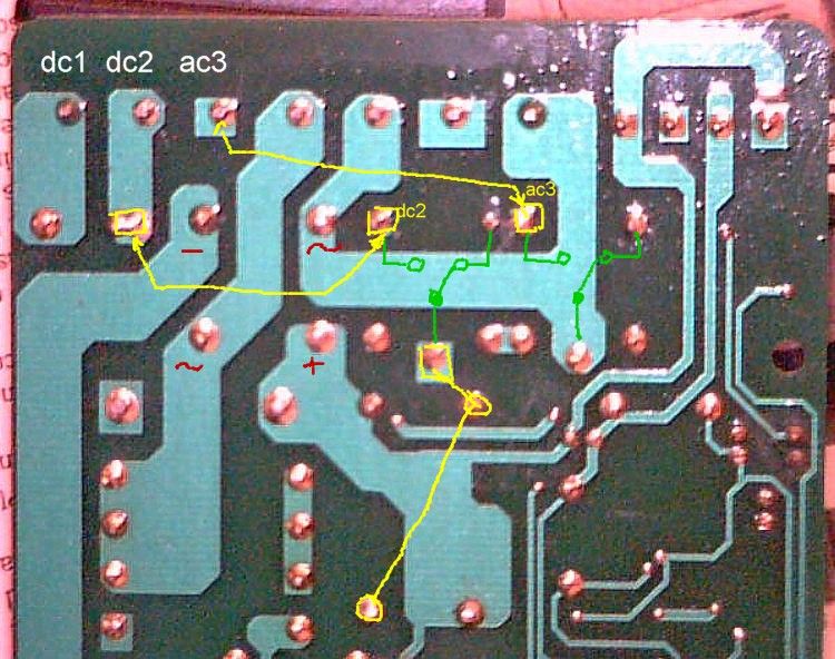
but did not blow the bridge rectifier or the motor’ I have had the motor tested by my nephew who works for a rewind company and it’s OK’ and I have sort off figured out the component side of the CB there is a bit of L shaped tracking missing between DC2 and the rectifier leg’ also there is a capacitor next door to the rectifier; do you know it’s value?. I have repaired the hole since the photos  John don’t know whats gone wrong with photos they seem to have got lost must have done something wrong? they only place they show up is in albums? 

                                      ‘ so any MODS and NEW tracking will need to be done on the back of the CB’ if I can find out what it looks like. PS.  I took the rectifier out for a better photo.  Can anyone help with a photo. THANKS AGAIN JOHN regards Bob.

                                      Edited By robert glover 1 on 17/11/2010 20:06:52

                                      Edited By robert glover 1 on 17/11/2010 20:13:36

                                      Edited By robert glover 1 on 17/11/2010 20:31:03

                                      #58922
                                      john swift 1
                                      Participant
                                        @johnswift1
                                        Hi Bob ,
                                        your board must be the first version of the SMT boards
                                        the circuit should the same as the old board I traced at the begining of the year
                                         
                                        the missing capacitor is 47nF 275v and connects across terminals DC1 and DC2
                                        the 0R33 10W resistor on the circuit for  my old board
                                         is 2x 0R66 5W in parallel on the SMT boards ( electrically the same)
                                         
                                        the pcb picture I had is for a later version with the smaller 4 pin opto isolaters
                                        replacing the 6pin (white) ones on your board
                                        plus a simple circuit mod  to limit the rate of speed increase if you turn the speed control  rapidly to maximum
                                         
                                        so I’ve made some notes on your pictures
                                        I think I’ve worked out the missing print ?


                                         good luck
                                           John
                                        #58939
                                        robert glover 1
                                        Participant
                                          @robertglover1

                                            HI’ john thanks a lot for taking the time to do the mods on the photos’  BRILLIANT work’   up to now I have got as far as repairing the hole and replacing the missing  L  shaped tracking on the component side of board’  it looks quite good.   I used a thin piece of copper sheet’   I would have posted a photo’   to let you see how I did it’  as the idea may come in handy sometime’   but being new to this site’  I dont want to make a hash of it’  as I seem to have done last time.   
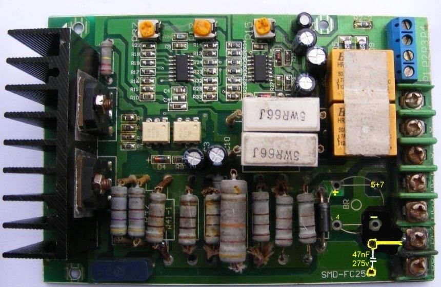
What I could do with is some kind soul to do me a walk through on how to post PHOTOS’ as I am fairly new to computers.    MANY THANKS AGAIN FOR THE TIME YOU MUST HAVE TAKEN’  REGARDS   Bob.     

                                          #58949
                                          Daryl Heasman
                                          Participant
                                            @darylheasman56468
                                            Hi John got my pcb all done and it worked a treat surprisingly for me ,then things went wrong . The new motor i purchased from Clarke threw a wobbly and started to arc which took out the control board again . Next morning i was straight on to Clarkes who the following day (thursday) picked  up  the motor and complete control box  ,the motor was covered by warranty the  box was not but i sent a list of events as they happened and the following monday they arrived back with another new motor and a new pcb fitted to control box all foc ,so there is someone there with a heart and now everything is perfect with the lathe
                                             
                                            regards
                                             
                                            Daryl  
                                            #58971
                                            john swift 1
                                            Participant
                                              @johnswift1
                                              Hi Daryl,
                                               
                                              glad to see you got there in the end 
                                               
                                              success repairing the old board ,always makes you feel good
                                              and after the  setback ,
                                               a 2nd new motor and control board in the end
                                               
                                              what a result one happy customer
                                               
                                               
                                              Regards
                                               
                                                John
                                              #58977
                                              Robert Smith 10
                                              Participant
                                                @robertsmith10
                                                Hi guys….found this thread via Google,
                                                 
                                                I bought a sieg c2-300 off Ebay a while back – the motor board was blown so I slapped a Danfoss S-1000 scr board in – it worked fine.
                                                 
                                                Unfortunately it eventually went bang ….I had a go at fixing it, but without the schematic it’s a big time sump….I’m throwing in the towel & now want to buy a new board…..ArcEurotrade have two boards for the C2-300 lsted….
                                                 
                                                 
                                                an FC250J & an XMT2325
                                                 
                                                iIs there pros & cons here (performance, reliabilty, fixabilty wise)….because I don’t know which one to get!
                                                 
                                                Many thanks,
                                                Rob
                                                #58980
                                                john swift 1
                                                Participant
                                                  @johnswift1
                                                  Hi Rob ,
                                                  I’ve only worked on the FC250J controller
                                                  but I understand the the XMT…  type of controller cuts out if you overload the motor
                                                  and will provide greater motor protection
                                                   
                                                  most of the component  damage due to  a faulty or stalled motor
                                                   I would expect to be :-
                                                   1)  short circuit fets and/or bridge rectifier on the FC250j or
                                                   2)  short circuit thyristors and/or high current diodes on the XMT2325
                                                  all easy to replace and not too expensive
                                                   
                                                  after a few years the FC250J board do have a problem with some of the electrolytic capacitors but they are easy to replace , unlike the surface mount components
                                                   used  on both boards
                                                   
                                                  if you want to be able to repair the board
                                                   the choice may depend on you having the circuit diagram and non of the components being difficult to obtain  
                                                  I’m not sure of the pulse transformer on the XTM2325 board for example
                                                   
                                                          John
                                                   

                                                  Edited By john swift 1 on 20/11/2010 00:38:22

                                                  #58982
                                                  Chris Trice
                                                  Participant
                                                    @christrice43267
                                                    Wouldn’t it be nice if you could just buy a lathe where you didn’t have to do all this?
                                                    #58984
                                                    Nicholas Farr
                                                    Participant
                                                      @nicholasfarr14254
                                                      Hi,

                                                                  Posted by Chris Trice 20/11/2010 01:14:10

                                                                  Wouldn’t it be nice if you could just buy a lathe where you didn’t have to do all this?

                                                       
                                                            An old cliché or two springs to mind; you get owt for nowt, advantage/disanvantage, everthing has a cost.
                                                      Simpler things are somtimes better.
                                                       
                                                      Regards Nick
                                                    Viewing 25 posts - 26 through 50 (of 226 total)
                                                    • Please log in to reply to this topic. Registering is free and easy using the links on the menu at the top of this page.

                                                    Advert

                                                    Latest Replies

                                                    Home Forums Manual machine tools Topics

                                                    Viewing 25 topics - 1 through 25 (of 25 total)
                                                    Viewing 25 topics - 1 through 25 (of 25 total)

                                                    View full reply list.

                                                    Advert

                                                    Newsletter Sign-up