Spacing of buttons for making involute cutters

Advert

Spacing of buttons for making involute cutters

Home Forums Workshop Tools and Tooling Spacing of buttons for making involute cutters

Viewing 8 posts - 26 through 33 (of 33 total)
  • Author
    Posts
  • #567527
    Martin Kyte
    Participant
      @martinkyte99762
      Posted by bernard towers on 20/10/2021 18:38:06:

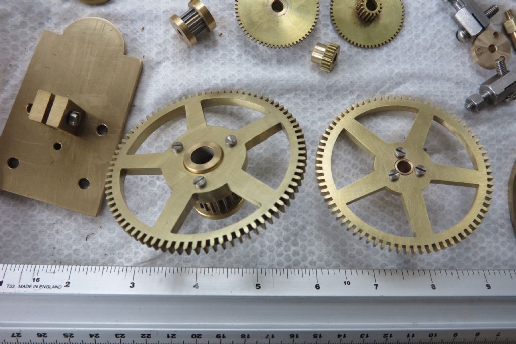
      I used the single button method with a twist , the button was a length of carbide mounted tangentially and 1 side of the blank machined then taken off the mandrel and reversed and the second side machined. This was for Wildings turret clock which works very well.125b7937-ed71-499a-a043-67c0154c87ba.jpeg

      Given that you say your method worked , why did you not traverse the crosslide and topslide to turn the second face?

      regards Martin

      Advert
      #567545
      John Haine
      Participant
        @johnhaine32865

        Because you only have to get one feed right.

        #567546
        John Haine
        Participant
          @johnhaine32865

          Actually this raises an interesting point. Since all the gears in a clock famously rotate only one way, it shouldn't be necessary to machine a symmetrical profile on each tooth. The other side could for example just be a buttress to give reasonable tooth strength. Then you need to assemble the gears the right way round to make sure the teeth mesh on their "right" sides.

          #567567
          ega
          Participant
            @ega

            I recently acquired a profile lathe tool with a 12mm diameter carbide insert – an instant single button tool, perhaps?

            #567583
            John Haine
            Participant
              @johnhaine32865

              Indeed, but quick calcs using Mike Cox's formulas says that for a 20 tooth 20* PA gear the mod would be 1.7542mm. You can choose 3 of button diameter, PA, teeth or mod, but not all at once alas.

              #567629
              bernard towers
              Participant
                @bernardtowers37738

                Martin, The reason being that you would need another tangential toolholder of the other hand. Plus the blank is butted up to the collet chuck nut so no room to get to tother side

                #567634
                John P
                Participant
                  @johnp77052

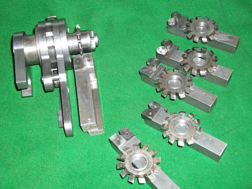
                  Button form tools used on the Eureka device can be a problem
                  to make in the sizes above cutter No 4 the radius is so large
                  that it would interfere with the body of the device , see here the photo
                  of 6 off 20 DP 20 pa cutters and tooling to make them .
                  Only a small part of the circle is needed to form the cutter in the
                  sizes 3 to 1.

                  eureka 1.jpg

                  These illustrations taken from an old book shows how this used
                  to be done and may be of some interest especially if you have
                  a shaper ,i don't need to add any more the pages show it all.

                  John

                  relieving1.jpg

                  relieving2.jpg

                  relieving3.jpg

                  #567928
                  Howard Lewis
                  Participant
                    @howardlewis46836

                    There was an article in M E dated 2nd September 1994 which dealt with gear cutting and in which there were some a table giving button sizes and spacing, which may be of help.

                    Howard

                  Viewing 8 posts - 26 through 33 (of 33 total)
                  • Please log in to reply to this topic. Registering is free and easy using the links on the menu at the top of this page.

                  Advert

                  Latest Replies

                  Viewing 25 topics - 1 through 25 (of 25 total)
                  Viewing 25 topics - 1 through 25 (of 25 total)

                  View full reply list.

                  Advert

                  Newsletter Sign-up