Some VERY interesting LED modules

Advert

Some VERY interesting LED modules

Home Forums Electronics in the Workshop Some VERY interesting LED modules

Viewing 25 posts - 101 through 125 (of 135 total)
  • Author
    Posts
  • #631230
    Robin Graham
    Participant
      @robingraham42208
      Posted by Michael Gilligan on 26/01/2023 21:58:17:

      Posted by Robin Graham on 26/01/2023 21:38:31:
      .

      On the LUXdrive units (they look nice!) I couldn't see a Vout on the site Michael linked to (may have missed something?) but the LUXdrive A011-D-V-700 is available in the UK from Digi-Key for £20.50 and they give a maximum Vout of 48V – so they should be fine for this application.

      […]

      .

      Links within Links will get you here: **LINK**

      http://www.leddynamics.com/wp-content/uploads/2018/12/A011_FlexBlock_v2.0.pdf

      What you seek is declared on the second page thereof.

      MichaelG.

      […]

      Ah, I did indeed miss something – an all too frequent happening these days. My intention was to give a source for compatible leddynamics drivers in the UK if anyone was interested.

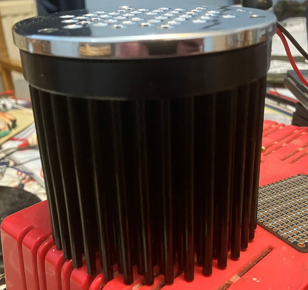
      I'm possibly alone in fretting about heatsinks, but in the spirit of publishing ones findings whatever I bought some round jobs from eBay:

      heatsinkmounted.jpeg


      Perhaps overkill as it runs at about 65 degrees at the centre of the array (without the dreaded thermal paste) but it'll do for my needs.

      Now I've got the arrays up and running (It's been journey into new territory for me! ) my mind turns back to Michael's original post – the point of these things is that they give a directed beam without ancillary optics. Which they do!

      Robin.


      Edited By Robin Graham on 29/01/2023 00:23:41

      Advert
      #631236
      Michael Gilligan
      Participant
        @michaelgilligan61133

        Posted by Robin Graham on 29/01/2023 00:18:49:

        […]

        Now I've got the arrays up and running (It's been journey into new territory for me! ) my mind turns back to Michael's original post – the point of these things is that they give a directed beam without ancillary optics. Which they do!

        Robin.

        .

        Thank you, Robin ^^^

        It really is a very clever bit of optical design and [in some situations] a massive improvement over the more common COB-LED units with their large area light source.

        MichaelG.

        #631255
        Robert Atkinson 2
        Participant
          @robertatkinson2
          Posted by Robin Graham on 26/01/2023 21:38:31:

          On the LUXdrive units (they look nice!) I couldn't see a Vout on the site Michael linked to (may have missed something?) but the LUXdrive A011-D-V-700 is available in the UK from Digi-Key for £20.50 and they give a maximum Vout of 48V – so they should be fine for this application.

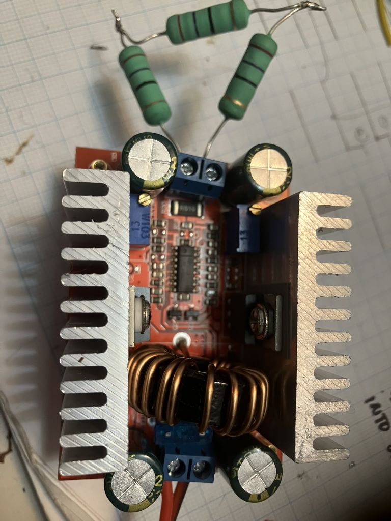
          On other (cheaper) solutions I, like Noel, ordered a 400W booster (£8.49):

          dc_booster.jpg

          Reading Les' account I went very carefully! With 10V input and no load I adjusted the output to 12.5V – the module drew ~10mA. Connecting an 81 ohm load (shown) the voltage remained stable and it drew 220mA at the input . Cranking the current pot right down the voltage across the load dropped to 11.5V, so I guess it's working as expected and I'm hopeful that it will be OK to drive the LED array..

          A slightly odd thing is that the +ve output appears on the leftmost heatsink in the photo. Something to be aware of if going down this road.

          Robin.

          The bit of Les' account you should pay attention to is " I would not advise anyone to buy one of these regulators to power the Plessey LED modules. "

          Your test is not conclusive. To ensure a constant current generator is working correctly you must change the load, not the output voltage or current.
          Assuming you don't have an ammeter, with your set up the test would be:

          Set the voltage control higher than required for the maximum current you want to flow
          Connect 3 resistors in series across the output
          Set the desired current (for the test load) or turn down until the output voltage just starts to drop
          Measure the voltage across the load. and not the value.
          Short out one resistor
          Measure the voltage across the load and ensure it changes to 2/3 the value for 3 resistors.

          Your resistors look like 100 Ohm to me, but photo and screen colours are dificult. Assuming they do total 81 (3 x 27) Ohms, at 12.5V maximum current would be 150mA so if current was set to less than this, say 120mA, the voltage will drop (to 9.7V for 120mA). Shorting out a resistor will, if it is a constant current supply, cause the voltage to drop to 2/3rds (6.5V for 120mA).
          Values will be +_ 10% typically.

          If it is not a constant current supply you will find it very hard to set the voltage with the load connected and the voltage will not drop when you short out one resistor.

          Robert G8RPI.


          Edited By Robert Atkinson 2 on 29/01/2023 11:32:11

          #632068
          Robin Graham
          Participant
            @robingraham42208

            Robert – apologies for not responding earlier, I have only just got back to this.

            I have now made experiments along the lines you suggested. My procedure and results:

            – set PSU to 12V in CV mode

            – adjust voltage pot on convertor to give 24.5V no load – PSU is indicating 10mA at this point.

            – attach load (definitely 3 x 27 ohm 5W resistors in series) and wind down current pot on convertor to give 24.0 V

            – attach voltmeter over the central resistor in load – 8.05V as expected. The PSU is supplying 660mA.

            – short out one of the other resistors, momentary flicker, but 8.03V across the central resistor.

            So that seems good – it's current limiting.

            However…

            Removing the short then turning the current limit from the PSU right down I find that:

            – if I turn it up again straight away (within a couple of seconds) the PSU voltage / current return to 12V / 660mA immediately and all is as before.

            – if I leave it for ~15 minutes with the PSU current down to zero, then turn it up to max (3A) the PSU supplies the full 3A. At this point the the voltage from the PSU is about 6.9V and the voltage across a single load resistor is about 7.5V. After approx 70 seconds in this condition the PSU suddenly switches back to 12V and 660mA and the convertor output jumps back to 8.05V per resistor.

            Does that give any clue as to what is going on with these modules? I haven't tried connecting to 12V lead acid battery (which was what I'd hoped to do) because I suspect that the convertor would suck up too much startup current and self-destruct, as Les found.

            Robin.


            Edited By Robin Graham on 04/02/2023 23:38:19

            Edited By Robin Graham on 05/02/2023 00:02:58

            Edited By Robin Graham on 05/02/2023 00:47:30

            #632295
            Michael Gilligan
            Participant
              @michaelgilligan61133

              Just a note:

              The non-dimmable power supplies are on offer again: **LINK**

              https://www.ebay.co.uk/itm/195351986113

              MichaelG.

              #632305
              Ian P
              Participant
                @ianp

                Thanks for the link Michael, I''ve just ordered two.

                Ian P

                #632504
                Michael Gilligan
                Participant
                  @michaelgilligan61133

                  Probably drifting a little off-topic, but I started the thread so what the heck devil

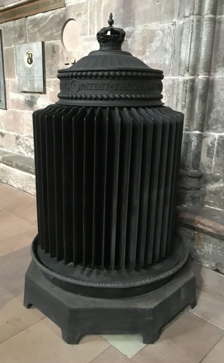
                  I visited Chester Cathedral today, and admired these Gurney Patent heaters:

                  .

                  3f5288db-01fd-4cde-a67a-195a26868d66.jpeg

                  .

                  Inspiration for a ‘heatsink’ perhaps.

                  .

                  Incidentally: They were decommissioned when trendy underfloor heating was installed

                  … with the result that the stacking wooden chairs in that area had to be scrapped, because they warped !!

                  MichaelG.

                  .

                  Ref. __  https://www.gracesguide.co.uk/Gurney%27s_Patent

                  Edited By Michael Gilligan on 07/02/2023 21:38:44

                  #632509
                  noel shelley
                  Participant
                    @noelshelley55608

                    A truly wonderful device ! Bolted to a semiconductor how many 100/ 1000s of As can be disipated ? I 'll be back ! Noel.

                    #632518
                    Michael Gilligan
                    Participant
                      @michaelgilligan61133

                      Footnote:

                      I have not yet found a downloadable copy of the patent for Gurney’s Stove, but one page is included here:

                      **LINK**

                      http://www.hevac-heritage.org/victorian_engineers/gurney/gurney.htm

                      [ not that it’s particularly relevant … it’s just admirable ]

                      MichaelG.

                      #770856
                      Ian P
                      Participant
                        @ianp

                        After Michael allerted us to these LED modules I purchased four of them (and four driver units) and after powering one up fastenned to an ali plate, quickly realised that the heatsink needed to be rather more substantial.

                        I am not sure what the original lighting fitting that these were intended to be used with but I suspect it probably incorporated a fan. For the use I had in mind for these modules I want them to be silent so since I’ve had them they have sat on the shelf.

                        Has anyone here put these modules to good use?

                        Ian P

                        #770861
                        Michael Gilligan
                        Participant
                          @michaelgilligan61133

                          Ian

                          Did you download the data-sheet [from RS] that I mentioned in the opening post ?

                          … for convenience:

                          https://docs.rs-online.com/3995/0900766b8161ece2.pdf


                          MichaelG.

                          #770864
                          SillyOldDuffer
                          Moderator
                            @sillyoldduffer
                            On Jim Butler 1 Said:

                            Posted by Michael Gilligan on 08/01/2023 22:59:35:

                            Posted by Robert Atkinson 2 on 08/01/2023 21:17:24:
                            Interesting that there is a bridge rectifier on the board.

                            .

                            … especially as the data-sheet appears to say it should not be reverse connected.

                            MichaelG.

                            Looking at the track pattern in the picture, the AC terminals of the bridge rectifier seem to be routed to the power input connector.

                            In which case, reversed polarity supply would not be a problem.

                            JimB

                            My guess is the bridge rectifier is a Mk2 improvement.

                            A foolish young engineer might have designed the Mk1 on the assumption that no customer would ever be stupid enough to reverse the power leads.  He believes customers will read and understand the instructions, won’t take silly shortcuts, and are never confused.

                            Several thousand burnt out returns later, he realises the awful truth – that on a bad day everyone is an idiot –  and protects the Mk2 with a bridge rectifier.   Why not install a rectifier in the Mk1 on day one?  A rectifier reduces efficiency and bumps the price up.  Both small savings but worth having provided the unit is wired correctly.  I suspect many aren’t wired correctly, and note the difficulty newcomers may have identifying a suitable power supply.

                            🙂

                            Dave

                            #770866
                            Michael Gilligan
                            Participant
                              @michaelgilligan61133

                              IMG_0410

                              #770868
                              Robert Atkinson 2
                              Participant
                                @robertatkinson2

                                I used one for a stroboscope with good results. It was a one-off application so I just lashed up a circuit.

                                Due to low duty cycle minimal heatsinking was required.

                                Robert.

                                #770871
                                Ian P
                                Participant
                                  @ianp

                                  I did download and read the datasheet at the time, I just looked again now and whlst it has much info on the optics there is sparse reference to its heatsink requirement. There is a picture showing this (5.6mm thick) module alongside a standard COB which is 175mm high, I agree this is quite an impressive reduction in size for an equivalent optical performance.

                                  However regarding heatsinking (the datasheet does say:

                                  By adding a driver and a lightweight heat sink consumers can experience a new quality of directional light.

                                  So a lightweight heatsink (but I suspect one that will not be inexpensive)

                                  Ian P


                                  #770877
                                  Michael Gilligan
                                  Participant
                                    @michaelgilligan61133

                                    From a source picked almost at random … here is a fairly representative commercial 1°C per Watt passive heatsink:

                                    https://www.mouser.co.uk/datasheet/2/657/ourproducts_hsseries_heat_sinks_hs103_datasheet-2933908.pdf

                                    Doing it on the cheap is clearly the preferred alternative, but that should give you a sense of what’s needed.

                                    MichaelG.

                                    #770891
                                    Ian P
                                    Participant
                                      @ianp

                                      Michael, (not because you linked to it) but that is not what I would describe as ‘lightweight’ especially in relationship to the module and the Plessey datasheet size comparison that sort of infers it is a far more compact total package than the standard ‘COB’.

                                      The Plessey datasheet states that the module itself has a 1°C per Watt thermal resistance, I’m not sure how to interpret that.

                                      Ian P

                                      PS, I resurrected the thread purely because I wondered how other forum members had deployed their modules.

                                      #770926
                                      Michael Gilligan
                                      Participant
                                        @michaelgilligan61133

                                        Sorry, Ian, I can’t really help

                                        My understanding [meagre as it is] was that when running at full power, each module would require a 1°C per Watt heat-sink for it to remain cool.

                                        I have only run mine for a few seconds at full power, and like Robert, am intending to use them in a flash unit [for photomicrography in my case] … the tiny mark/space ratio should mean that I only need modest heat-sinking.

                                        Other matters have conspired to put that project on Hold.

                                        MichaelG.

                                        #770976
                                        Les Jones 1
                                        Participant
                                          @lesjones1

                                          I think the 1 degree C per watt is the themal resistnace between the metal back  surface and the device junctions.  The data sheet probably also gives the maximum recomended junction temperature. So with the 1deg c/W theramal resistance of the device if it is consuming 30 watts the junction temperature will be 30 deg, C hotter than the metal mounting surface.

                                          Les.

                                          #771012
                                          Robert Atkinson 2
                                          Participant
                                            @robertatkinson2

                                            Les is correct.

                                            The datasheet thermal resistance is Junction to case, Rthj-Tc. Actually specifed in Kelvin per Watt but that’s the same as C/W.
                                            You have to subtract that from the calculated heatsink thermal resistance for a given LED and ambient temperature.

                                            Robert.

                                            #771016
                                            Michael Gilligan
                                            Participant
                                              @michaelgilligan61133

                                              Les & Robert

                                              Many thanks for the input … ’though I confess to being confused by what exactly it would mean in a ‘real-world’ implementation.

                                              Just for convenience, let’s suppose I wanted to run one of those modules continuously, flat-out, in a domestic environment at an ambient 20°C … how would I specify a suitable passive heat-sink ?

                                              Thanks in advance

                                              MichaelG.

                                              #771095
                                              Robert Atkinson 2
                                              Participant
                                                @robertatkinson2

                                                So the electrical specification is Forward Voltage 44V and maximum continuous current 700mA (0.7A). Thus the power input is 44 x 0.7 = 30.8 W. Taking a conservative 30% efficiency gives 21.6W of heat. The absolute maximum temperature of the case (mounting surface) is 90 degrees C.  For you specified ambient of 20 degrees this is a maximum rise of 70 degrees. The temperature rise of a heatsink is the power times the thermal resistance of the heatsink delta T = P x Rth. We can rearrange to find the required Rth = delta T / P. So for 21.6 W and 70 deg  we get  3.2 degrees C/W as a minimum size heatsink.
                                                We don’t consider the 1 degree C/W o the datasheet because the we have used the specified maximum case temperature not the LED chip temperature. The chip temperature will be 1×21.6 higher or 111.6 degrees C.
                                                Note that 20 degrees is a pretty low ambient. If we take 30 you need a 2.8 degree C/W heatsink.

                                                A 150 x 150 x 1.5 mm aluminium sheet is about 3.3 degrees C/W thermal resistance. 200 x 200 x 1 mm is about 3.1 C/W. Better if anodised or thinly painted black. There are calculators online for simple heatsinks.

                                                Robert.

                                                #771102
                                                Michael Gilligan
                                                Participant
                                                  @michaelgilligan61133

                                                  Many thanks for that run-through, Robert

                                                  Hopefully it will bring some comfort to IanP

                                                  MichaelG.

                                                  #771375
                                                  Ian P
                                                  Participant
                                                    @ianp

                                                    Michaels question (in 771016) about heatsink requirement for continuous domestic use was exactly what I was going to ask when otehr matters kep me away from the forum.

                                                    Robers reply has me a bit confused (normal for me!) regarding the power consumed and the 30% efficiency. Does that mean that if the LED was replaced by a resistor drawing the same current and consuming the same amount of power (the 31.8W) the heatsink requirement would be different?

                                                    In my mind, if (whatever) power consuming device is in put in box box the PSU does not know what it is driving but the box still has to dissipate the 30 Watts. If the LED was 100% efficient and no light escaped the box the power woudl still be the same?

                                                    I did some testing a while ago with the LED module fixed to one face of a 15cm ali cube, 4mm wall but various holes & cut-outs, after 30 minutes running it was about 50 or 60c (photo to follow).

                                                    Ian P

                                                    #771405
                                                    noel shelley
                                                    Participant
                                                      @noelshelley55608

                                                      Robin Shows a pin fin heat sink of 75mm dia and about 150 pins of 60mm long with a 10mm thick base which I had deemed ample. One thought is to use the heatsink membrane between the LED unit and heatsink. It was about £8. If this was not enough I would mount a small 12v computer fan on the back of the pins to stir the air. The whole affair would be very compact as I intend to mount the PSU on plastic stand offs from the pins. It all still sits on the mantle shelf but this has prompted me to look at the idea again. Noel.

                                                    Viewing 25 posts - 101 through 125 (of 135 total)
                                                    • Please log in to reply to this topic. Registering is free and easy using the links on the menu at the top of this page.

                                                    Advert

                                                    Latest Replies

                                                    Viewing 25 topics - 1 through 25 (of 25 total)
                                                    Viewing 25 topics - 1 through 25 (of 25 total)

                                                    View full reply list.

                                                    Advert

                                                    Newsletter Sign-up