I have Solid Edge community edition 2021 installed on my Windows11 computer with plenty of system ram and a good graphics card also with plenty of ram. I am more used to Design Spark mechanical 5 and FreeCAD 0.19, but I wanted to get into SE because it has a lot more features. Three things bugged me about SE.
1) the feature tree is just one one list of everything you've done. In DS5 and FC, each body has its own list that can be collapsed down to just the title of the body.
2) The colour for active parts and inactive parts seem to be the same. The transparency of inactive parts can be altered, but not the colour, even though in the settings menu different colours for the active/inactive can be set, it has no effect.
3) When I want to draw on a surface that is obscured by other bodies both FC and DS5 will crop or section the body at the drawing plane. I couldn't find a way of getting SE to do this. It makes drawing easier if you can actually see the surface you are drawing on.
Before I download the latest version of SE could anyone tell me if the items above have been resolved? Or is it just me?
I have also used Solid Works student edition which worked like DS5 and FC, so it could just be me!
Not quite sure what you mean Lee, and I use FreeCAD a fair bit. Can you post some screen shots please?
I haven't had problems with SE2023; it's comes over to me as a slicker version of SE2022, without major changes.
Is what SE calls the 'PathFinder' what you mean by the feature tree?
In synchronous mode, it's not as important as the FreeCAD equivalent, so I don't use it much. Similar rather than identical, and in some ways I prefer FreeCAD's approach, but it's not a showstopper. The leff-side arrow symbols open and close levels.
On my machine, the active part is fairly clear, it's solid and everything else is transparent:
CTRL-Q toggles the visibility of the inactive parts, so they can be hidden whilst the active part is edited. If the colour is the same, I suspect the graphics card.
From the Solid Edge Options menu try changing the Application color scheme. Or experiment with the Graphics card settings top right of the Options->View screen.
I tried ctrl-q with no effect. I have 7 design bodies with one of them active. When I try to draw on a surface of the active body (ordered mode) the body rotates to present the surface face on, and the rest of the bodies cover the surface.
The description for ctrl-q in the customise screen is "hide previous level. I'm not sure what that means.
We may be using SE differently. I have one part per file and bring them together asassemblies, avoiding two or more parts in the same file. My comments and ctrl-q refer to parts being edited from within an assembly. Various advantages to this approach, one of which is parts can always be hidden.
I played with the multi-body feature as a way of splitting parts, but it's a mode I'm not comfortable with. My reluctance to use multi-bodies may be 'just me' (as you say!), but I found them quite confusing.
I've never explored assemblies. It sounds interesting, but I don't think it will answer the biggest problem I have with SE, being able to draw on a surface that is "hidden". I will get a screen shot of a part in Design Spark 5 to explain better.
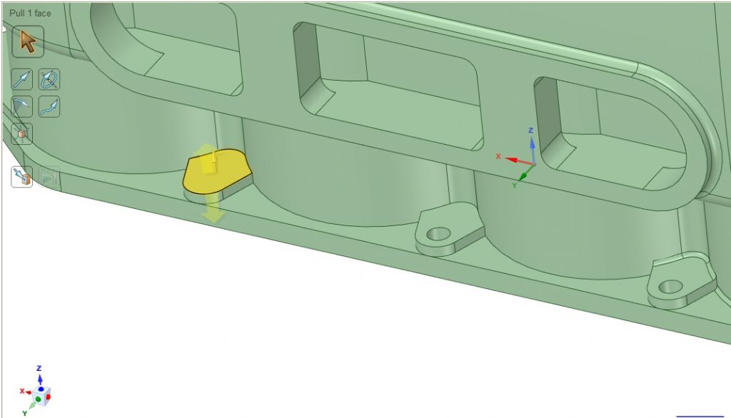
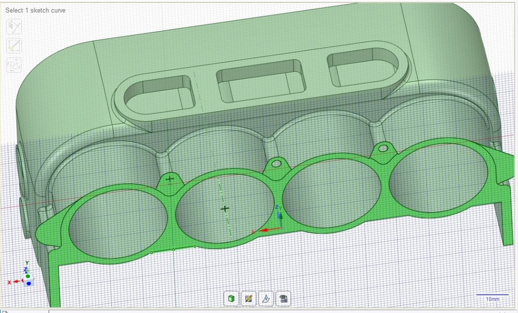
This image shows a surface in Design Spark 5 that I want to sketch on. The surface is highlighted.
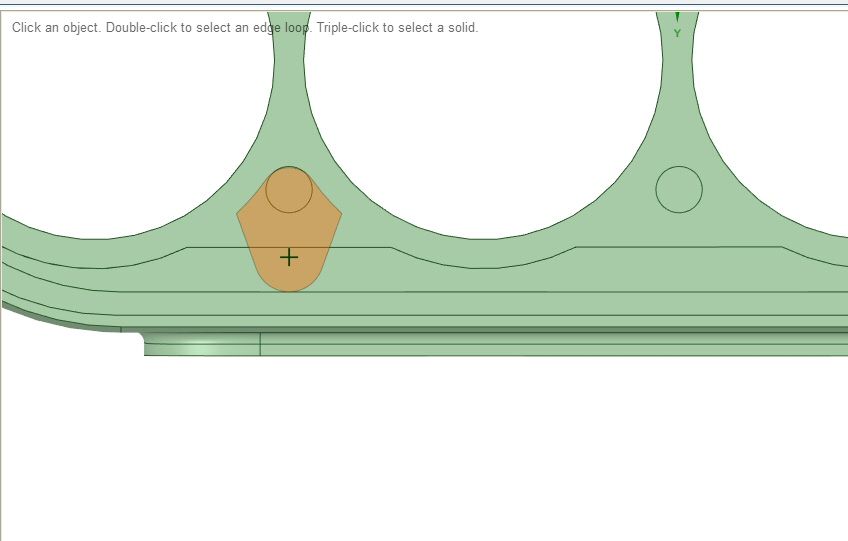
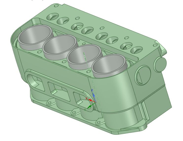
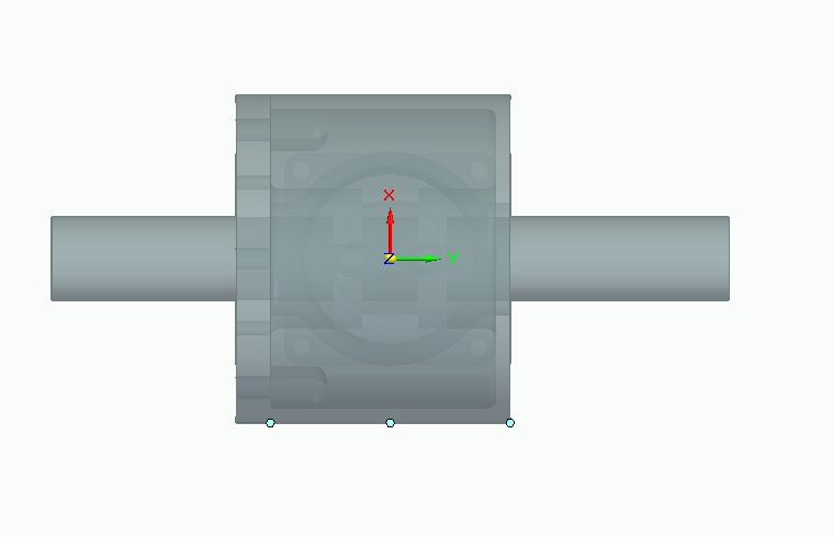
This image shows the surface visible from the top of the cylinder block, no other detail visible.
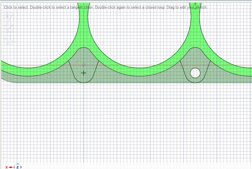
I start a sketch on the surface and the block is automatically "clipped" so that everything is visible.
I can rotate the part so that I can see the other side of the drawing plane and copy reference points from it.
I have drawn the stud hole and cut it out. The block is the active body, green, and the cylinder liners are inactive, grey.
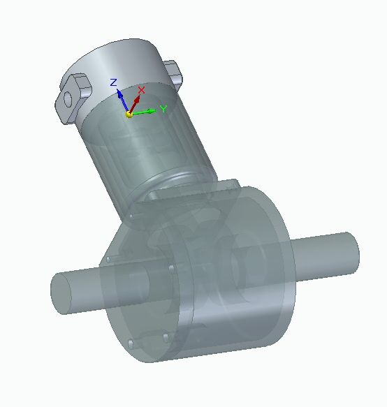
I do the same in Solid Edge to a simple engine, but can't see the surface to sketch on without hiding other parts. If I had drawn the same block in SE, It would have been very hard to draw the stud hole.
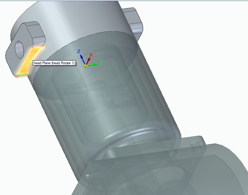
I select a surface to sketch on.
I can't see the surface.
Is there any way of automatically clipping the part at the sketch plane? I know I can add clip views, but that could get very messy.
Sectioning or making the part transparent would do it but a bit of a faff, Alibre allows you to "see through" anything above the surface or plane being sketched on much like your design spark example. F360 would seem to have the same problem as SE though I don't use that enough to know if there is a way around it.
Posted by Nicholas Wheeler 1 on 30/12/2022 09:54:35:
In F360, you hold the left mouse button down, and it gives a list of all the selectable edges, profiles, faces etc for you to pick.
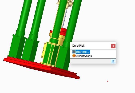
SE is similar, but I agree it's less obvious. The software has a number of ways of selecting faces. For example, this engine, a recreation of one of Jason's, is an Assembly. In this view the part I want to work on, the cylinder, is hidden behind a pillar:
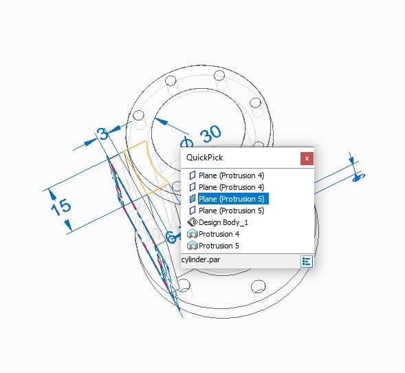
If I hover the mouse over the area, after a brief pause, the Quickpick menu appears. It lists all the features under the mouse and any of them can be selected. Of the two above, I click on the cylinder, but the pillar is still in the way:
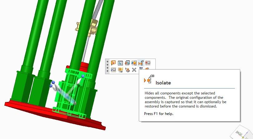
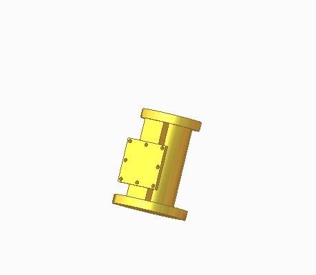
However, another menu opens with a bunch of buttons, one of which is 'isolate'. Pressing it hides everything bit the wanted part:
As can be seen the valve plate is unfinished, but so also are some internal details inside the cylinder. I can reveal more by switching into line view. This also allows quickpick, so I can select a face inside the cylinder. It's the one outlined below in yellow, 'Plane (Protrusion 5), which I can draw on:
When drawing, the upper part of the cylinder is still visible in line view, but it can hidden with the Show and Hide commands.
Bit clunky I feel, but it can be done. A bit of problem with SE is exactly how stuff works might depend on which menu is active. I found SE harder to learn than Fusion and FreeCAD but it's OK now I'm used to it. Comparing CAD packages can be tricky, swings and roundabouts. For example, even though I consider Fusion better organised than SE, SE's synchronmous mode gives it an edge in many circumstances. But having synchronous and ordered modes makes learning SE more complicated.
I think Solid Edge isn't the programme for me. I have tried to get used to its way of working, but I'm comfortable with Design Spark 5. If DS5 could mirror a part and had good text capabilities it would be perfect!
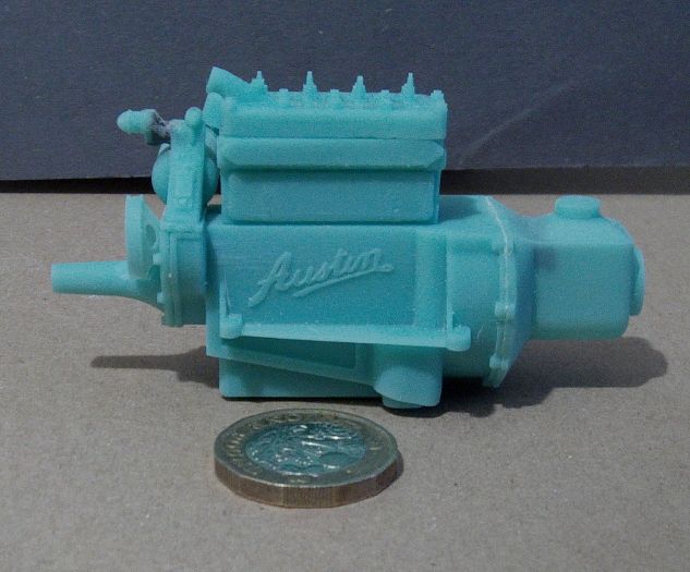
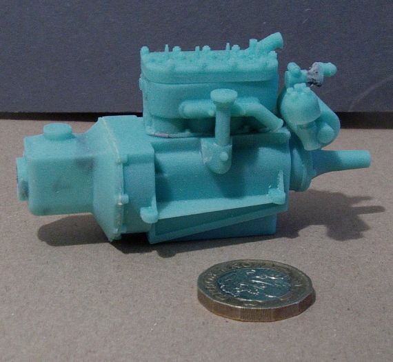
I took a break from trying to cast metal and started to design a one tenth scale model of my Austin Seven car in DS5. This is the 1/10th engine 3D printed in resin. I wont be using the engine in the model as I have decided on a closed bonnet model to simplify things. One pound coin for scale. The 3D print is made up of 8 pieces.
The block and head are printed separately and aren't glued on until they are painted.
Click on options, view, dynamic clipping and turn it on.
I set mine to LT gray and 100% opacity. Click on OK to accept the settings.
To set a clipping plane go to view on the menu bar, click on set planes, click on the surface to set the plane on, in my case it's a surface hidden from view by an overhang above it. I am a bit baffled by the next bit -offset- I just set it a short distance from the surface and chose which side for the plane and clicked on finish. The part is now clipped ready to sketch on.
Once I had a sketch created I clicked on the green tick which brought back the full menu bar to click on view and turn off set planes so I could work with the full body again before ending the sketch.
I feel that SE has made what should be a simple process, complicated and I had hoped the newer versions had been improved.
I have also used SolidWorks, FreeCAD and DesignSpark Mechanical 5, they all have a much better clipping process, in DSM5s case, it is automatic when you select a surface to sketch on, it is clipped.
Have you tried asking on the Solid Edge online community?
Can't help feeling you have grabbed hold of the wrong end of the stick here and are trying to drive Solid Edge in a way its not really intended to be used. Your work around looks like the sort of feature / process that is there to be used when you aren't really in the "right place" for things to come out the natural way the program likes but just need to make a quick tweak. Circling back to the right place and returning being more trouble than a slightly convoluted process.
For example it took me about 10 years to twig that VectorWorks had a easy way to do something that I'd found a marginally convoluted way to do whilst trying to drive it like MacDraw! Having twigged that it opened up a fair number of esy ways to do things that I'd previously never really understood. I use VectorWorks as a simple 2D drawing board substitute so way less complicated than SE.
A hunt round the internet will turn up several free sources of book downloads on Solid Edge. Makes it easy to test drive them before buying the one that works for you. Whatever your views on piracy there is no way I'm spending £50 or more on a manual without being sure it will help me. Download or internet tutorials are no subsitute for a book, even if you have two computers or computer & tablet.
I may be a bit perverse in my way of thinking, but I shouldn't have to ask the users of SE how to draw on a surface that is obscured, it should be obvious. I liken it to drawing on a piece of paper when there are one or more sheets of paper stacked on top. As I stated above, all three of the cad programmes I have used have a simple, obvious process of actually seeing the surface you are drawing on. I can't find any way of doing it in SE, and so far, nobody has told me they have found a way. If FreeCAD can do it, so can SE.
I haven't looked for a book on SE, thanks for the suggestion. I am also with you on piracy, I still have the installation dvd for SolidWorks for which there are websites offering a hack to get the full version from the disc, free. I would rather buy a cut down version of SolidWorks with a lifetime license than use SE, but SE is free. I will continue to use SE and hope I can put up with its quirks!
I wonder why there is such a thing as a clipping plane if its not for what I am using it for? It is a messy way of doing what I am doing, but what other use has it got I wonder?
Entirely agree that for a modern 3D CAD program it should be entirely obvious how to draw on a surface that is obscured. Or, more correctly I suppose, obvious how to bring said surface forward so you can draw on it.
The fact that it isn't immediately suggests that you have either missed something "obvious when its explained" or are using your familiarity with another program to find a "wrong way" that can be made to work. Been there, dunnit, got the Tee shirt in other situations and wondered how I could ever have missed something so simple.
On-line communities are usually good in such situations as there is almost always some one else who has been in the same situation.
I long ago concluded there is nothing simple about 3D CAD!
Away from home right now so I don't recall which Solid Edge book I bought after evaluating 3 or 4 downloads but even with a book my learn Solid Edge in 2022 resolution stalled out due to not being able to allocate enough time. In retrospect the Audel one may have been a better buy than the one I plumped for, as I recall the choice was either a coin toss or faster delivery.
This SE tutorial has been suggested/recommended elsewhere and I've certainly learned some new approaches from it. Very often it's not enough just knowing what tools are available but how best to apply them – and (at least to me) that has not always been so obvious. It's quite long but worth working through in stages…might be too basic for more advanced users but for folk like me (e.g. still reading "CAD for Dummies" it gives some useful 'best practices'
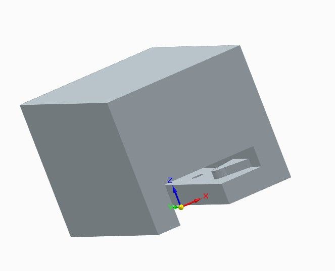
I'm grateful to Ian for identifying a Solid Edge problem I didn't know I had! I think it's because I've never drawn an object like Ian's engine in that way, but it's a valid way to do business.
Although SE can select and work on hidden surfaces, it doesn't automatically hide what's in the way. Unless someone knows better, it seems you have to set up clipping panes (a 3-step process in the View menu), and show the slice, which can be worked on in the usual way.
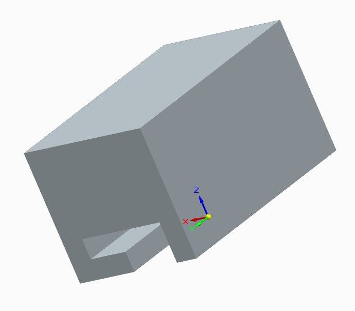
I created this slotted box, so I could work on the inside:
Setting planes allow this temporary view, temporarily hiding whatever is above. I drilled a hole and extruded the raised platform:
Turning the clip off reveals the whole item, with the new features on the shelf:
Be nice to have a single button that rendered everything above a plane invisible. I suspect the 'set planes clip' method is more general purpose than that and does other useful things as well. Needs to be explored further.
Thanks for the link to the video, I have watched nearly an hour and have learnt a lot. He makes synchronus look easy!
Lee
Synchronous is SE's best feature – once you get used to it! FreeCAD, Fusion and most of the others all build models from a series of related steps, thus changing an existing feature requires backtracking through history, and hoping the change doesn't upset anything done later. However, recorded history, which SE calls 'Ordered' works well and is logical. In this way of working the 'Feature Tree' is important.
SE's "synchronous mode" allows many changes to be made without backtracking. Doing so makes the history much less relevant, and the 'Feature Tree' becomes far less important. In fact trying to use it in the same way as Fusion is likely to derail Solid Edge unless it's in ordered mode. Synchronous is confusing and alien until you get used to it, then it suddenly becomes wonderful.
I think 'confusing and alien' is a common first reaction to all 3D-CAD packages. They're like learning to ride a bicycle. Much falling off and many discouraging failures until suddenly the mind clicks, then it makes sense, and away you go.
Expecting software to work in the same way as previous experience suggests it ought to can be a serious obstacle. When I was a lad up to 50% of experienced 2D drawing board draughtsmen couldn't cope with 2D-CAD. A few years later about 30% of 2D-CAD trained draughtsmen couldn't transition to 3D-CAD. Nothing to do with intelligence. More to do with the difficulty of breaking a habit. The mind has to accept a different approach is essential, and it often prefers not too! We all suffer but some minds would rather die in a ditch than adapt.
Design Spark works in much the same way as synchronus. Once you have used a sketch to create a solid, the sketch is gone and can't be edited unless you undo the solid stage back to the creation of the sketch. I hope that makes sense. The solid can be altered on the fly, extruding or adding draft to a surface etc. A new sketch can be started on any planar surface or on a plane to add extra features. If you creat a hole in a solid the hole can be moved or its diameter changed easily. All of the ways of working I am used to in DS exist in SE, but SE has features that the free version of DS doesn't have. I.E, mirroring a part and the creation of a drawing. And SE also has the ability to produce animations, that might or might not be handy, but it is a long way down the road.
To teach myself SE I am creating a part in ordered mode, then starting a new file and creating the same part in synchronus mode. The steering wheel is taking some getting used to, but I have to admit things would be easier help wise if my cad computer was connected to the internet.
I have been experimenting with SE for a short while, trying to get the colours of active and inactive parts to be different with no luck. I can have the inactive parts semi transparent, but that's not a look I like. Somehow I have now changed the colour of my menu bar and can't get it back to default, any ideas? It's not urgent or important, I would just like to know how to do it.
I may not be understanding exactly what you are doing Lee – but you can restore a "Used" sketch after you've extruded a part. This is covered in the video I think…
You can use F360 in a similar way by turning off the timeline. But this does make creating robust, easily understood models more difficult. That's not particularly important with a simple part, but when working with a complicated assembly being able to track the development is far more important to me.
In MoI you can highlight any number of faces, curves or edges and have everything else disappear by 'right-clicking' on the Hide icon. Thus leaving only the highlighted items available for editing etc. Maybe Solid Edge has something similar?