Gary –
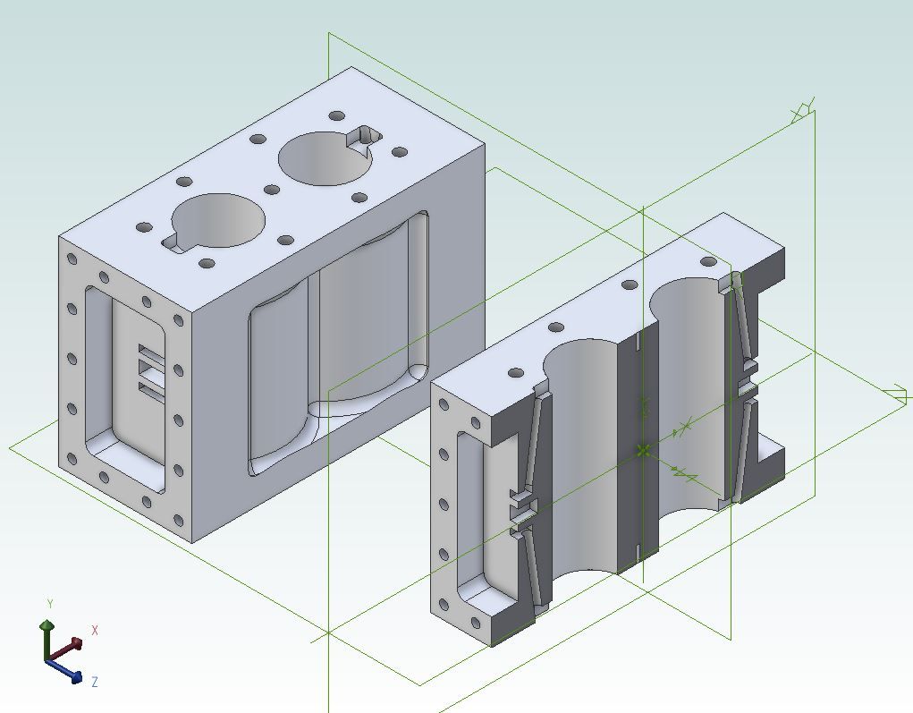
I tried to copy as a jpg image what I'd drawn but it loses the rendering, leaving a confusing wire-frame. However –
– Thank you Jason.
Yes – nearly as I have it although I am making the valve-chests as separate parts, not integral as you have them. Also the two side-recesses I have drew are simply flat-bottomed, not profiled.
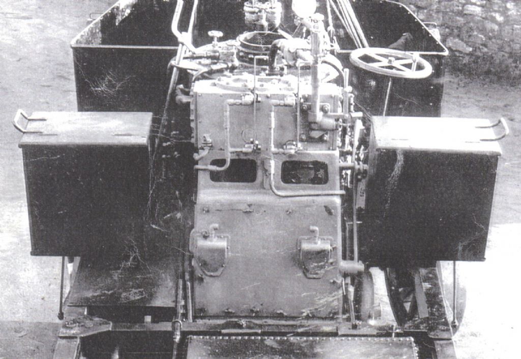
I have provided my covers with 6 studs, with the steam passages as two drillings on each side of the outermost studs (rather as on Luker's 'Ballarat' . It is not easy to tell on the photo the prototype cover fastenings.
The only significant difference between your 3D image and mine is the valve-chests.
'
Now, what CAD package do you use? It's clearly not TurboCAD 19 Deluxe. The green rectangles are very different from TC's 'Work Planes". TC uses only one work-plane at a time, visible on request, but its system of co-ordinates, WP and view-direction menus allow building onto any selected facet of the drawn object. Only, it is a very confusing, baffling system.
The default WP, called "World", is the imaginary floor for Extruding 2D upwards to form the 3D image. Extending an extrusion beyond the end surfaces, then Subtracting it, is the only way to show a hole in an 3D object.
====
Nicholas –
Your illustration is nearly as I have reached so far, although lying on its side. And with 6 studs, because that's a nice thing to draw! (And probably original, though hard to know for sure.)
Mine is fully extruded from a construction of rectangle and circles – the only practical method in TurboCAD.
(The alternative way, assembly from library solids, is harder. It may fail too, because TC uses at least 3 internal ways to generate 3D figures; with correspondingly different, often unexpected, results.)
'
… and David Jupp–
"Box" is TC's term for an editable cuboid from its solids library. To form the side recesses and ports, the available method is to sink a "Box" into the surface, then Subtract it from the surroundings.
It worked for the recesses but I was unable to repeat the exercise for the 6 ports.
'
I must admit I had not thought to use Mirror. I have just tried it – it does work in 3D. Nor to use Radial Copy for the studs, probably because I was preoccupied with them not breaking into the passages.
That is why I am trying to re-design the block: I started making it years ago, from some basic drawings, and it is accumulating all sorts of physical problems I did not foresee!
The methods I use in TurboCAD work, but are slow, clumsy and not as TurboCAD intends.
===
A note on terms and concepts:
TurboCAD (or at any rate 19 Deluxe) does not have "Constraints", "Sketch" or "Symmetric".
It does let you connect entities, symmetrically or otherwise, very efficiently and accurately, using the "Reference Point" embedded in any library or drawn entity; but I have never been able to make that work.
Instead I have to use its simple "Assemble" by, say, vertices; then calculated cross- moves.
Boolean Adding and Subtracting are fundamental in TC for combining inter-leaved entities into single ones. Eg, rectangles into the sections for angle- and channel- material.
TurboCAD is meant to be driven without doing its sums for it!
===
Re. live discussion: Sorry, but I do not have the equipment. (I have just sent an apology for absence from a forthcoming AGM to be held in Zoom.)
One member here has kindly offered me a memory-card to try in my PC. The computer, only 8 years old, will already take WIN-10 but if the RAM extension works, installing both will extend the computer's useful life and let me try SolidEdge; without needing a completely new system.
Nigel Graham 2.


 . It is not easy to tell on the photo the prototype cover fastenings.


