Have just abandoned another attempt at 3D drawing in TurboCAD.
Are other packages simpler?
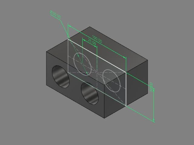
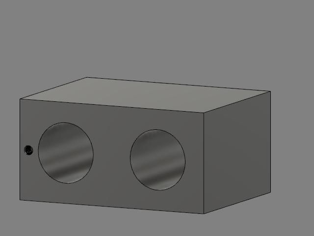
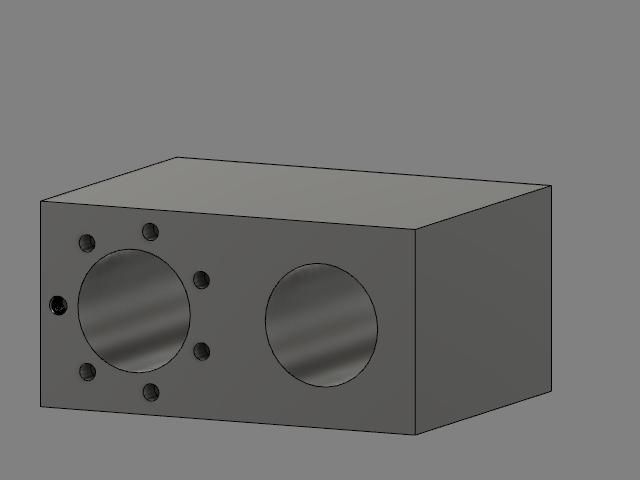
The cylinder-block for my waggon's vertical compound engine, copying from the 2D elevations. I also converted it to close round-number mm dimensions for simpler drawing.
1) The bounding rectangle (the whole thing is a cuboid of stock cast-iron bar).
2) Circles for the cylinders, with small ones round them for the cover stud-holes (5 alone for each, plus central shared one),.
3) Extrude all 14, making the "holes" slightly over-height. Stick a little sphere to the block's front lowest corner as a landmark when twiddling the thing from view to view.
4) Work out the height move and laboriously copy all 11 stud holes to the top surface, protruding fractionally. (Ignore symbolising the threads.) Drop the lower holes and over-length cylinders similarly. The protrusions allow the the next stage…
5 …. Subtract all 24 "holes" to make holes. If left flush they tend to stay hidden under the surface.
Now then…. That's a big lump of cast iron, so rectangular recesses in the sides to lighten it a bit. Leave the corner radii to the slot-drill, and anyway the recess starts life on the drawing as…
6 … a "Box" library figure, so naturally has sharp corners.
7. Assemble the box-to-be-recess to the block by top edge-to-edge mid-points. It's now face-to-face, centrally by length.
8 Centralise it vertically by sliding it down by [ (block height – recess height) / 2 ].
9. Slide the box into the block by the appropriate axis-move, leaving a tiny protrusion.
10. Subtract box from block to create the recess.
11. Turn the lot round and repeat Steps 6 – 10.
Fine so far. The basic rendering even makes it look like a part-made cylinder block. Next the ports.
11. These need something like the above, complicated by being a "thick" box flanked by two thin ones to be placed on their respective port-faces, centralising across, setting to heights, sinking in and subtracting. More sums.
I had to abandon it with the 6 boxes floating vaguely in or around the block, but I could not move them to their correct places.
I realised that even if I solved that, I have no idea at all how to draw inclined passages in a 3D model, but I want the design to suit the real engine not a CAD exercise. Four 4 drilled ones per port, in pairs flanking the cover stud. (I think I found that configuration in one of Luker's designs.)
The PC still needs up-dating to WIN-10, but if other CAD packages are as difficult in 3D I may as well keep my TC 19 Deluxe and use only its orthographic mode.
Nigel Graham 2.


